CHRYSLER VOYAGER 1996 Service Manual
Manufacturer: CHRYSLER, Model Year: 1996, Model line: VOYAGER, Model: CHRYSLER VOYAGER 1996Pages: 1938, PDF Size: 55.84 MB
Page 161 of 1938
REAR DRUM BRAKE SHOE ADJUSTMENT
NOTE: Normally, self adjusting drum brakes will
not require manual brake shoe adjustment.
Although in the event of a brake reline it is advis-
able to make the initial adjustment manually to
speed up the adjusting time.
(1) Raise the vehicle so that the rear wheels are
free to turn. See Hoisting Recommendations in the
Lubrication And Maintenance Section, at the front of
this service manual.
Remove the park brake cable, for the wheel of the
vehicle that is being worked on, from the park brake
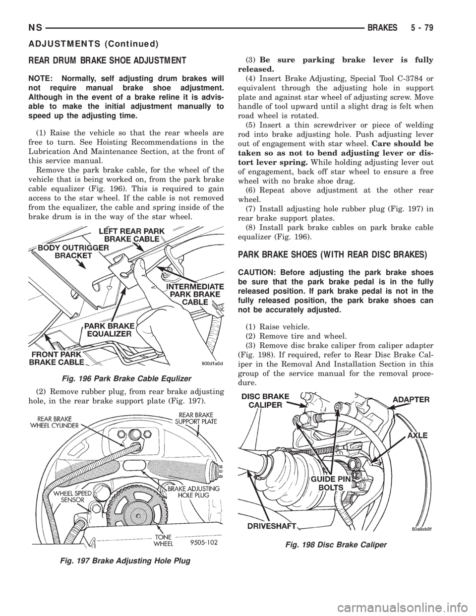
cable equalizer (Fig. 196). This is required to gain
access to the star wheel. If the cable is not removed
from the equalizer, the cable and spring inside of the
brake drum is in the way of the star wheel.
(2) Remove rubber plug, from rear brake adjusting
hole, in the rear brake support plate (Fig. 197).(3)Be sure parking brake lever is fully
released.
(4) Insert Brake Adjusting, Special Tool C-3784 or
equivalent through the adjusting hole in support
plate and against star wheel of adjusting screw. Move
handle of tool upward until a slight drag is felt when
road wheel is rotated.
(5) Insert a thin screwdriver or piece of welding
rod into brake adjusting hole. Push adjusting lever
out of engagement with star wheel.Care should be
taken so as not to bend adjusting lever or dis-
tort lever spring.While holding adjusting lever out
of engagement, back off star wheel to ensure a free
wheel with no brake shoe drag.
(6) Repeat above adjustment at the other rear
wheel.
(7) Install adjusting hole rubber plug (Fig. 197) in
rear brake support plates.
(8) Install park brake cables on park brake cable
equalizer (Fig. 196).
PARK BRAKE SHOES (WITH REAR DISC BRAKES)
CAUTION: Before adjusting the park brake shoes
be sure that the park brake pedal is in the fully
released position. If park brake pedal is not in the
fully released position, the park brake shoes can
not be accurately adjusted.
(1) Raise vehicle.
(2) Remove tire and wheel.
(3) Remove disc brake caliper from caliper adapter
(Fig. 198). If required, refer to Rear Disc Brake Cal-
iper in the Removal And Installation Section in this
group of the service manual for the removal proce-
dure.
Fig. 196 Park Brake Cable Equlizer
Fig. 197 Brake Adjusting Hole Plug
Fig. 198 Disc Brake Caliper
NSBRAKES 5 - 79
ADJUSTMENTS (Continued)
Page 162 of 1938
(4) Remove rotor from hub/bearing.
NOTE: When measuring the brake drum diameter,
the diameter should be measured in the center of
the area in which the park brake shoes contact the
surface of the brake drum.
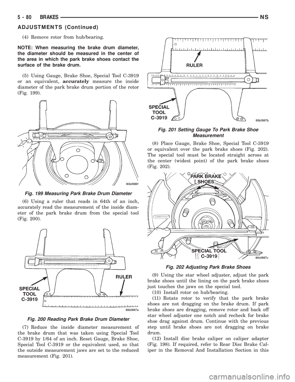
(5) Using Gauge, Brake Shoe, Special Tool C-3919
or an equivalent,accuratelymeasure the inside
diameter of the park brake drum portion of the rotor
(Fig. 199).
(6) Using a ruler that reads in 64th of an inch,
accurately read the measurement of the inside diam-
eter of the park brake drum from the special tool
(Fig. 200).
(7) Reduce the inside diameter measurement of
the brake drum that was taken using Special Tool
C-3919 by 1/64 of an inch. Reset Gauge, Brake Shoe,
Special Tool C-3919 or the equivalent used, so that
the outside measurement jaws are set to the reduced
measurement (Fig. 201).(8) Place Gauge, Brake Shoe, Special Tool C-3919
or equivalent over the park brake shoes (Fig. 202).
The special tool must be located straight across at
the center (widest point) of the park brake shoes
(Fig. 202).
(9) Using the star wheel adjuster, adjust the park
brake shoes until the lining on the park brake shoes
just touches the jaws on the special tool.
(10) Install rotor on hub/bearing.
(11) Rotate rotor to verify that the park brake
shoes are not dragging on the brake drum. If park
brake shoes are dragging, remove rotor and back off
star wheel adjuster one notch and recheck for brake
shoe drag against drum. Continue with the previous
step until brake shoes are not dragging on brake
drum.
(12) Install disc brake caliper on caliper adapter
(Fig. 198). If required, refer to Rear Disc Brake Cal-
iper in the Removal And Installation Section in this
Fig. 199 Measuring Park Brake Drum Diameter
Fig. 200 Reading Park Brake Drum Diameter
Fig. 201 Setting Gauge To Park Brake Shoe
Measurement
Fig. 202 Adjusting Park Brake Shoes
5 - 80 BRAKESNS
ADJUSTMENTS (Continued)
Page 163 of 1938
group of the service manual for the installation pro-
cedure.
(13) Install wheel and tire.
(14) Tighten the wheel mounting nuts in the
proper sequence until all nuts are torqued to half the
specified torque. Then repeat the tightening sequence
to the full specified torque of 129 N´m (95 ft. lbs.).
(15) Lower vehicle.
(16) Apply and release the park brake pedal one
time. This will seat and correctly adjust the park
brake cables.
CAUTION: Before moving vehicle, pump brake
pedal several times to ensure the vehicle has a firm
enough pedal to stop the vehicle.
(17) Road test the vehicle to ensure proper func-
tion of the vehicle's brake system.
PARK BRAKE CABLE ADJUSTMENT
The park brake cables on this vehicle have an
automatic self adjuster built into the park brake
pedal mechanism. When the foot operated park brake
pedal is in its released (upward most) position, a
clock spring automatically adjusts the park brake
cables. The park brake cables are adjusted (ten-
sioned) just enough to remove all the slack from the
cables. The automatic adjuster system will not over
adjust the cables causing rear brake drag.
Due to the automatic adjust feature of the park
brake pedal, adjustment of the parking brake cables
on these vehicles relies on proper drum brake and
park brake shoe adjustment. See Rear Brake Adjust-
ment and Park Brake Shoe Adjustment in the Ser-
vice Adjustments Section in this group of the service
manual.
When the park brake pedal is applied the self
adjuster is by-passed and the pedal operates nor-
mally to engage the park brakes.
When a service procedure needs to be performed on
the park brake pedal or the park brake cables, the
automatic self adjuster can be manually locked out
by the service technician.
PROPORTIONING VALVE (HEIGHT SENSING)
Proportioning valve actuator adjustment will be
required if there is a complaint of premature rear
wheel lockup and the front and rear brake shoe lin-
ings checked OK during inspection, the height sens-
ing proportioning valve required replacement, or
there is a complaint of excessive pedal effort and the
vacuum booster and brake pedal checked OK. Make
sure the proportioning valve and the mounting
bracket are firmly attached to the vehicle. Then, pro-
ceed with the following procedure to perform the
adjustment of the actuator.(1) Raise vehicle. Vehicle is to be raised and sup-
ported on jackstands or with a frame contact type
hoist so the rear suspension of the vehicle is hanging
free. See hoisting in the Lubrication And Mainte-
nance section of this service manual.
(2) Remove rear wheels/tires.
(3) Using an appropriate jack, support the rear
axle prior to the removal of the track bar and shock
absorber bolts from the rear axle.
(4) Unbolt the track bar from the rear axle.
(5) Unbolt both shock absorbers from the rear
axle.
(6) Loosen (do not remove) both of the leaf spring
to front spring hanger pivot bolts.
NOTE: When lowering the rear axle be sure that the
leaf springs do not come in contact with the hoist
limiting the downward movement of the axle. If this
occurs an improper adjustment of the actuator may
result.
(7) Lower the rear axle so it is at its farthest point
of downward movement.
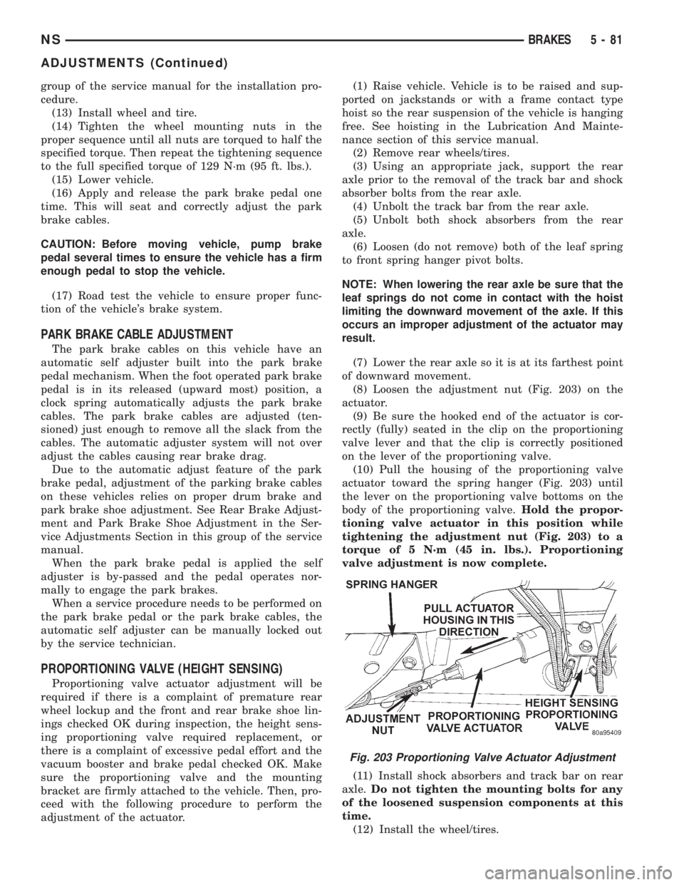
(8) Loosen the adjustment nut (Fig. 203) on the
actuator.
(9) Be sure the hooked end of the actuator is cor-
rectly (fully) seated in the clip on the proportioning
valve lever and that the clip is correctly positioned
on the lever of the proportioning valve.
(10) Pull the housing of the proportioning valve
actuator toward the spring hanger (Fig. 203) until
the lever on the proportioning valve bottoms on the
body of the proportioning valve.Hold the propor-
tioning valve actuator in this position while
tightening the adjustment nut (Fig. 203) to a
torque of 5 N´m (45 in. lbs.). Proportioning
valve adjustment is now complete.
(11) Install shock absorbers and track bar on rear
axle.Do not tighten the mounting bolts for any
of the loosened suspension components at this
time.
(12) Install the wheel/tires.
Fig. 203 Proportioning Valve Actuator Adjustment
NSBRAKES 5 - 81
ADJUSTMENTS (Continued)
Page 164 of 1938
(13) Lower the vehicle to the ground.Be sure
that the suspension is supporting the full
weight of the vehicle.
(14) Tighten the spring to front hanger pivot bolts
to a torque of 156 N´m (115 ft. lbs.).
(15) Tighten the shock absorber mounting bolts to
a torque of 101 N´m (75 ft. lbs.).
(16) Tighten the track bar mounting bolt to a
torque of 95 N´m (70 ft. lbs.).
(17) Road test vehicle to ensure that the prema-
ture rear wheel lockup condition has been corrected.
SPECIFICATIONS
BRAKE FLUID
The brake fluid used in this vehicle must conform
to DOT 3 specifications and SAE J1703 standards.No other type of brake fluid is recommended or
approved for usage in the vehicle brake system. Use
only Mopar brake fluid or an equivalent from a
tightly sealed container.
CAUTION: Never use reclaimed brake fluid or fluid
from an container which has been left open. An
open container will absorb moisture from the air
and contaminate the fluid.
CAUTION: Never use any type of a petroleum-
based fluid in the brake hydraulic system. Use of
such type fluids will result in seal damage of the
vehicle brake hydraulic system causing a failure of
the vehicle brake system. Petroleum based fluids
would be items such as engine oil, transmission
fluid, power steering fluid ect.
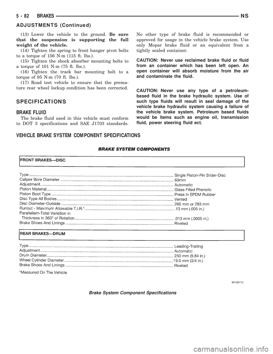
VEHICLE BRAKE SYSTEM COMPONENT SPECIFICATIONS
Brake System Component Specifications
5 - 82 BRAKESNS
ADJUSTMENTS (Continued)
Page 165 of 1938
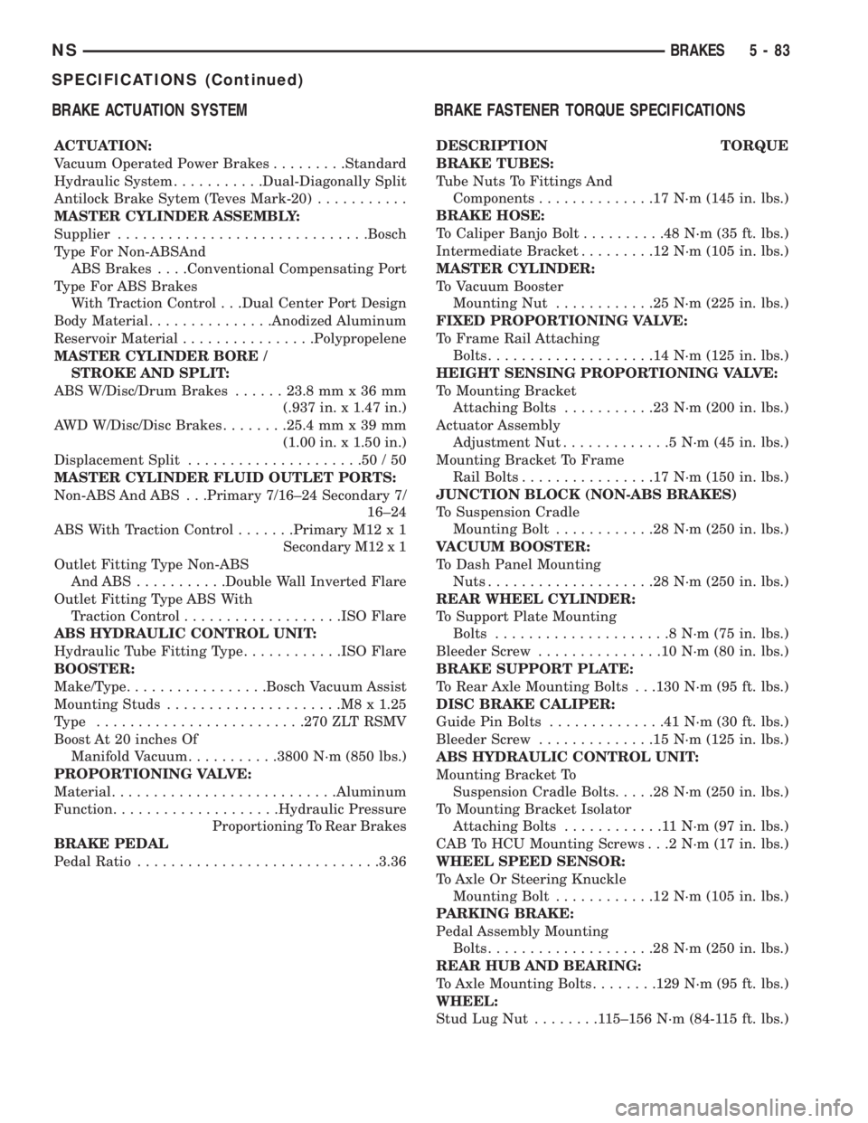
BRAKE ACTUATION SYSTEM
ACTUATION:
Vacuum Operated Power Brakes.........Standard
Hydraulic System...........Dual-Diagonally Split
Antilock Brake Sytem (Teves Mark-20)...........
MASTER CYLINDER ASSEMBLY:
Supplier..............................Bosch
Type For Non-ABSAnd
ABS Brakes. . . .Conventional Compensating Port
Type For ABS Brakes
With Traction Control . . .Dual Center Port Design
Body Material...............Anodized Aluminum
Reservoir Material................Polypropelene
MASTER CYLINDER BORE /
STROKE AND SPLIT:
ABS W/Disc/Drum Brakes......23.8 mm x 36 mm
(.937 in. x 1.47 in.)
AWD W/Disc/Disc Brakes........25.4 mm x 39 mm
(1.00 in. x 1.50 in.)
Displacement Split.....................50/50
MASTER CYLINDER FLUID OUTLET PORTS:
Non-ABS And ABS . . .Primary 7/16±24 Secondary 7/
16±24
ABS With Traction Control.......Primary M12 x 1
Secondary M12 x 1
Outlet Fitting Type Non-ABS
AndABS...........Double Wall Inverted Flare
Outlet Fitting Type ABS With
Traction Control...................ISO Flare
ABS HYDRAULIC CONTROL UNIT:
Hydraulic Tube Fitting Type............ISO Flare
BOOSTER:
Make/Type.................Bosch Vacuum Assist
Mounting Studs.....................M8x1.25
Type .........................270 ZLT RSMV
Boost At 20 inches Of
Manifold Vacuum...........3800 N´m (850 lbs.)
PROPORTIONING VALVE:
Material...........................Aluminum
Function....................Hydraulic Pressure
Proportioning To Rear Brakes
BRAKE PEDAL
Pedal Ratio.............................3.36
BRAKE FASTENER TORQUE SPECIFICATIONS
DESCRIPTION TORQUE
BRAKE TUBES:
Tube Nuts To Fittings And
Components..............17N´m(145 in. lbs.)
BRAKE HOSE:
To Caliper Banjo Bolt..........48N´m(35ft.lbs.)
Intermediate Bracket.........12N´m(105 in. lbs.)
MASTER CYLINDER:
To Vacuum Booster
Mounting Nut............25N´m(225 in. lbs.)
FIXED PROPORTIONING VALVE:
To Frame Rail Attaching
Bolts....................14N´m(125 in. lbs.)
HEIGHT SENSING PROPORTIONING VALVE:
To Mounting Bracket
Attaching Bolts...........23N´m(200 in. lbs.)
Actuator Assembly
Adjustment Nut.............5N´m(45in.lbs.)
Mounting Bracket To Frame
Rail Bolts................17N´m(150 in. lbs.)
JUNCTION BLOCK (NON-ABS BRAKES)
To Suspension Cradle
Mounting Bolt............28N´m(250 in. lbs.)
VACUUM BOOSTER:
To Dash Panel Mounting
Nuts....................28N´m(250 in. lbs.)
REAR WHEEL CYLINDER:
To Support Plate Mounting
Bolts.....................8N´m(75in.lbs.)
Bleeder Screw...............10N´m(80in.lbs.)
BRAKE SUPPORT PLATE:
To Rear Axle Mounting Bolts . . .130 N´m (95 ft. lbs.)
DISC BRAKE CALIPER:
Guide Pin Bolts..............41N´m(30ft.lbs.)
Bleeder Screw..............15N´m(125 in. lbs.)
ABS HYDRAULIC CONTROL UNIT:
Mounting Bracket To
Suspension Cradle Bolts.....28N´m(250 in. lbs.)
To Mounting Bracket Isolator
Attaching Bolts............11N´m(97in.lbs.)
CAB To HCU Mounting Screws . . .2 N´m (17 in. lbs.)
WHEEL SPEED SENSOR:
To Axle Or Steering Knuckle
Mounting Bolt............12N´m(105 in. lbs.)
PARKING BRAKE:
Pedal Assembly Mounting
Bolts....................28N´m(250 in. lbs.)
REAR HUB AND BEARING:
To Axle Mounting Bolts........129 N´m (95 ft. lbs.)
WHEEL:
Stud Lug Nut........115±156 N´m (84-115 ft. lbs.)
NSBRAKES 5 - 83
SPECIFICATIONS (Continued)
Page 166 of 1938
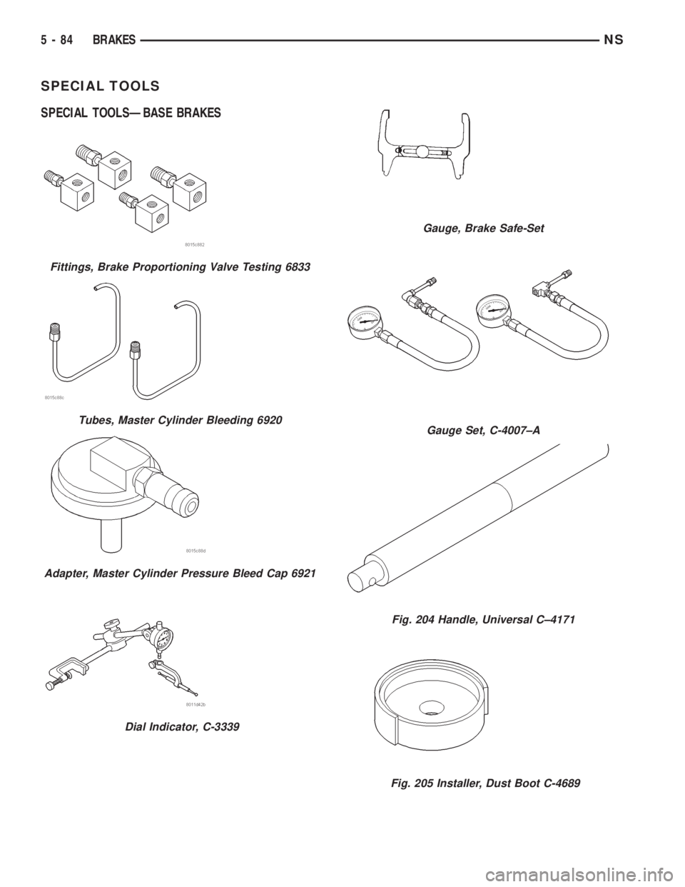
SPECIAL TOOLS
SPECIAL TOOLSÐBASE BRAKES
Fittings, Brake Proportioning Valve Testing 6833
Tubes, Master Cylinder Bleeding 6920
Adapter, Master Cylinder Pressure Bleed Cap 6921
Dial Indicator, C-3339
Gauge, Brake Safe-Set
Gauge Set, C-4007±A
Fig. 204 Handle, Universal C±4171
Fig. 205 Installer, Dust Boot C-4689
5 - 84 BRAKESNS
Page 167 of 1938
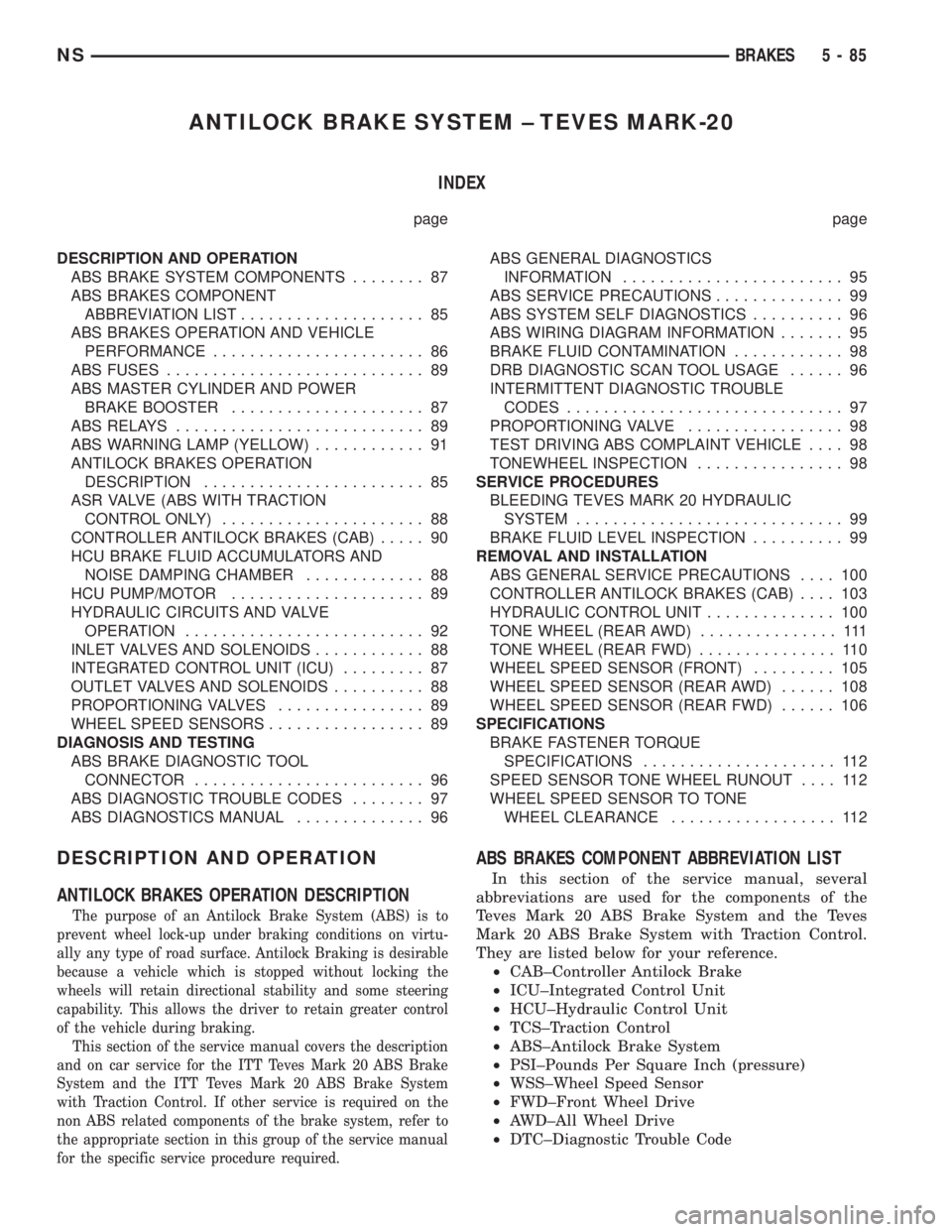
ANTILOCK BRAKE SYSTEM ± TEVES MARK-20
INDEX
page page
DESCRIPTION AND OPERATION
ABS BRAKE SYSTEM COMPONENTS........ 87
ABS BRAKES COMPONENT
ABBREVIATION LIST.................... 85
ABS BRAKES OPERATION AND VEHICLE
PERFORMANCE....................... 86
ABS FUSES............................ 89
ABS MASTER CYLINDER AND POWER
BRAKE BOOSTER..................... 87
ABS RELAYS........................... 89
ABS WARNING LAMP (YELLOW)............ 91
ANTILOCK BRAKES OPERATION
DESCRIPTION........................ 85
ASR VALVE (ABS WITH TRACTION
CONTROL ONLY)...................... 88
CONTROLLER ANTILOCK BRAKES (CAB)..... 90
HCU BRAKE FLUID ACCUMULATORS AND
NOISE DAMPING CHAMBER............. 88
HCU PUMP/MOTOR..................... 89
HYDRAULIC CIRCUITS AND VALVE
OPERATION.......................... 92
INLET VALVES AND SOLENOIDS............ 88
INTEGRATED CONTROL UNIT (ICU)......... 87
OUTLET VALVES AND SOLENOIDS.......... 88
PROPORTIONING VALVES................ 89
WHEEL SPEED SENSORS................. 89
DIAGNOSIS AND TESTING
ABS BRAKE DIAGNOSTIC TOOL
CONNECTOR......................... 96
ABS DIAGNOSTIC TROUBLE CODES........ 97
ABS DIAGNOSTICS MANUAL.............. 96ABS GENERAL DIAGNOSTICS
INFORMATION........................ 95
ABS SERVICE PRECAUTIONS.............. 99
ABS SYSTEM SELF DIAGNOSTICS.......... 96
ABS WIRING DIAGRAM INFORMATION....... 95
BRAKE FLUID CONTAMINATION............ 98
DRB DIAGNOSTIC SCAN TOOL USAGE...... 96
INTERMITTENT DIAGNOSTIC TROUBLE
CODES.............................. 97
PROPORTIONING VALVE................. 98
TEST DRIVING ABS COMPLAINT VEHICLE.... 98
TONEWHEEL INSPECTION................ 98
SERVICE PROCEDURES
BLEEDING TEVES MARK 20 HYDRAULIC
SYSTEM............................. 99
BRAKE FLUID LEVEL INSPECTION.......... 99
REMOVAL AND INSTALLATION
ABS GENERAL SERVICE PRECAUTIONS.... 100
CONTROLLER ANTILOCK BRAKES (CAB).... 103
HYDRAULIC CONTROL UNIT.............. 100
TONE WHEEL (REAR AWD)............... 111
TONE WHEEL (REAR FWD)............... 110
WHEEL SPEED SENSOR (FRONT)......... 105
WHEEL SPEED SENSOR (REAR AWD)...... 108
WHEEL SPEED SENSOR (REAR FWD)...... 106
SPECIFICATIONS
BRAKE FASTENER TORQUE
SPECIFICATIONS..................... 112
SPEED SENSOR TONE WHEEL RUNOUT.... 112
WHEEL SPEED SENSOR TO TONE
WHEEL CLEARANCE.................. 112
DESCRIPTION AND OPERATION
ANTILOCK BRAKES OPERATION DESCRIPTION
The purpose of an Antilock Brake System (ABS) is to
prevent wheel lock-up under braking conditions on virtu-
ally any type of road surface. Antilock Braking is desirable
because a vehicle which is stopped without locking the
wheels will retain directional stability and some steering
capability. This allows the driver to retain greater control
of the vehicle during braking.
This section of the service manual covers the description
and on car service for the ITT Teves Mark 20 ABS Brake
System and the ITT Teves Mark 20 ABS Brake System
with Traction Control. If other service is required on the
non ABS related components of the brake system, refer to
the appropriate section in this group of the service manual
for the specific service procedure required.
ABS BRAKES COMPONENT ABBREVIATION LIST
In this section of the service manual, several
abbreviations are used for the components of the
Teves Mark 20 ABS Brake System and the Teves
Mark 20 ABS Brake System with Traction Control.
They are listed below for your reference.
²CAB±Controller Antilock Brake
²ICU±Integrated Control Unit
²HCU±Hydraulic Control Unit
²TCS±Traction Control
²ABS±Antilock Brake System
²PSI±Pounds Per Square Inch (pressure)
²WSS±Wheel Speed Sensor
²FWD±Front Wheel Drive
²AWD±All Wheel Drive
²DTC±Diagnostic Trouble Code
NSBRAKES 5 - 85
Page 168 of 1938
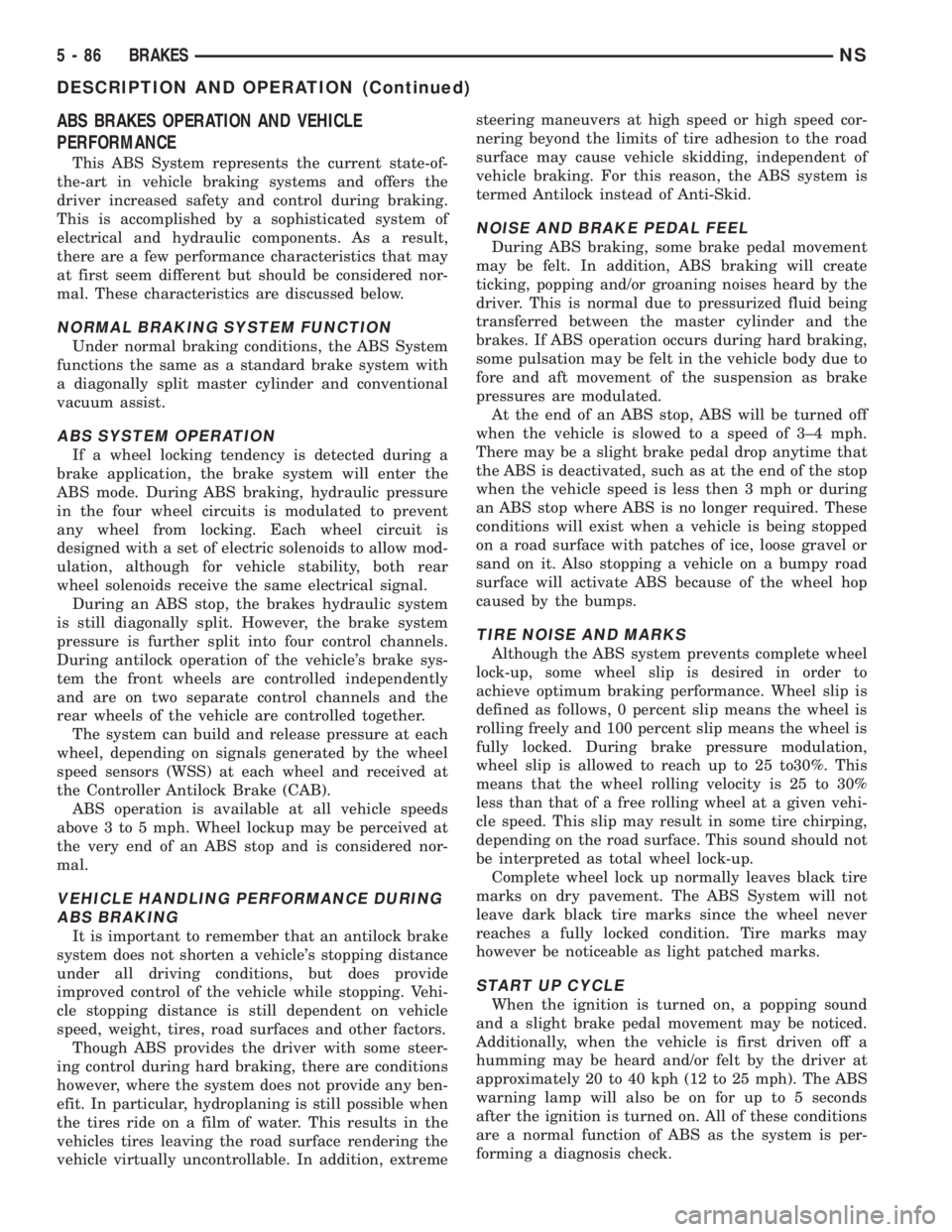
ABS BRAKES OPERATION AND VEHICLE
PERFORMANCE
This ABS System represents the current state-of-
the-art in vehicle braking systems and offers the
driver increased safety and control during braking.
This is accomplished by a sophisticated system of
electrical and hydraulic components. As a result,
there are a few performance characteristics that may
at first seem different but should be considered nor-
mal. These characteristics are discussed below.
NORMAL BRAKING SYSTEM FUNCTION
Under normal braking conditions, the ABS System
functions the same as a standard brake system with
a diagonally split master cylinder and conventional
vacuum assist.
ABS SYSTEM OPERATION
If a wheel locking tendency is detected during a
brake application, the brake system will enter the
ABS mode. During ABS braking, hydraulic pressure
in the four wheel circuits is modulated to prevent
any wheel from locking. Each wheel circuit is
designed with a set of electric solenoids to allow mod-
ulation, although for vehicle stability, both rear
wheel solenoids receive the same electrical signal.
During an ABS stop, the brakes hydraulic system
is still diagonally split. However, the brake system
pressure is further split into four control channels.
During antilock operation of the vehicle's brake sys-
tem the front wheels are controlled independently
and are on two separate control channels and the
rear wheels of the vehicle are controlled together.
The system can build and release pressure at each
wheel, depending on signals generated by the wheel
speed sensors (WSS) at each wheel and received at
the Controller Antilock Brake (CAB).
ABS operation is available at all vehicle speeds
above 3 to 5 mph. Wheel lockup may be perceived at
the very end of an ABS stop and is considered nor-
mal.
VEHICLE HANDLING PERFORMANCE DURING
ABS BRAKING
It is important to remember that an antilock brake
system does not shorten a vehicle's stopping distance
under all driving conditions, but does provide
improved control of the vehicle while stopping. Vehi-
cle stopping distance is still dependent on vehicle
speed, weight, tires, road surfaces and other factors.
Though ABS provides the driver with some steer-
ing control during hard braking, there are conditions
however, where the system does not provide any ben-
efit. In particular, hydroplaning is still possible when
the tires ride on a film of water. This results in the
vehicles tires leaving the road surface rendering the
vehicle virtually uncontrollable. In addition, extremesteering maneuvers at high speed or high speed cor-
nering beyond the limits of tire adhesion to the road
surface may cause vehicle skidding, independent of
vehicle braking. For this reason, the ABS system is
termed Antilock instead of Anti-Skid.
NOISE AND BRAKE PEDAL FEEL
During ABS braking, some brake pedal movement
may be felt. In addition, ABS braking will create
ticking, popping and/or groaning noises heard by the
driver. This is normal due to pressurized fluid being
transferred between the master cylinder and the
brakes. If ABS operation occurs during hard braking,
some pulsation may be felt in the vehicle body due to
fore and aft movement of the suspension as brake
pressures are modulated.
At the end of an ABS stop, ABS will be turned off
when the vehicle is slowed to a speed of 3±4 mph.
There may be a slight brake pedal drop anytime that
the ABS is deactivated, such as at the end of the stop
when the vehicle speed is less then 3 mph or during
an ABS stop where ABS is no longer required. These
conditions will exist when a vehicle is being stopped
on a road surface with patches of ice, loose gravel or
sand on it. Also stopping a vehicle on a bumpy road
surface will activate ABS because of the wheel hop
caused by the bumps.
TIRE NOISE AND MARKS
Although the ABS system prevents complete wheel
lock-up, some wheel slip is desired in order to
achieve optimum braking performance. Wheel slip is
defined as follows, 0 percent slip means the wheel is
rolling freely and 100 percent slip means the wheel is
fully locked. During brake pressure modulation,
wheel slip is allowed to reach up to 25 to30%. This
means that the wheel rolling velocity is 25 to 30%
less than that of a free rolling wheel at a given vehi-
cle speed. This slip may result in some tire chirping,
depending on the road surface. This sound should not
be interpreted as total wheel lock-up.
Complete wheel lock up normally leaves black tire
marks on dry pavement. The ABS System will not
leave dark black tire marks since the wheel never
reaches a fully locked condition. Tire marks may
however be noticeable as light patched marks.
START UP CYCLE
When the ignition is turned on, a popping sound
and a slight brake pedal movement may be noticed.
Additionally, when the vehicle is first driven off a
humming may be heard and/or felt by the driver at
approximately 20 to 40 kph (12 to 25 mph). The ABS
warning lamp will also be on for up to 5 seconds
after the ignition is turned on. All of these conditions
are a normal function of ABS as the system is per-
forming a diagnosis check.
5 - 86 BRAKESNS
DESCRIPTION AND OPERATION (Continued)
Page 169 of 1938
PREMATURE ABS CYCLING
NOTE: When working on a vehicle which has a
complaint of premature ABS cycling it may be nec-
essary to use a DRB Scan Tool to detect and verify
the condition.
There is one complaint called Premature ABS
Cycling in which neither the Red Brake Warning
Lamp nor the Amber Antilock Lamp were illumi-
nated and no fault codes were stored in the CAB.
Symptoms of Premature ABS Cycling, include click-
ing sounds from the solenoids valves, pump motor
running and pulsations in the brake pedal. This con-
dition can occur at any braking rate of the vehicle
and on any type of road surface. This creates an
additional condition which needs to be correctly
assessed when diagnosing problems with the antilock
brake system.
The following conditions are common causes that
need to be checked when diagnosing a condition of
Premature ABS Cycling. Damaged tone wheels,
incorrect tone wheels, damage to a wheel speed sen-
sor mounting boss on a steering knuckle, a loose
wheel speed sensor mounting bolt, and excessive tone
wheel runout. Also, an excessively large tone wheel
to wheel speed sensor air gap can lead to the condi-
tion of Premature ABS Cycling. Special attention is
to be given to these components when diagnosing a
vehicle exhibiting the condition of Premature ABS
Cycling. After diagnosing the defective component,
repair or replace as required.
When the component repair or replacement is com-
pleted, test drive the vehicle to verify the condition of
Premature ABS Cycling has been corrected.
ABS BRAKE SYSTEM COMPONENTS
The following is a detailed description of the Teves
Mark 20 ABS brake system components. For infor-
mation on servicing the base brake system compo-
nents, see the base Brake System section of this
Service Manual.
ABS MASTER CYLINDER AND POWER BRAKE
BOOSTER
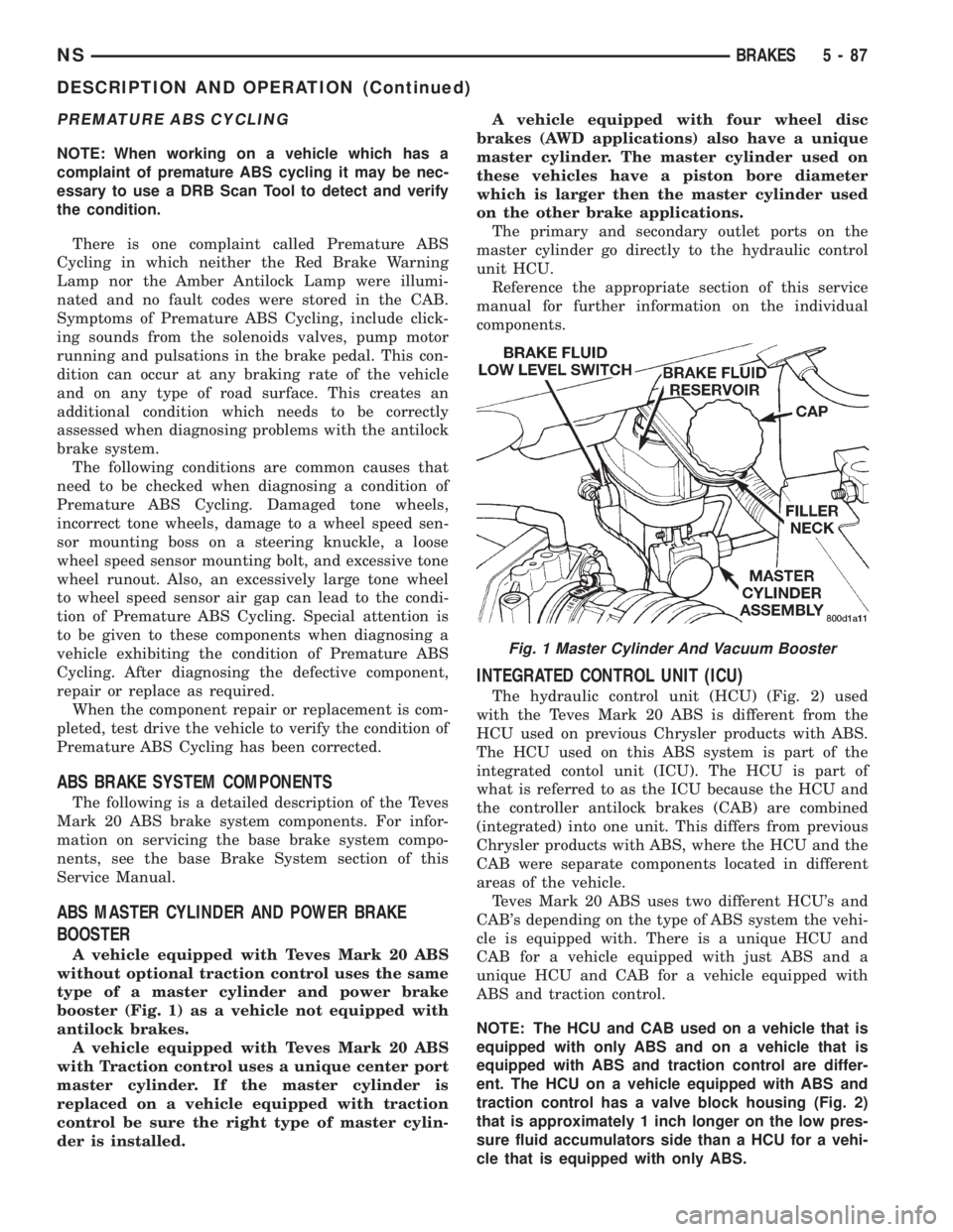
A vehicle equipped with Teves Mark 20 ABS
without optional traction control uses the same
type of a master cylinder and power brake
booster (Fig. 1) as a vehicle not equipped with
antilock brakes.
A vehicle equipped with Teves Mark 20 ABS
with Traction control uses a unique center port
master cylinder. If the master cylinder is
replaced on a vehicle equipped with traction
control be sure the right type of master cylin-
der is installed.A vehicle equipped with four wheel disc
brakes (AWD applications) also have a unique
master cylinder. The master cylinder used on
these vehicles have a piston bore diameter
which is larger then the master cylinder used
on the other brake applications.
The primary and secondary outlet ports on the
master cylinder go directly to the hydraulic control
unit HCU.
Reference the appropriate section of this service
manual for further information on the individual
components.
INTEGRATED CONTROL UNIT (ICU)
The hydraulic control unit (HCU) (Fig. 2) used
with the Teves Mark 20 ABS is different from the
HCU used on previous Chrysler products with ABS.
The HCU used on this ABS system is part of the
integrated contol unit (ICU). The HCU is part of
what is referred to as the ICU because the HCU and
the controller antilock brakes (CAB) are combined
(integrated) into one unit. This differs from previous
Chrysler products with ABS, where the HCU and the
CAB were separate components located in different
areas of the vehicle.
Teves Mark 20 ABS uses two different HCU's and
CAB's depending on the type of ABS system the vehi-
cle is equipped with. There is a unique HCU and
CAB for a vehicle equipped with just ABS and a
unique HCU and CAB for a vehicle equipped with
ABS and traction control.
NOTE: The HCU and CAB used on a vehicle that is
equipped with only ABS and on a vehicle that is
equipped with ABS and traction control are differ-
ent. The HCU on a vehicle equipped with ABS and
traction control has a valve block housing (Fig. 2)
that is approximately 1 inch longer on the low pres-
sure fluid accumulators side than a HCU for a vehi-
cle that is equipped with only ABS.
Fig. 1 Master Cylinder And Vacuum Booster
NSBRAKES 5 - 87
DESCRIPTION AND OPERATION (Continued)
Page 170 of 1938
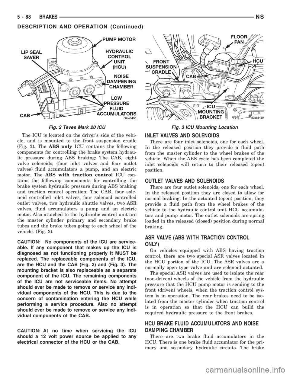
The ICU is located on the driver's side of the vehi-
cle, and is mounted to the front suspension cradle
(Fig. 3). TheABS onlyICU contains the following
components for controlling the brake system hydrau-
lic pressure during ABS braking: The CAB, eight
valve solenoids, (four inlet valves and four outlet
valves) fluid accumulators a pump, and an electric
motor. TheABS with traction controlICU con-
tains the following components for controlling the
brake system hydraulic pressure during ABS braking
and traction control operation: The CAB, four sole-
noid controlled inlet valves, four solenoid controlled
outlet valves, two hydraulic shuttle valves, two ASR
valves, fluid accumulators a pump and an electric
motor. Also attached to the hydraulic control unit are
the master cylinder primary and secondary brake
tubes and the brake tubes going to each wheel of the
vehicle. (Fig. 3).
CAUTION: No components of the ICU are service-
able. If any component that makes up the ICU is
diagnosed as not functioning properly it MUST be
replaced. The replaceable components of the ICU,
are the HCU and the CAB (Fig. 2) and (Fig. 3). The
mounting bracket is also replaceable as a separate
component of the ICU. The remaining components
of the ICU are not serviceable items. No attempt
should ever be made to remove or service any indi-
vidual components of the HCU. This is due to the
concern of contamination entering the HCU while
performing a service procedure. Also no attempt
should ever be made to remove or service any indi-
vidual components of the CAB.
CAUTION: At no time when servicing the ICU
should a 12 volt power source be applied to any
electrical connector of the HCU or the CAB.INLET VALVES AND SOLENOIDS
There are four inlet solenoids, one for each wheel.
In the released position they provide a fluid path
from the master cylinder to the wheel brakes of the
vehicle. When the ABS cycle has been completed the
inlet solenoids will return to their released (open)
position.
OUTLET VALVES AND SOLENOIDS
There are four outlet solenoids, one for each wheel.
In the released position they are closed to allow for
normal braking. In the actuated (open) position, they
provide a fluid path from the wheel brakes of the
vehicle to the hydraulic control unit HCU accumula-
tors and pump motor. The outlet solenoids are spring
loaded in the released (closed) position during normal
braking.
ASR VALVE (ABS WITH TRACTION CONTROL
ONLY)
On vehicles equipped with ABS having traction
control, there are two special ASR valves located in
the HCU portion of the ICU. The ASR valves are a
normally open type valve and are solenoid actuated.
The special ASR valves are used to isolate the rear
(non-driven) wheels of the vehicle from the hydraulic
pressure that the HCU pump motor is sending to the
front (driven) wheels, when the traction control sys-
tem is in operation. The rear brakes need to be iso-
lated from the master cylinder when traction control
is in operation so that the HCU can build the
required hydraulic pressure to the front brakes.
HCU BRAKE FLUID ACCUMULATORS AND NOISE
DAMPING CHAMBER
There are two brake fluid accumulators in the
HCU. There is one brake fluid accumlator for the pri-
mary and secondary hydraulic circuits. The brake
Fig. 2 Teves Mark 20 ICUFig. 3 ICU Mounting Location
5 - 88 BRAKESNS
DESCRIPTION AND OPERATION (Continued)