CHRYSLER VOYAGER 1996 Service Manual
Manufacturer: CHRYSLER, Model Year: 1996, Model line: VOYAGER, Model: CHRYSLER VOYAGER 1996Pages: 1938, PDF Size: 55.84 MB
Page 131 of 1938

(7) Install aNEWvacuum seal on mounting flange
of master cylinder (Fig. 110).
(8) Position master cylinder on studs of vacuum
booster aligning push rod on vacuum booster with
master cylinder piston.
(9) Install the 2 nuts (Fig. 107) mounting the mas-
ter cylinder to the vacuum booster. Tighten the
mounting nuts to a torque of 25 N´m (225 in. lbs.).
(10) Install the wiper module drain hose (Fig. 107)
on the wiper module. Install the tie strap attaching
the wiper module drain hose to the brake tube at the
master cylinder.Tie strap should be loosely tight-
ened so as not to collapse the wiper module
drain hose.
(11) Install the wiring harness connector on the
brake fluid level sensor in the master cylinder fluid
reservoir (Fig. 106).
(12) Install the battery tray in the vehicle. Install
the 2 bolts and the nut (Fig. 105) attaching the bat-
tery tray. Tighten the 2 bolts and the nut to a torque
of 14 N´m (125 in lbs.).(13) If vehicle is equipped with speed control,
install the speed control servo and bracket on the
battery tray. Install and securely tighten bolt attach-
ing bracket to battery tray.
(14) If vehicle is equipped with speed control,
install the wiring harness connector on the speed
control servo. Then connect the vacuum lines onto
the speed control servo and vacuum reservoir on bat-
tery tray.
(15) Install the air inlet resonator and hoses as an
assembly on the throttle body and air cleaner hous-
ing (Fig. 104). Securely tighten the hose clamp at the
air cleaner housing and throttle body.
(16) Install the battery and the battery thermal
guard.
(17) Install the battery cables on the battery.
(18) Check the operation of the stop lamp switch
and adjust if necessary.
VACUUM BOOSTER 3.0 LITER ENGINE
REMOVE
CAUTION: Stored vacuum in the vacuum booster
must be pumped down (removed) before removing
master cylinder from power brake booster. This is
necessary to prevent the power brake booster from
sucking in any contamination as the master cylin-
der is removed. This can be done simply by pump-
ing the brake pedal, with the vehicle's engine not
running, until a firm feeling brake pedal is achieved.
(1) With engine not running, pump the brake
pedal until a firm pedal is achieved (4-5 strokes).
(2) Remove both battery cables from battery.
(3) Remove the battery thermal guard and the bat-
tery from the battery tray.
(4) Remove the air inlet resonator and hoses as an
assembly from the throttle body and air cleaner
housing (Fig. 111)
(5) If vehicle is equipped with speed control,
unplug wiring harness connector from the speed con-
trol servo. Then disconnect vacuum lines from the
speed control servo and vacuum reservoir on battery
tray.
(6) Remove bolt attaching the speed control servo
bracket to the battery tray. Slide the bracket forward
to unhook it from the battery tray and remove.
(7) Remove the 2 bolts and the nut (Fig. 112)
attaching the battery tray to the body of the vehicle.
(8) Remove wiring harness connector from brake
fluid level sensor in master cylinder fluid reservoir
(Fig. 113).
(9) Clean the area where the master cylinder
assembly attaches to the power brake booster. Use
only a solvent such as Mopar Brake Parts Cleaner or
an equivalent.
Fig. 109 Retaining Clip Installed On Brake Pedal Pin
Fig. 110 Vacuum Seal Installed On Master Cylinder
NSBRAKES 5 - 49
REMOVAL AND INSTALLATION (Continued)
Page 132 of 1938

(10) Remove clip attaching drain hose to brake
tube at master cylinder. Remove drain hose (Fig. 114)
from wiper module. Remove the 2 nuts attaching the
master cylinder assembly to the power brake vacuum
booster (Fig. 114).
NOTE: It is not necessary to remove the brake
tubes from the master cylinder when removing the
master cylinder from the power brake vacuum
booster.
(11) Remove the master cylinder and the brake
tubes as an assembly from power brake vacuum
booster. When master cylinder is removed, lay it out
of the way on top of the left motor mount(12) Disconnect vacuum hose from check valve
located on power brake vacuum booster.DO NOT
REMOVE CHECK VALVE FROM POWER
BRAKE BOOSTER.
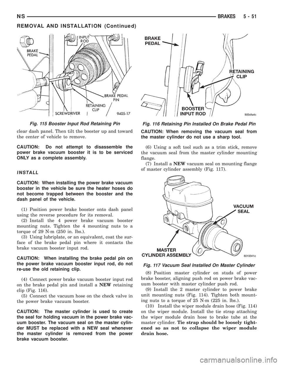
(13) Locate the power brake vacuum booster input
rod to brake pedal attachment under instrument
panel. Position a small screwdriver between the cen-
ter tang on the power brake booster input rod to
brake pedal pin retaining clip (Fig. 115).
(14) Rotate screwdriver enough to allow retaining
clip center tang to pass over end of brake pedal pin.
Then pull retaining clip off brake pedal pin.Discard
retaining clip. It is not to be reused. Replace
only with a new retaining clip when assembled.
(15) Remove the 4 nuts attaching the vacuum
booster to the dash panel. Nuts are accessible from
under dash panel in area of the steering column and
pedal bracket assembly.
(16) From outside the vehicle, slide power brake
vacuum booster forward until its mounting studs
Fig. 111 Air Inlet Resonator
Fig. 112 Battery Tray Mounting Locations
Fig. 113 Electrical Connection To Fluid Level Sensor
Fig. 114 Master Cylinder Attachment To Power
Brake Vacuum Booster
5 - 50 BRAKESNS
REMOVAL AND INSTALLATION (Continued)
Page 133 of 1938
clear dash panel. Then tilt the booster up and toward
the center of vehicle to remove.
CAUTION: Do not attempt to disassemble the
power brake vacuum booster it is to be serviced
ONLY as a complete assembly.
INSTALL
CAUTION: When installing the power brake vacuum
booster in the vehicle be sure the heater hoses do
not become trapped between the booster and the
dash panel of the vehicle.
(1) Position power brake booster onto dash panel
using the reverse procedure for its removal.
(2) Install the 4 power brake vacuum booster
mounting nuts. Tighten the 4 mounting nuts to a
torque of 29 N´m (250 in. lbs.).
(3) Using lubriplate, or an equivalent, coat the sur-
face of the brake pedal pin where it contacts the
brake vacuum booster input rod.
CAUTION: When installing the brake pedal pin on
the power brake vacuum booster input rod, do not
re-use the old retaining clip.
(4) Connect power brake vacuum booster input rod
on the brake pedal pin and install aNEWretaining
clip (Fig. 116).
(5) Connect the vacuum hose on the check valve in
the power brake vacuum booster.
CAUTION: The master cylinder is used to create
the seal for holding vacuum in the power brake vac-
uum booster. The vacuum seal on the master cylin-
der MUST be replaced with a NEW seal whenever
the master cylinder is removed from the power
brake vacuum booster.CAUTION: When removing the vacuum seal from
the master cylinder do not use a sharp tool.
(6) Using a soft tool such as a trim stick, remove
the vacuum seal from the master cylinder mounting
flange.
(7) Install aNEWvacuum seal on mounting flange
of master cylinder assembly (Fig. 117).
(8) Position master cylinder on studs of power
brake booster, aligning push rod on power brake vac-
uum booster with master cylinder push rod.
(9) Install the 2 master cylinder to power brake
unit mounting nuts (Fig. 114). Tighten both mount-
ing nuts to a torque of 25 N´m (225 in. lbs.).
(10) Install the wiper module drain hose (Fig. 114)
on the wiper module. Install the tie strap attaching
the wiper module drain hose to brake tube at the
master cylinder.Tie strap should be loosely tight-
ened so as not to collapse the wiper module
drain hose.
Fig. 115 Booster Input Rod Retaining PinFig. 116 Retaining Pin Installed On Brake Pedal Pin
Fig. 117 Vacuum Seal Installed On Master Cylinder
NSBRAKES 5 - 51
REMOVAL AND INSTALLATION (Continued)
Page 134 of 1938

(11) Install the wiring harness connector on the
brake fluid level sensor in the master cylinder fluid
reservoir (Fig. 113).
(12) Install the battery tray in the vehicle. Install
the 2 bolts and the nut (Fig. 112) attaching the bat-
tery tray to the vehicle. Tighten the 2 bolts and the
nut to a torque of 14 N´m (125 in lbs.).
(13) If vehicle is equipped with speed control,
install the speed control servo and bracket on the
battery tray. Install and securely tighten bolt attach-
ing bracket to battery tray.
(14) If vehicle is equipped with speed control,
install the wiring harness connector on the speed
control servo. Then connect the vacuum lines onto
the speed control servo and vacuum reservoir on bat-
tery tray.
(15) Install the air inlet resonator and hoses as an
assembly on the throttle body and air cleaner hous-
ing (Fig. 111). Securely tighten the hose clamp at the
air cleaner housing and throttle body.
(16) Install the battery and the battery thermal
guard.
(17) Install the battery cables on the battery.
(18) Check the operation of the stop lamp switch
and adjust if necessary.
VACUUM BOOSTER 3.3/3.8 LITER ENGINE
REMOVE
CAUTION: Reserve vacuum in the vacuum booster
must be pumped down (removed) before removing
master cylinder from vacuum booster. This is nec-
essary to prevent the vacuum booster from sucking
in any contamination as the master cylinder is
removed. This can be done simply by pumping the
brake pedal, with the vehicle's engine not running,
until a firm feeling brake pedal is achieved.
(1) With engine not running, pump the brake
pedal until a firm pedal is achieved (4-5 strokes).
(2) Remove both battery cables from battery.
(3) Remove the battery thermal guard and the bat-
tery from the battery tray.
(4) Remove the air inlet resonator and hoses as an
assembly from the throttle body and air cleaner
housing (Fig. 118)
(5) If vehicle is equipped with speed control,
unplug wiring harness connector from the speed con-
trol servo. Then disconnect vacuum lines from the
speed control servo and vacuum reservoir on battery
tray.
(6) Remove bolt attaching the speed control servo
bracket to the battery tray. Slide the bracket forward
to unhook it from the battery tray and remove.
(7) Remove the 2 bolts and the nut (Fig. 119)
attaching the battery tray to the body of the vehicle.(8) Remove the wiring harness connector (Fig. 120)
from the EGR valve transducer.
(9) Remove wiring harness connectors from throt-
tle position sensor and AIS motor on throttle body
(Fig. 121).
(10) Remove the 2 bolts (Fig. 122) attaching the
throttle body to the intake manifold and the clip (Fig.
122) attaching the wiring harness to the throttle
cable bracket. Then remove the throttle body and
throttle cable bracket as an assembly from the intake
manifold.
(11) Remove wiring harness connector from brake
fluid level sensor in master cylinder fluid reservoir
(Fig. 123).
(12) Clean the area where the master cylinder
assembly attaches to the power brake booster. Use
Fig. 118 Air Inlet Resonator
Fig. 119 Battery Tray Mounting Locations
5 - 52 BRAKESNS
REMOVAL AND INSTALLATION (Continued)
Page 135 of 1938

only a solvent such as Mopar Brake Parts Cleaner or
an equivalent.
(13) Remove clip, attaching drain hose for wiper
module to brake tube at master cylinder. Remove
drain hose (Fig. 124) from wiper module. Remove the
2 nuts, attaching the master cylinder to the vacuum
booster (Fig. 124).
NOTE: It is not necessary to remove the brake
tubes from the master cylinder when removing the
master cylinder from the vacuum booster.
(14) Remove master cylinder and brake tubes as
an assembly from the vacuum booster. When mastercylinder is removed, lay it out of the way on top of
the left motor mount
Fig. 120 Electrical Connector At EGR Transducer
Fig. 121 Electrical And Vacuum Connections To
Throttle Body
Fig. 122 Throttle Body Attachment To Intake
Manifold
Fig. 123 Fluid Level Sensor Electrical Connection
Fig. 124 Master Cylinder Attachment To Vacuum
Booster
NSBRAKES 5 - 53
REMOVAL AND INSTALLATION (Continued)
Page 136 of 1938
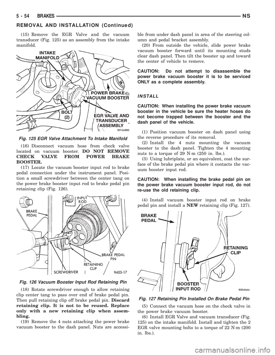
(15) Remove the EGR Valve and the vacuum
transducer (Fig. 125) as an assembly from the intake
manifold.
(16) Disconnect vacuum hose from check valve
located on vacuum booster.DO NOT REMOVE
CHECK VALVE FROM POWER BRAKE
BOOSTER.
(17) Locate the vacuum booster input rod to brake
pedal connection under the instrument panel. Posi-
tion a small screwdriver between the center tang on
the power brake booster input rod to brake pedal pin
retaining clip (Fig. 126).
(18) Rotate screwdriver enough to allow retaining
clip center tang to pass over end of brake pedal pin.
Then pull retaining clip off brake pedal pin.Discard
retaining clip. It is not to be reused. Replace
only with a new retaining clip when assem-
bling.
(19) Remove the 4 nuts attaching the power brake
vacuum booster to the dash panel. Nuts are accessi-ble from under dash panel in area of the steering col-
umn and pedal bracket assembly.
(20) From outside the vehicle, slide power brake
vacuum booster forward until its mounting studs
clear dash panel. Then tilt the booster up and toward
the center of vehicle to remove.
CAUTION: Do not attempt to disassemble the
power brake vacuum booster it is to be serviced
ONLY as a complete assembly.
INSTALL
CAUTION: When installing the power brake vacuum
booster in the vehicle be sure the heater hoses do
not become trapped between the booster and the
dash panel of the vehicle.
(1) Position vacuum booster on dash panel using
the reverse procedure of its removal.
(2) Install the 4 nuts mounting the vacuum
booster to the dash panel. Tighten the 4 mounting
nuts to a torque of 29 N´m (250 in. lbs.).
(3) Using lubriplate, or an equivalent, coat the sur-
face of the brake pedal pin where it contacts the vac-
uum booster input rod.
CAUTION: When installing the brake pedal pin on
the power brake vacuum booster input rod, do not
re-use the old retaining clip.
(4) Install vacuum booster input rod on brake
pedal pin and install aNEWretaining clip (Fig. 127).
(5) Connect the vacuum hose on the check valve in
the power brake vacuum booster.
(6) Install EGR Valve and vacuum transducer (Fig.
125) on the intake manifold. Install and tighten the 2
EGR valve mounting bolts to a torque of 22 N´m (200
in. lbs.).
Fig. 125 EGR Valve Attachment To Intake Manifold
Fig. 126 Vacuum Booster Input Rod Retaining Pin
Fig. 127 Retaining Pin Installed On Brake Pedal Pin
5 - 54 BRAKESNS
REMOVAL AND INSTALLATION (Continued)
Page 137 of 1938
CAUTION: The master cylinder is used to create
the seal for holding vacuum in the vacuum booster.
The vacuum seal on the master cylinder MUST be
replaced with a NEW seal whenever the master cyl-
inder is removed from the vacuum booster.
CAUTION: When removing the vacuum seal from
the master cylinder do not use a sharp tool.
(7) Using a soft tool such as a trim stick, remove
the vacuum seal from the master cylinder mounting
flange.
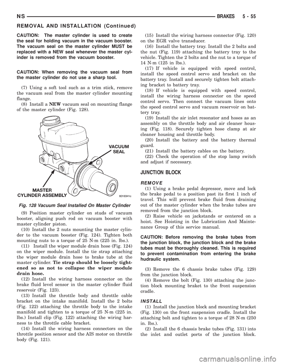
(8) Install aNEWvacuum seal on mounting flange
of the master cylinder (Fig. 128).
(9) Position master cylinder on studs of vacuum
booster, aligning push rod on vacuum booster with
master cylinder piston.
(10) Install the 2 nuts mounting the master cylin-
der to the vacuum booster (Fig. 124). Tighten both
mounting nuts to a torque of 25 N´m (225 in. lbs.).
(11) Install the wiper module drain hose (Fig. 124)
on the wiper module. Install the tie strap attaching
the wiper module drain hose to brake tube at the
master cylinder.Tie strap should be loosely tight-
ened so as not to collapse the wiper module
drain hose.
(12) Install the wiring harness connector on the
brake fluid level sensor in the master cylinder fluid
reservoir (Fig. 123).
(13) Install the throttle body and throttle cable
bracket on the intake manifold. Install the 2 bolts
(Fig. 122) attaching the throttle body to the intake
manifold and tighten to a torque of 25 N´m (225 in.
lbs.) Install clip (Fig. 122) attaching the wiring har-
ness to the throttle cable bracket.
(14) Install the wiring harness connectors on the
throttle position sensor and the AIS motor on throttle
body (Fig. 121).(15) Install the wiring harness connector (Fig. 120)
on the EGR valve transducer.
(16) Install the battery tray. Install the 2 bolts and
the nut (Fig. 119) attaching the battery tray to the
vehicle. Tighten the 2 bolts and the nut to a torque of
14 N´m (125 in lbs.).
(17) If vehicle is equipped with speed control,
install the speed control servo and bracket on the
battery tray. Install and securely tighten bolt attach-
ing bracket to battery tray.
(18) If vehicle is equipped with speed control,
install the wiring harness connector on the speed
control servo. Then connect the vacuum lines onto
the speed control servo and vacuum reservoir on bat-
tery tray.
(19) Install the air inlet resonator and hoses as an
assembly on the throttle body and air cleaner hous-
ing (Fig. 118). Securely tighten hose clamp at air
cleaner housing and throttle body.
(20) Install the battery and the battery thermal
guard.
(21) Install the battery cables on the battery.
(22) Check the operation of the stop lamp switch
and adjust if necessary.
JUNCTION BLOCK
REMOVE
(1) Using a brake pedal depressor, move and lock
the brake pedal to a position past its first 1 inch of
travel. This will prevent brake fluid from draining
out of the master cylinder when the brake tubes are
removed from the junction block.
(2) Raise vehicle on jackstands or centered on a
hoist. See Hoisting in the Lubrication And Mainte-
nance Group of this service manual.
CAUTION: Before removing the brake tubes from
the junction block, the junction block and the brake
tubes must be thoroughly cleaned. This is required
to prevent contamination from entering the brake
hudraulic system.
(3) Remove the 6 chassis brake tubes (Fig. 129)
from the junction block.
(4) Remove the bolt (Fig. 130) attaching the junc-
tion block mounting braket to the front suspension
cradle.
INSTALL
(1) Install the junction block and mounting bracket
(Fig. 130) on the front suspension cradle. Install the
attaching bolt and tighten to a torque of 28 N´m (250
in. lbs.).
(2) Install the 6 chassis brake tubes (Fig. 131) into
the inlet and outlet ports of the junction block.
Fig. 128 Vacuum Seal Installed On Master Cylinder
NSBRAKES 5 - 55
REMOVAL AND INSTALLATION (Continued)
Page 138 of 1938
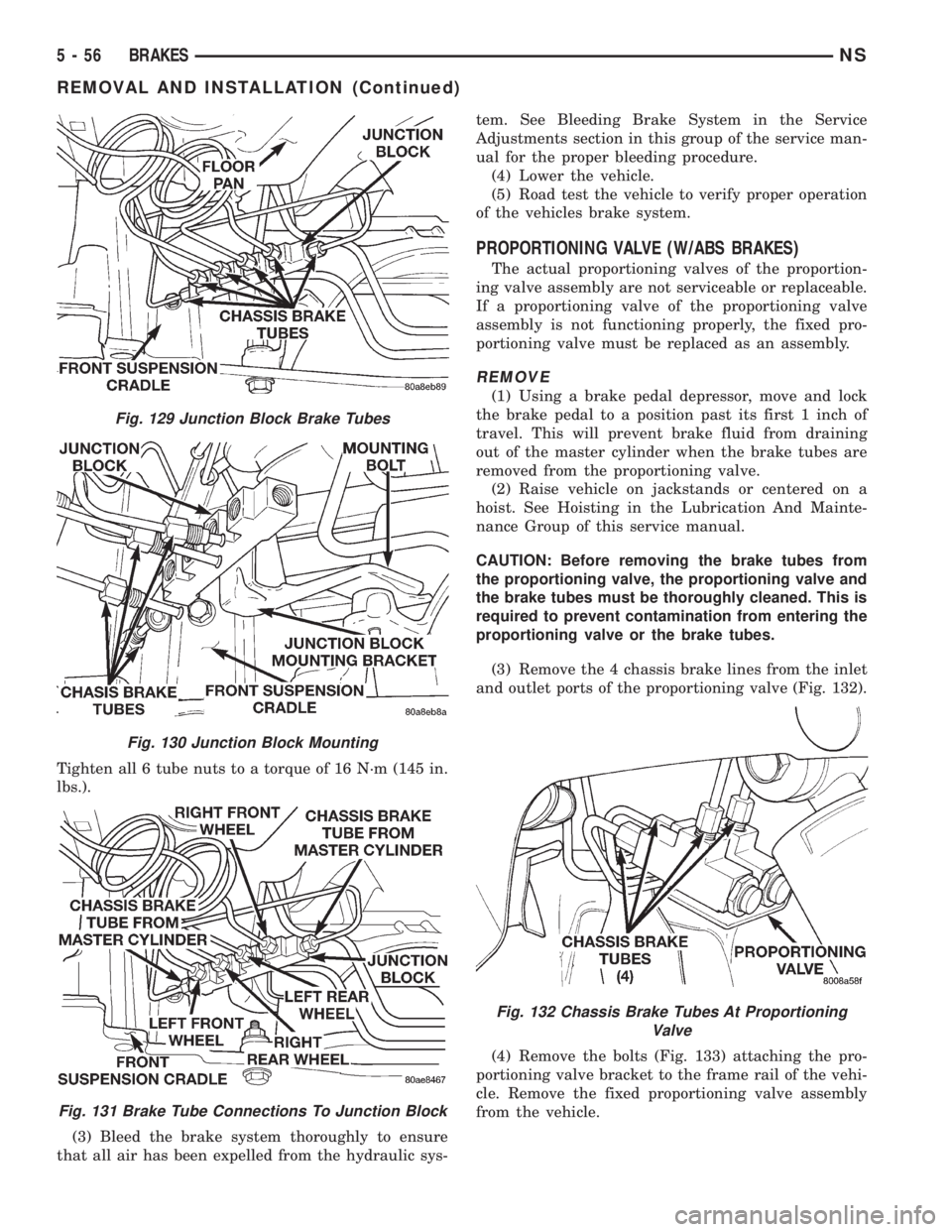
Tighten all 6 tube nuts to a torque of 16 N´m (145 in.
lbs.).
(3) Bleed the brake system thoroughly to ensure
that all air has been expelled from the hydraulic sys-tem. See Bleeding Brake System in the Service
Adjustments section in this group of the service man-
ual for the proper bleeding procedure.
(4) Lower the vehicle.
(5) Road test the vehicle to verify proper operation
of the vehicles brake system.
PROPORTIONING VALVE (W/ABS BRAKES)
The actual proportioning valves of the proportion-
ing valve assembly are not serviceable or replaceable.
If a proportioning valve of the proportioning valve
assembly is not functioning properly, the fixed pro-
portioning valve must be replaced as an assembly.
REMOVE
(1) Using a brake pedal depressor, move and lock
the brake pedal to a position past its first 1 inch of
travel. This will prevent brake fluid from draining
out of the master cylinder when the brake tubes are
removed from the proportioning valve.
(2) Raise vehicle on jackstands or centered on a
hoist. See Hoisting in the Lubrication And Mainte-
nance Group of this service manual.
CAUTION: Before removing the brake tubes from
the proportioning valve, the proportioning valve and
the brake tubes must be thoroughly cleaned. This is
required to prevent contamination from entering the
proportioning valve or the brake tubes.
(3) Remove the 4 chassis brake lines from the inlet
and outlet ports of the proportioning valve (Fig. 132).
(4) Remove the bolts (Fig. 133) attaching the pro-
portioning valve bracket to the frame rail of the vehi-
cle. Remove the fixed proportioning valve assembly
from the vehicle.
Fig. 129 Junction Block Brake Tubes
Fig. 130 Junction Block Mounting
Fig. 131 Brake Tube Connections To Junction Block
Fig. 132 Chassis Brake Tubes At Proportioning
Valve
5 - 56 BRAKESNS
REMOVAL AND INSTALLATION (Continued)
Page 139 of 1938
INSTALL
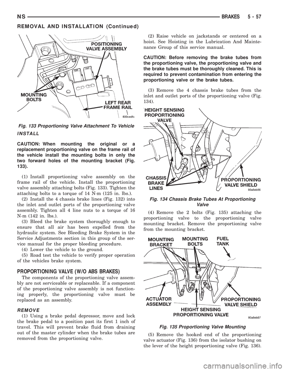
CAUTION: When mounting the original or a
replacement proportioning valve on the frame rail of
the vehicle install the mounting bolts in only the
two forward holes of the mounting bracket (Fig.
133).
(1) Install proportioning valve assembly on the
frame rail of the vehicle. Install the proportioning
valve assembly attaching bolts (Fig. 133). Tighten the
attaching bolts to a torque of 14 N´m (125 in. lbs.).
(2) Install the 4 chassis brake lines (Fig. 132) into
the inlet and outlet ports of the proportioning valve
assembly. Tighten all 4 line nuts to a torque of 16
N´m (142 in. lbs.).
(3) Bleed the brake system thoroughly enough to
ensure that all air has been expelled from the
hydraulic system. See Bleeding Brake System in the
Service Adjustments section in this group of the ser-
vice manual for the proper bleeding procedure.
(4) Lower the vehicle to the ground.
(5) Road test the vehicle to verify proper operation
of the vehicles brake system.
PROPORTIONING VALVE (W/O ABS BRAKES)
The components of the proportioning valve assem-
bly are not serviceable or replaceable. If a component
of the proportioning valve assembly is not function-
ing properly, the proportioning valve must be
replaced as an assembly.
REMOVE
(1) Using a brake pedal depressor, move and lock
the brake pedal to a position past its first 1 inch of
travel. This will prevent brake fluid from draining
out of the master cylinder when the brake tubes are
removed from the proportioning valve.(2) Raise vehicle on jackstands or centered on a
hoist. See Hoisting in the Lubrication And Mainte-
nance Group of this service manual.
CAUTION: Before removing the brake tubes from
the proportioning valve, the proportioning valve and
the brake tubes must be thoroughly cleaned. This is
required to prevent contamination from entering the
proportioning valve or the brake tubes.
(3) Remove the 4 chassis brake tubes from the
inlet and outlet ports of the proportioning valve (Fig.
134).
(4) Remove the 2 bolts (Fig. 135) attaching the
proportioning valve to the proportioning valve
mounting bracket. Remove the proportioning valve
from the mounting bracket.
(5) Remove the hooked end of the proportioning
valve actuator (Fig. 136) from the isolator bushing on
the lever of the height proportioning valve (Fig. 136).
Fig. 133 Proportioning Valve Attachment To Vehicle
Fig. 134 Chassis Brake Tubes At Proportioning
Valve
Fig. 135 Proportioning Valve Mounting
NSBRAKES 5 - 57
REMOVAL AND INSTALLATION (Continued)
Page 140 of 1938
INSTALL
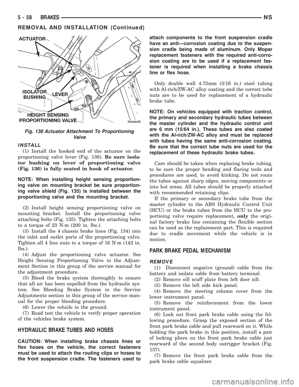
(1) Install the hooked end of the actuator on the
proportioning valve lever (Fig. 136).Be sure isola-
tor bushing on lever of proportioning valve
(Fig. 136) is fully seated in hook of actuator.
NOTE: When installing height sensing proportion-
ing valve on mounting bracket be sure proportion-
ing valve shield (Fig. 135) is installed between the
proportioning valve and the mounting bracket.
(2) Install height sensing proportioning valve on
mounting bracket. Install the proportioning valve
attaching bolts (Fig. 135). Tighten the attaching bolts
to a torque of 23 N´m (200 in. lbs.).
(3) Install the 4 chassis brake lines (Fig. 134) into
the inlet and outlet ports of the proportioning valve.
Tighten all 4 line nuts to a torque of 16 N´m (142 in.
lbs.).
(4) Adjust the proportioning valve actuator. See
Height Sensing Proportioning Valve in the Adjust-
ment Section in this group of the service manual for
the adjustment procedure.
(5) Bleed the brake system thoroughly to ensure
that all air has been expelled from the hydraulic sys-
tem. See Bleeding Brake System in the Service
Adjustments section in this group of the service man-
ual for the proper bleeding procedure.
(6) Lower the vehicle to the ground.
(7) Road test the vehicle to verify proper operation
of the vehicles brake system.
HYDRAULIC BRAKE TUBES AND HOSES
CAUTION: When installing brake chassis lines or
flex hoses on the vehicle, the correct fasteners
must be used to attach the routing clips or hoses to
the front suspension cradle. The fasteners used toattach components to the front suspension cradle
have an antiÐcorrosion coating due to the suspen-
sion cradle being made of aluminum. Only Mopar
replacement fasteners with the required anti-corro-
sion coating are to be used if a replacement fas-
tener is required when installing a brake chassis
line or flex hose.
Only double wall 4.75mm (3/16 in.) steel tubing
with Al-rich/ZW-AC alloy coating and the correct tube
nuts are to be used for replacement of a hydraulic
brake tube.
NOTE: On vehicles equipped with traction control,
the primary and secondary hydraulic tubes between
the master cylinder and the hydraulic control unit
are 6 mm (15/64 in.). These tubes are also coated
with the Al-rich/ZW-AC alloy and must be replaced
with tubes having the same anti-corrosion coating.
Be sure that the correct tube nuts are used for the
replacement of these hydraulic brake tubes.
Care should be taken when replacing brake tubing,
to be sure the proper bending and flaring tools and
procedures are used, to avoid kinking. Do not route
the tubes against sharp edges, moving components or
into hot areas. All tubes should be properly attached
with recommended retaining clips.
If the primary or secondary brake tube from the
master cylinder to the ABS Hydraulic Control Unit
(HCU) or the brake tubes from the HCU to the pro-
portioing valve require replacement,onlythe origi-
nal factory brake line containing the flexible section
can be used as the replacement part. This is required
due to cradle movement while the vehicle is in
motion.
PARK BRAKE PEDAL MECHANISM
REMOVE
(1) Disconnect negative (ground) cable from the
battery and isolate cable from battery terminal.
(2) Remove sill scuff plate from left door sill.
(3) Remove the left side kick panel.
(4) Remove the steering column cover from the
lower instrument panel.
(5) Remove the reinforcement from the lower
instrument panel.
(6) Lock out front park brake cable using the fol-
lowing procedure. Grasp the exposed section of the
front park brake cable and pull rearward on it. While
holding the park brake in this position, install a pair
of locking pliers on the front park brake cable just
rearward of the second body outrigger bracket (Fig.
137).
(7) Remove the front park brake cable from the
park brake cable equalizer.
Fig. 136 Actuator Attachment To Proportioning
Valve
5 - 58 BRAKESNS
REMOVAL AND INSTALLATION (Continued)