check engine CHRYSLER VOYAGER 1996 Service Manual
[x] Cancel search | Manufacturer: CHRYSLER, Model Year: 1996, Model line: VOYAGER, Model: CHRYSLER VOYAGER 1996Pages: 1938, PDF Size: 55.84 MB
Page 1256 of 1938
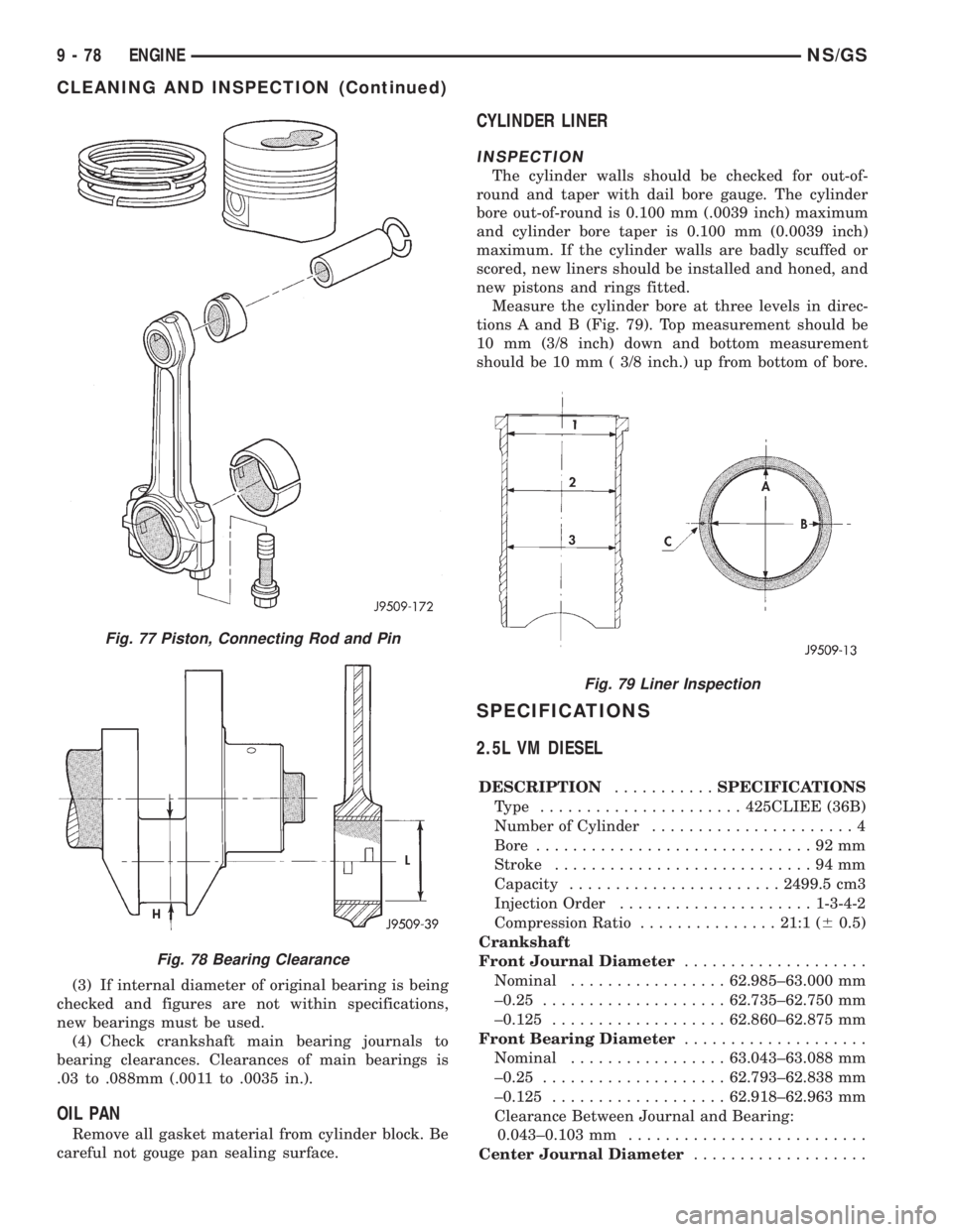
(3) If internal diameter of original bearing is being
checked and figures are not within specifications,
new bearings must be used.
(4) Check crankshaft main bearing journals to
bearing clearances. Clearances of main bearings is
.03 to .088mm (.0011 to .0035 in.).
OIL PAN
Remove all gasket material from cylinder block. Be
careful not gouge pan sealing surface.
CYLINDER LINER
INSPECTION
The cylinder walls should be checked for out-of-
round and taper with dail bore gauge. The cylinder
bore out-of-round is 0.100 mm (.0039 inch) maximum
and cylinder bore taper is 0.100 mm (0.0039 inch)
maximum. If the cylinder walls are badly scuffed or
scored, new liners should be installed and honed, and
new pistons and rings fitted.
Measure the cylinder bore at three levels in direc-
tions A and B (Fig. 79). Top measurement should be
10 mm (3/8 inch) down and bottom measurement
should be 10 mm ( 3/8 inch.) up from bottom of bore.
SPECIFICATIONS
2.5L VM DIESEL
DESCRIPTION...........SPECIFICATIONS
Type ......................425CLIEE (36B)
Number of Cylinder......................4
Bore..............................92mm
Stroke............................94mm
Capacity.......................2499.5 cm3
Injection Order.....................1-3-4-2
Compression Ratio...............21:1 (60.5)
Crankshaft
Front Journal Diameter....................
Nominal.................62.985±63.000 mm
±0.25....................62.735±62.750 mm
±0.125...................62.860±62.875 mm
Front Bearing Diameter....................
Nominal.................63.043±63.088 mm
±0.25....................62.793±62.838 mm
±0.125...................62.918±62.963 mm
Clearance Between Journal and Bearing:
0.043±0.103 mm..........................
Center Journal Diameter...................
Fig. 77 Piston, Connecting Rod and Pin
Fig. 78 Bearing Clearance
Fig. 79 Liner Inspection
9 - 78 ENGINENS/GS
CLEANING AND INSPECTION (Continued)
Page 1265 of 1938
CAUTION: When servicing, care must be exercised
not to dent or bend the bellows of the flex-joint.
Should this occur, the flex-joint will eventually fail
and require the catalytic converter be replaced.
DESCRIPTION AND OPERATION
INTAKE/EXHAUST MANIFOLDÐ2.4L ENGINE
The intake manifold is a tuned two-piece alumi-
num casting with individual primary runners leading
from a plenum to the cylinders. The manifold is
designed to boost torque which is desired for excel-
lent engine response and usable power output.
The exhaust manifold is made of nodular cast iron
for strength and high temperatures.
INTAKE/EXHAUST MANIFOLDÐ3.0L ENGINE
The aluminum alloy manifold is a cross type with
long runners to improve air flow. The runners,
attaching below at the cylinder head, also attach
above and support an air plenum. The air plenum
chamber absorbs air pulsations created during the
suction phase of each cylinder.Both exhaust manifolds are a log style made of
ductile cast iron. Exhaust gasses, collected from the
front cylinder bank, leave the front manifold through
an end outlet and are fed through an upper crossover
tube to the rear manifold. The collected exhaust from
both manifolds are combined at the exhaust outlet, to
the exhaust pipe.
INTAKE/EXHAUST MANIFOLDÐ3.3/3.8L ENGINES
The intake manifold is a tuned two-piece semi-per-
manent mold aluminum casting with individual pri-
mary runners leading from a plenum to the
cylinders. The manifold is designed to boost torque in
the 3600 rpm range and contributes to the engine's
broad, flat torque curve, which was desired for excel-
lent engine tractability, response and usable power
output.
The intake manifold is also cored with upper level
EGR passages for balanced cylinder to cylinder EGR
distribution.
The exhaust manifolds are log type with a cross-
over and are attached directly to the cylinder heads.
They are made from nodular cast iron.
DIAGNOSIS AND TESTING
EXHAUST SYSTEM
CONDITION POSSIBLE CAUSES CORRECTION
EXCESSIVE EXHAUST
NOISE (UNDER HOOD)1. Exhaust manifold cracked or broken. 1. Replace manifold.
2. Manifold to cylinder head leak. 2. Tighten manifold and/or replace gasket.
3. EGR Valve to manifold gasket leakage. 3. Tighten fasteners or replace gasket.
4. EGR Valve to EGR tube gasket
leakage.4. Tighten fasteners or replace gasket.
5. EGR tube to manifold tube leakage. 5. Tighten tube nut.
6. Exhaust flex-joint to manifold leak. 6. Tighten joint fasteners and/or replace
gasket.
7. Exhaust flex-joint. 7. Replace catalytic converter assembly.
8. Pipe and shell noise from front exhaust
pipe.8. Characteristic of single wall pipe.
EXCESSIVE EXHAUST
NOISE1. Leak at exhaust pipe joints. 1. Tighten clamps at leaking joints.
2. Burned or rusted out muffler assembly
or exhaust pipe.2. Replace muffler resonator tailpipe
assembly or exhaust pipe with catalytic
converter assembly.
3. Burned or rusted out resonator. 3. Replace muffler resonator tailpipe
assembly.
4. Restriction in exhaust system. 4. Remove restriction, if possible, or
replace as necessary.
5. Converter material in muffler. 5. Replace muffler and converter
assemblies. Check fuel injection and
ignition systems for proper operation.
NSEXHAUST SYSTEM AND INTAKE MANIFOLD 11 - 3
GENERAL INFORMATION (Continued)
Page 1270 of 1938
(2) Tighten intake manifold fasteners in the fol-
lowing sequence (Fig. 16). Torque to 23 N´m (200 in.
lbs.). Repeat this procedure until all bolts are at
specified torque.
(3) Install intake manifold center support bracket
bolts (Y bracket):
²Fastener to block 54 N´m (40 ft. lbs.)
²Fastener to intake 28 N´m (250 in. lbs.)
(4) Install fuel hose quick connector fitting to
chassis tubes.Refer to Fuel Hoses, Clamps and
Quick Connect Fittings in Group 14, Fuel Deliv-
ery.Push the fitting onto the chassis tube until it
clicks into place. Pull on the fitting to ensure com-
plete insertion.
(5) Reverse removal procedures 2 through 12 for
installation.
CAUTION: When using the ASD Fuel System Test,
the ASD relay and fuel pump relay remain energized
for 7 minutes or until the test is stopped, or until
the ignition switch is turned to the Off position.
(6) With the ignition key in ON position, access
the DRB scan tool ASD Fuel System Test to pressur-
ize the fuel system. Check for leaks.
EXHAUST MANIFOLDÐ2.4L ENGINE
REMOVAL
(1) Raise vehicle and disconnect exhaust pipe from
the exhaust manifold at the flex-joint.
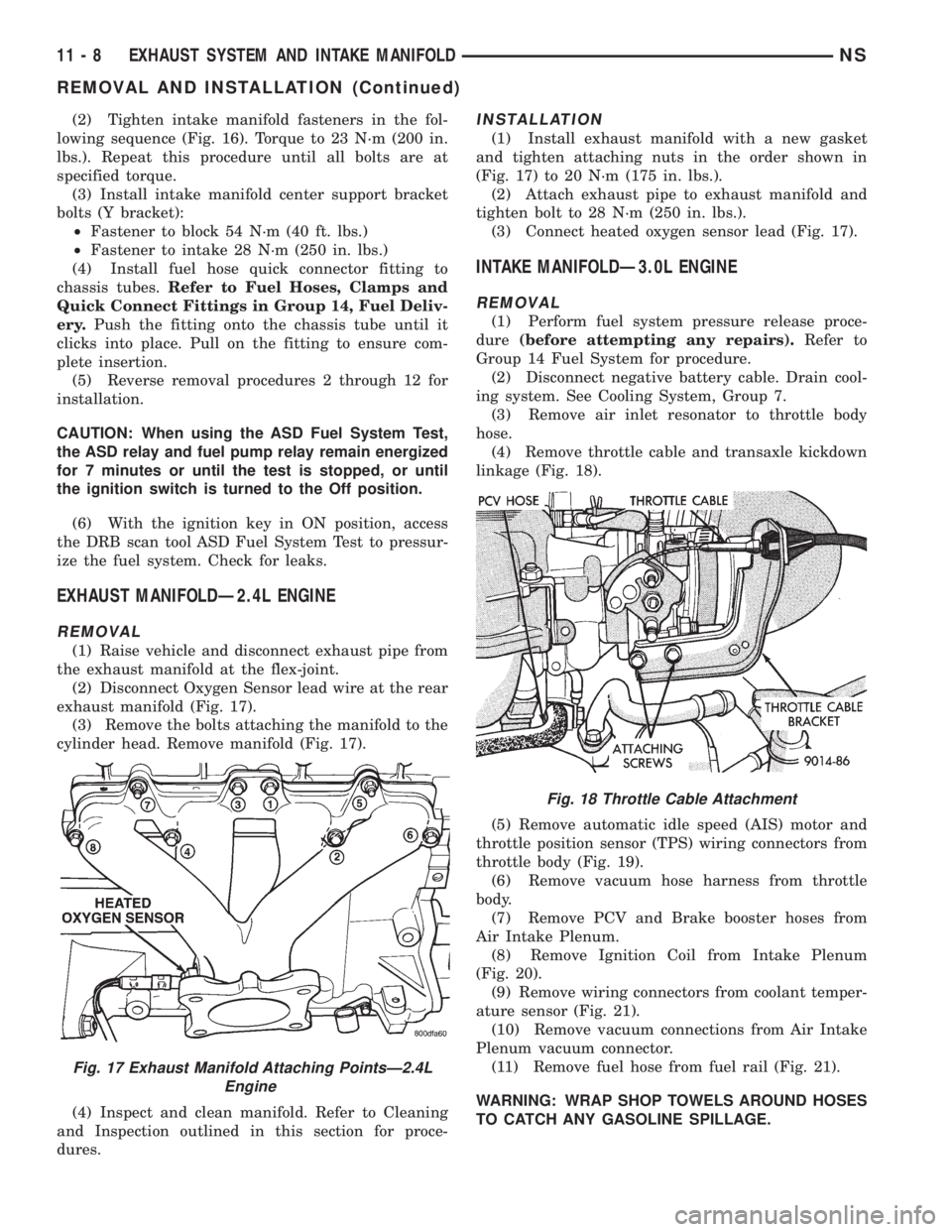
(2) Disconnect Oxygen Sensor lead wire at the rear
exhaust manifold (Fig. 17).
(3) Remove the bolts attaching the manifold to the
cylinder head. Remove manifold (Fig. 17).
(4) Inspect and clean manifold. Refer to Cleaning
and Inspection outlined in this section for proce-
dures.
INSTALLATION
(1) Install exhaust manifold with a new gasket
and tighten attaching nuts in the order shown in
(Fig. 17) to 20 N´m (175 in. lbs.).
(2) Attach exhaust pipe to exhaust manifold and
tighten bolt to 28 N´m (250 in. lbs.).
(3) Connect heated oxygen sensor lead (Fig. 17).
INTAKE MANIFOLDÐ3.0L ENGINE
REMOVAL
(1) Perform fuel system pressure release proce-
dure(before attempting any repairs).Refer to
Group 14 Fuel System for procedure.
(2) Disconnect negative battery cable. Drain cool-
ing system. See Cooling System, Group 7.
(3) Remove air inlet resonator to throttle body
hose.
(4) Remove throttle cable and transaxle kickdown
linkage (Fig. 18).
(5) Remove automatic idle speed (AIS) motor and
throttle position sensor (TPS) wiring connectors from
throttle body (Fig. 19).
(6) Remove vacuum hose harness from throttle
body.
(7) Remove PCV and Brake booster hoses from
Air Intake Plenum.
(8) Remove Ignition Coil from Intake Plenum
(Fig. 20).
(9) Remove wiring connectors from coolant temper-
ature sensor (Fig. 21).
(10) Remove vacuum connections from Air Intake
Plenum vacuum connector.
(11) Remove fuel hose from fuel rail (Fig. 21).
WARNING: WRAP SHOP TOWELS AROUND HOSES
TO CATCH ANY GASOLINE SPILLAGE.
Fig. 17 Exhaust Manifold Attaching PointsÐ2.4L
Engine
Fig. 18 Throttle Cable Attachment
11 - 8 EXHAUST SYSTEM AND INTAKE MANIFOLDNS
REMOVAL AND INSTALLATION (Continued)
Page 1273 of 1938
(10) Connect fuel line to fuel rail (Fig. 21). Torque
hose clamps to 1 N´m (10 in. lbs.).
(11) Connect vacuum harness to air intake ple-
num.
(12) Connect and coolant temperature sensor elec-
trical connector to sensor (Fig. 21).
(13) Connect PCV and brake booster supply hose
to intake plenum.
(14) Connect automatic idle speed (AIS) motor
and throttle position sensor (TPS) electrical connec-
tors (Fig. 19).
(15) Connect vacuum vapor harness to throttle
body (Fig. 19).
(16) Install throttle cable and transaxle kickdown
linkage (Fig. 18).
(17) Install air inlet resonator hose assembly to
throttle body.
(18) Install radiator to thermostat housing hose
and heater hose to heater pipe nipple.
(19) Fill cooling system. Refer to Filling the Cool-
ing System outlined in Group 7 Cooling System for
procedure.
(20) Connect negative battery cable.
(21) With the DRB Scan Tool use ASD Fuel Sys-
tem Test to pressurize system to check for leaks.
CAUTION: When using the ASD Fuel System Test,
The Auto Shutdown (ASD) Relay will remain ener-
gized for 7 minutes or until the ignition switch is
turned to the OFF position, or Stop All Test is
selected.
EXHAUST MANIFOLDÐ3.0L ENGINE
REMOVAL
(1) Raise vehicle and disconnect exhaust pipe
from rear (cowl side) exhaust manifold at the flex-
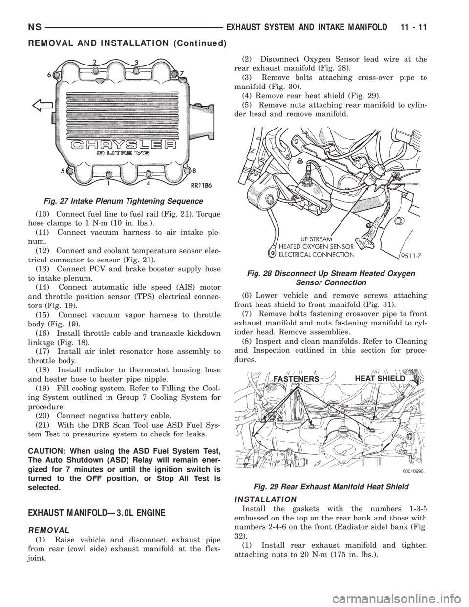
joint.(2) Disconnect Oxygen Sensor lead wire at the
rear exhaust manifold (Fig. 28).
(3) Remove bolts attaching cross-over pipe to
manifold (Fig. 30).
(4) Remove rear heat shield (Fig. 29).
(5) Remove nuts attaching rear manifold to cylin-
der head and remove manifold.
(6) Lower vehicle and remove screws attaching
front heat shield to front manifold (Fig. 31).
(7) Remove bolts fastening crossover pipe to front
exhaust manifold and nuts fastening manifold to cyl-
inder head. Remove assemblies.
(8) Inspect and clean manifolds. Refer to Cleaning
and Inspection outlined in this section for proce-
dures.
INSTALLATION
Install the gaskets with the numbers 1-3-5
embossed on the top on the rear bank and those with
numbers 2-4-6 on the front (Radiator side) bank (Fig.
32).
(1) Install rear exhaust manifold and tighten
attaching nuts to 20 N´m (175 in. lbs.).
Fig. 27 Intake Plenum Tightening Sequence
Fig. 28 Disconnect Up Stream Heated Oxygen
Sensor Connection
Fig. 29 Rear Exhaust Manifold Heat Shield
NSEXHAUST SYSTEM AND INTAKE MANIFOLD 11 - 11
REMOVAL AND INSTALLATION (Continued)
Page 1277 of 1938
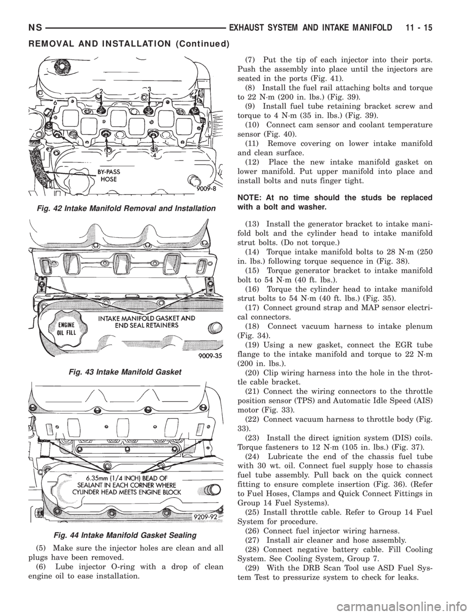
(5) Make sure the injector holes are clean and all
plugs have been removed.
(6) Lube injector O-ring with a drop of clean
engine oil to ease installation.(7) Put the tip of each injector into their ports.
Push the assembly into place until the injectors are
seated in the ports (Fig. 41).
(8) Install the fuel rail attaching bolts and torque
to 22 N´m (200 in. lbs.) (Fig. 39).
(9) Install fuel tube retaining bracket screw and
torque to 4 N´m (35 in. lbs.) (Fig. 39).
(10) Connect cam sensor and coolant temperature
sensor (Fig. 40).
(11) Remove covering on lower intake manifold
and clean surface.
(12) Place the new intake manifold gasket on
lower manifold. Put upper manifold into place and
install bolts and nuts finger tight.
NOTE: At no time should the studs be replaced
with a bolt and washer.
(13) Install the generator bracket to intake mani-
fold bolt and the cylinder head to intake manifold
strut bolts. (Do not torque.)
(14) Torque intake manifold bolts to 28 N´m (250
in. lbs.) following torque sequence in (Fig. 38).
(15) Torque generator bracket to intake manifold
bolt to 54 N´m (40 ft. lbs.).
(16) Torque the cylinder head to intake manifold
strut bolts to 54 N´m (40 ft. lbs.) (Fig. 35).
(17) Connect ground strap and MAP sensor electri-
cal connectors.
(18) Connect vacuum harness to intake plenum
(Fig. 34).
(19) Using a new gasket, connect the EGR tube
flange to the intake manifold and torque to 22 N´m
(200 in. lbs.).
(20) Clip wiring harness into the hole in the throt-
tle cable bracket.
(21) Connect the wiring connectors to the throttle
position sensor (TPS) and Automatic Idle Speed (AIS)
motor (Fig. 33).
(22) Connect vacuum harness to throttle body (Fig.
33).
(23) Install the direct ignition system (DIS) coils.
Torque fasteners to 12 N´m (105 in. lbs.) (Fig. 37).
(24) Lubricate the end of the chassis fuel tube
with 30 wt. oil. Connect fuel supply hose to chassis
fuel tube assembly. Pull back on the quick connect
fitting to ensure complete insertion (Fig. 36). (Refer
to Fuel Hoses, Clamps and Quick Connect Fittings in
Group 14 Fuel Systems).
(25) Install throttle cable. Refer to Group 14 Fuel
System for procedure.
(26) Connect fuel injector wiring harness.
(27) Install air cleaner and hose assembly.
(28) Connect negative battery cable. Fill Cooling
System. See Cooling System, Group 7.
(29) With the DRB Scan Tool use ASD Fuel Sys-
tem Test to pressurize system to check for leaks.
Fig. 42 Intake Manifold Removal and Installation
Fig. 43 Intake Manifold Gasket
Fig. 44 Intake Manifold Gasket Sealing
NSEXHAUST SYSTEM AND INTAKE MANIFOLD 11 - 15
REMOVAL AND INSTALLATION (Continued)
Page 1298 of 1938
FUEL DELIVERY SYSTEM
INDEX
page page
DESCRIPTION AND OPERATION
FUEL DELIVERY SYSTEM.................. 4
FUEL INJECTORS........................ 5
FUEL LEVEL SENSOR..................... 5
FUEL PRESSURE REGULATOR.............. 5
FUEL PUMP MODULE..................... 4
FUEL TANK............................. 5
PRESSURE-VACUUM FILLER CAP........... 6
QUICK-CONNECT FITTINGS................ 6
DIAGNOSIS AND TESTING
FUEL INJECTORS........................ 9
FUEL LEVEL SENSOR..................... 9
FUEL PUMP PRESSURE TEST 2.4/3.3/3.8L..... 6
SERVICE PROCEDURES
FUEL SYSTEM PRESSURE RELEASE
PROCEDUREÐ2.4/3.3/3.8L............... 11
FUEL SYSTEM PRESSURE RELEASE
PROCEDUREÐ3.0L ENGINE............. 11
HOSES AND CLAMPS.................... 12QUICK-CONNECT FITTINGS............... 12
REMOVAL AND INSTALLATION
ACCELERATOR PEDAL................... 26
FUEL FILTER........................... 12
FUEL INJECTOR RAILÐ2.4L............... 18
FUEL INJECTOR RAILÐ3.0L............... 19
FUEL INJECTOR RAILÐ3.3/3.8L............ 21
FUEL INJECTORSÐ3.0L.................. 25
FUEL INJECTORÐ2.4L................... 24
FUEL INJECTORÐ3.3/3.8L................. 26
FUEL LEVEL SENSOR.................... 15
FUEL PRESSURE REGULATOR............. 14
FUEL PUMP INLET STRAINER............. 15
FUEL PUMP MODULE.................... 13
FUEL TANK............................ 17
THROTTLE CABLE...................... 27
SPECIFICATIONS
FUEL TANK CAPACITY................... 28
TORQUE.............................. 28
DESCRIPTION AND OPERATION
FUEL DELIVERY SYSTEM
The front wheel drive van uses a plastic fuel tank
located on the left side of the vehicle.
The Fuel Delivery System consists of: the electric
fuel pump module, fuel filter, tubes/lines/hoses, fuel
rail, and fuel injectors.
The in-tank fuel pump module contains the fuel
pump and pressure regulator. The pump is serviced
as part of the fuel pump module. Refer to Fuel Pump
Module.
The fuel filter is a replaceable in-line filter. The fil-
ter attaches to a bracket mounted on top of the fuel
tank. Refer to the Maintenance Schedules in the
Introduction section of this manual for recommended
fuel filter replacement intervals.
A returnless fuel system is used on all vehicles.
Fuel is returned through the fuel pump module and
back to the fuel tank. A separate fuel return line
from the tank to the engine is no longer used.
FUEL PUMP MODULE
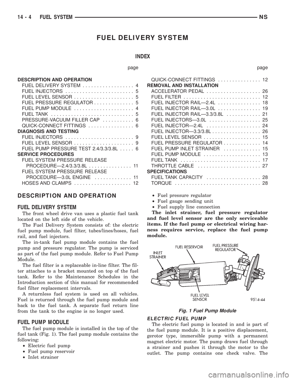
The fuel pump module is installed in the top of the
fuel tank (Fig. 1). The fuel pump module contains the
following:
²Electric fuel pump
²Fuel pump reservoir
²Inlet strainer²Fuel pressure regulator
²Fuel gauge sending unit
²Fuel supply line connection
The inlet strainer, fuel pressure regulator
and fuel level sensor are the only serviceable
items. If the fuel pump or electrical wiring har-
ness requires service, replace the fuel pump
module.
ELECTRIC FUEL PUMP
The electric fuel pump is located in and is part of
the fuel pump module. It is a positive displacement,
gerotor type, immersible pump with a permanent
magnet electric motor. The pump draws fuel through
a strainer and pushes it through the motor to the
outlet. The pump contains one check valve. The
Fig. 1 Fuel Pump Module
14 - 4 FUEL SYSTEMNS
Page 1299 of 1938
check valve, in the pump outlet, maintains pump
pressure during engine off conditions. The fuel pump
relay provides voltage to the fuel pump.
The fuel pump has a maximum deadheaded pres-
sure output of approximately 635 kPa (95 psi). The
regulator adjusts fuel system pressure to approxi-
mately 338 kPa (49 psi).
FUEL PUMP ELECTRICAL CONTROL
Voltage to operate the electric pump is supplied
through the fuel pump relay. For an electrical opera-
tional description of the fuel pump refer to fuel Pump
RelayÐPCM Output.
ELECTRICAL PUMP REPLACEMENT
The electric fuel pump is not serviceable. If the
fuel pump or electrical wiring harness needs replace-
ment, the complete fuel pump module must be
replaced. Perform the Fuel System Pressure Release
procedure before servicing the fuel pump.
FUEL LEVEL SENSOR
The level sensor is attached to the side of the fuel
pump module. The level sensor consists of a float, an
arm, and a variable resistor. As the fuel level
increases, the float and arm move up. This decreases
the sending unit resistance, causing the fuel gauge
on the instrument panel to read full.
FUEL PRESSURE REGULATOR
The fuel system uses a nonadjustable pressure reg-
ulator that maintains fuel system pressure at
approximately 338 kPa (49 psi), 3.3l uses approxi-
mately 379 kPa (55 psi). The fuel pressure regulator
contains a diaphragm, calibrated spring and a fuel
return valve. The spring pushes down on the dia-
phragm and closes off the fuel return port. System
fuel pressure reflects the amount of fuel pressure
required to open the return port.
The pressure regulator is a mechanical device that
is NOT controlled by the PCM or engine vacuum.
FUEL INJECTORS
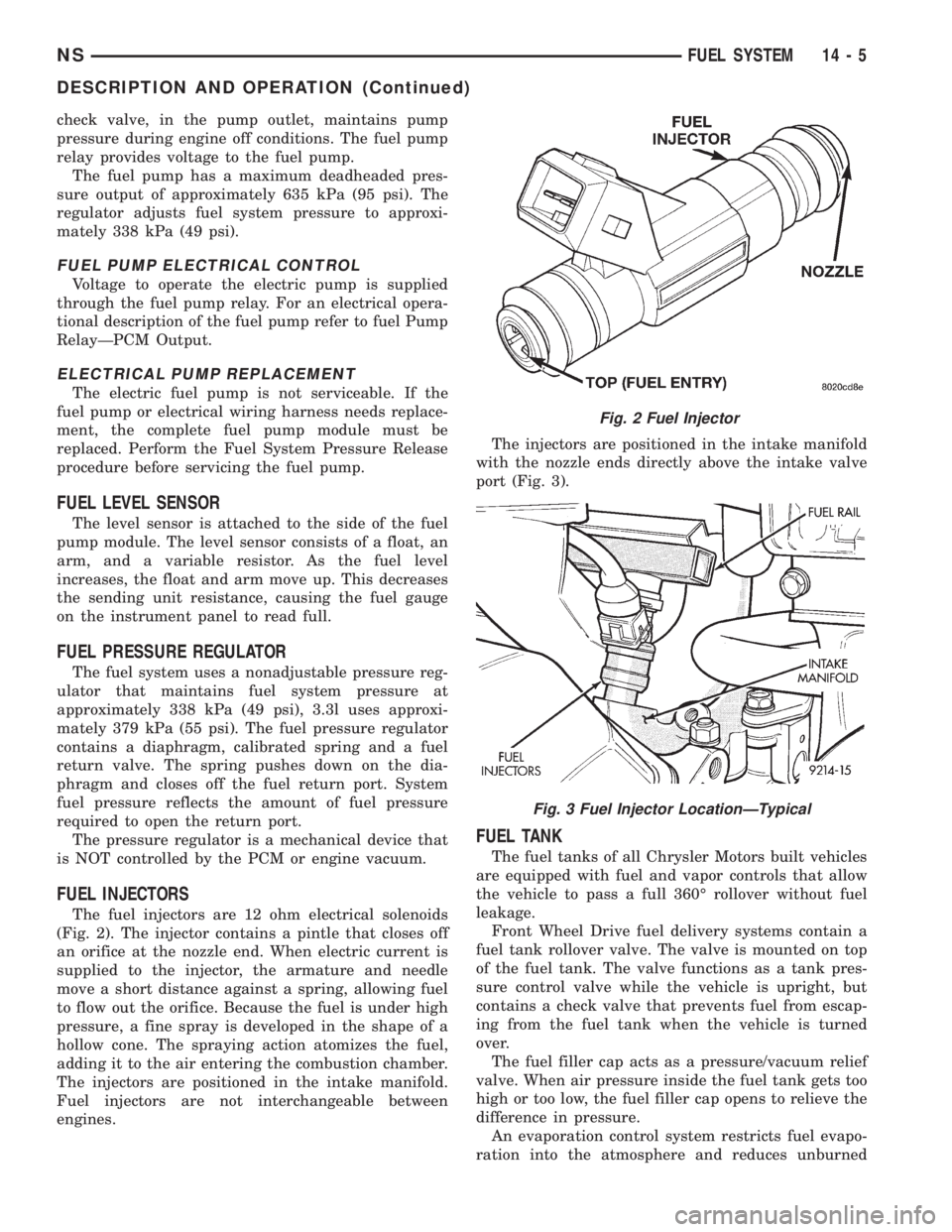
The fuel injectors are 12 ohm electrical solenoids
(Fig. 2). The injector contains a pintle that closes off
an orifice at the nozzle end. When electric current is
supplied to the injector, the armature and needle
move a short distance against a spring, allowing fuel
to flow out the orifice. Because the fuel is under high
pressure, a fine spray is developed in the shape of a
hollow cone. The spraying action atomizes the fuel,
adding it to the air entering the combustion chamber.
The injectors are positioned in the intake manifold.
Fuel injectors are not interchangeable between
engines.The injectors are positioned in the intake manifold
with the nozzle ends directly above the intake valve
port (Fig. 3).
FUEL TANK
The fuel tanks of all Chrysler Motors built vehicles
are equipped with fuel and vapor controls that allow
the vehicle to pass a full 360É rollover without fuel
leakage.
Front Wheel Drive fuel delivery systems contain a
fuel tank rollover valve. The valve is mounted on top
of the fuel tank. The valve functions as a tank pres-
sure control valve while the vehicle is upright, but
contains a check valve that prevents fuel from escap-
ing from the fuel tank when the vehicle is turned
over.
The fuel filler cap acts as a pressure/vacuum relief
valve. When air pressure inside the fuel tank gets too
high or too low, the fuel filler cap opens to relieve the
difference in pressure.
An evaporation control system restricts fuel evapo-
ration into the atmosphere and reduces unburned
Fig. 2 Fuel Injector
Fig. 3 Fuel Injector LocationÐTypical
NSFUEL SYSTEM 14 - 5
DESCRIPTION AND OPERATION (Continued)
Page 1300 of 1938
hydrocarbons. Vapors from the fuel tank are collected
in a charcoal filled canister. The vapors are held in
the canister until the engine is operating. When the
engine is running, the vapors are drawn through the
intake manifold into the combustion chambers.
PRESSURE-VACUUM FILLER CAP
The loss of any fuel or vapor out of the filler neck
is prevented by the use of a safety filler cap. The cap
will release pressure only under significant pressure
of 10.9 to 13.45 kPa (1.58 to 1.95 psi). The vacuum
release for all gas caps is between 0.97 and 2.0 kPa
(0.14 and 0.29 psi). The cap must be replaced by a
similar unit if replacement is necessary.
WARNING: REMOVE FILLER CAP TO RELIEVE
TANK PRESSURE BEFORE REMOVING OR REPAIR-
ING FUEL SYSTEM COMPONENTS.
QUICK-CONNECT FITTINGS
Different types of quick-connect fittings are used to
attach various fuel system components. These are: a
single-tab type, a two-tab type or a plastic retainer
ring type. Some are equipped with safety latch clips.
Refer to the Removal/Installation section for more
information.
CAUTION: The interior components (o-rings, spac-
ers) of quick-connect fitting are not serviced sepa-
rately. Do not attempt to repair damaged fittings or
fuel lines/tubes. If repair is necessary, replace the
complete fuel tube assembly.
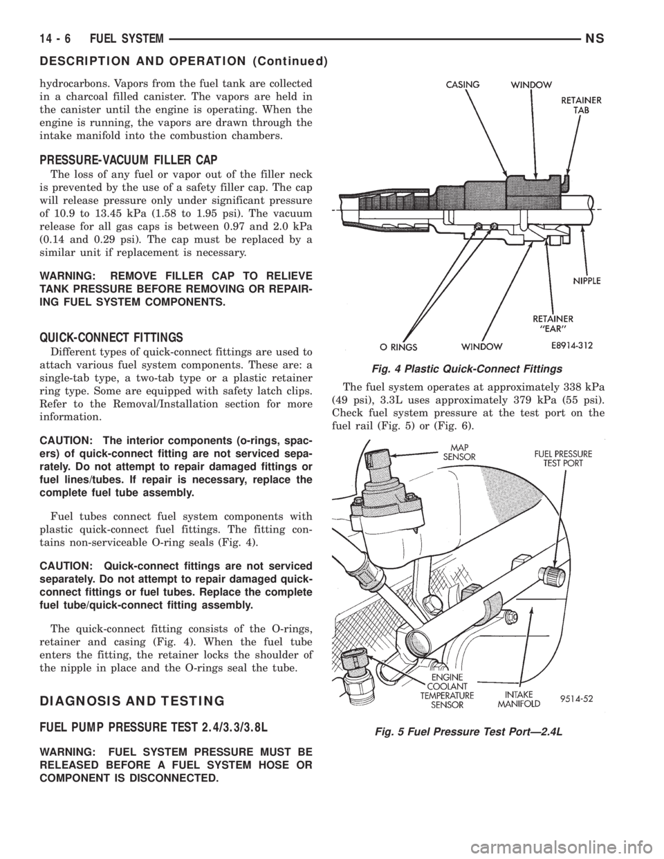
Fuel tubes connect fuel system components with
plastic quick-connect fuel fittings. The fitting con-
tains non-serviceable O-ring seals (Fig. 4).
CAUTION: Quick-connect fittings are not serviced
separately. Do not attempt to repair damaged quick-
connect fittings or fuel tubes. Replace the complete
fuel tube/quick-connect fitting assembly.
The quick-connect fitting consists of the O-rings,
retainer and casing (Fig. 4). When the fuel tube
enters the fitting, the retainer locks the shoulder of
the nipple in place and the O-rings seal the tube.
DIAGNOSIS AND TESTING
FUEL PUMP PRESSURE TEST 2.4/3.3/3.8L
WARNING: FUEL SYSTEM PRESSURE MUST BE
RELEASED BEFORE A FUEL SYSTEM HOSE OR
COMPONENT IS DISCONNECTED.The fuel system operates at approximately 338 kPa
(49 psi), 3.3L uses approximately 379 kPa (55 psi).
Check fuel system pressure at the test port on the
fuel rail (Fig. 5) or (Fig. 6).
Fig. 4 Plastic Quick-Connect Fittings
Fig. 5 Fuel Pressure Test PortÐ2.4L
14 - 6 FUEL SYSTEMNS
DESCRIPTION AND OPERATION (Continued)
Page 1306 of 1938
(9) Momentarily touch the other end of this
jumper wire to the negative terminal of the battery
for no more than 4 seconds.
(10) Place a rag or towel below the fuel line at the
quick connect to the rail.
(11) Disconnect the quick connect fitting to the
rail. Refer to Quick-Connect Fittings in this section.
(12) Return the fuel pump relay to the PDC.
(13) One or more Diagnostic Trouble Codes (DTC's)
may have been stored in the PCM memory due to the
fuel pump relay removal. The DRB scan tool must be
used to erase a DTC. Refer to group 25, On-Board
Diagnostics.
HOSES AND CLAMPS
Inspect all hose connections (clamps and quick con-
nect fittings) for completeness and leaks. Replace
cracked, scuffed, or swelled hoses. Replace hoses that
rub against other vehicle components or show sign of
wear.
Fuel injected vehicles use specially constructed
hoses. When replacing hoses, only use hoses marked
EFM/EFI.
When installing hoses, ensure that they are routed
away from contact with other vehicle components
that could rub against them and cause failure. Avoid
contact with clamps or other components that cause
abrasions or scuffing. Ensure that rubber hoses are
properly routed and avoid heat sources.
The hose clamps have rolled edges to prevent the
clamp from cutting into the hose. Only use clamps
that are original equipment or equivalent. Other
types of clamps may cut into the hoses and cause
high pressure fuel leaks. Tighten hose clamps to 1
N´m (10 in. lbs.) torque.
QUICK-CONNECT FITTINGS
REMOVAL
When disconnecting a quick-connect fitting, the
retainer will remain on the fuel tube nipple.
WARNING: RELEASE FUEL SYSTEM PRESSURE
BEFORE DISCONNECTING A QUICK-CONNECT FIT-
TINGS. REFER TO THE FUEL PRESSURE RELEASE
PROCEDURE.
(1) Disconnect negative cable from battery.
(2) Perform Fuel Pressure Release Procedure.
Refer to the Fuel Pressure Release Procedure in this
section.
(3) Squeeze retainer tabs together and pull fuel
tube/quick-connect fitting assembly off of fuel tube
nipple. The retainer will remain on fuel tube.
INSTALLATION
CAUTION: Never install a quick-connect fitting
without the retainer being either on the fuel tube or
already in the quick-connect fitting. In either case,
ensure the retainer locks securely into the quick-
connect fitting by firmly pulling on fuel tube and fit-
ting to ensure it is secured.
(1) Using a clean lint free cloth, clean the fuel tube
nipple and retainer.
(2) Prior to connecting the fitting to the fuel tube,
coat the fuel tube nipple with clean 30 weight engine
oil.
(3) Push the quick-connect fitting over the fuel
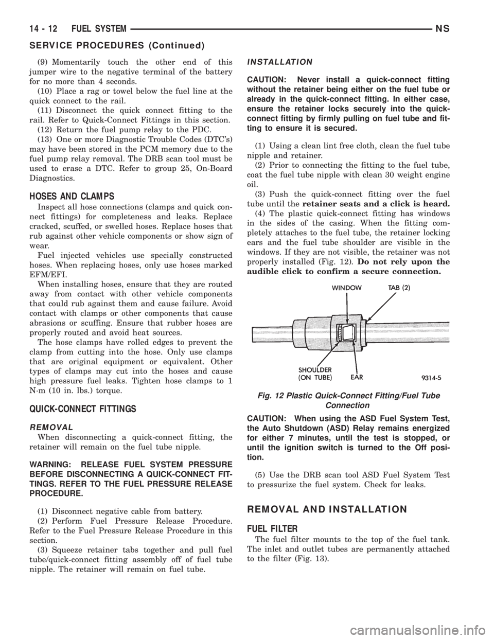
tube until theretainer seats and a click is heard.
(4) The plastic quick-connect fitting has windows
in the sides of the casing. When the fitting com-
pletely attaches to the fuel tube, the retainer locking
ears and the fuel tube shoulder are visible in the
windows. If they are not visible, the retainer was not
properly installed (Fig. 12).Do not rely upon the
audible click to confirm a secure connection.
CAUTION: When using the ASD Fuel System Test,
the Auto Shutdown (ASD) Relay remains energized
for either 7 minutes, until the test is stopped, or
until the ignition switch is turned to the Off posi-
tion.
(5) Use the DRB scan tool ASD Fuel System Test
to pressurize the fuel system. Check for leaks.
REMOVAL AND INSTALLATION
FUEL FILTER
The fuel filter mounts to the top of the fuel tank.
The inlet and outlet tubes are permanently attached
to the filter (Fig. 13).
Fig. 12 Plastic Quick-Connect Fitting/Fuel Tube
Connection
14 - 12 FUEL SYSTEMNS
SERVICE PROCEDURES (Continued)
Page 1308 of 1938
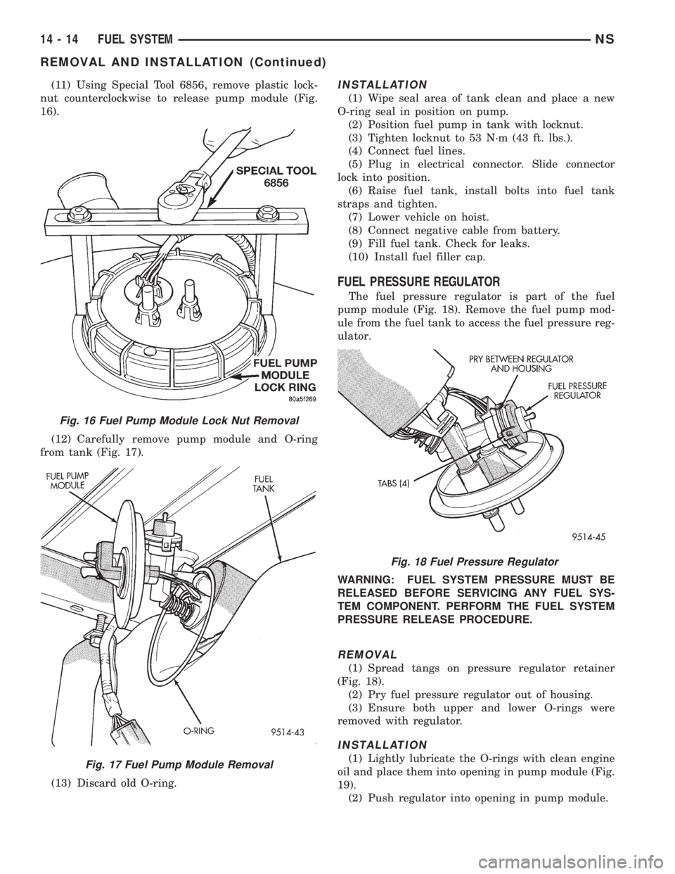
(11) Using Special Tool 6856, remove plastic lock-
nut counterclockwise to release pump module (Fig.
16).
(12) Carefully remove pump module and O-ring
from tank (Fig. 17).
(13) Discard old O-ring.INSTALLATION
(1) Wipe seal area of tank clean and place a new
O-ring seal in position on pump.
(2) Position fuel pump in tank with locknut.
(3) Tighten locknut to 53 N´m (43 ft. lbs.).
(4) Connect fuel lines.
(5) Plug in electrical connector. Slide connector
lock into position.
(6) Raise fuel tank, install bolts into fuel tank
straps and tighten.
(7) Lower vehicle on hoist.
(8) Connect negative cable from battery.
(9) Fill fuel tank. Check for leaks.
(10) Install fuel filler cap.
FUEL PRESSURE REGULATOR
The fuel pressure regulator is part of the fuel
pump module (Fig. 18). Remove the fuel pump mod-
ule from the fuel tank to access the fuel pressure reg-
ulator.
WARNING: FUEL SYSTEM PRESSURE MUST BE
RELEASED BEFORE SERVICING ANY FUEL SYS-
TEM COMPONENT. PERFORM THE FUEL SYSTEM
PRESSURE RELEASE PROCEDURE.
REMOVAL
(1) Spread tangs on pressure regulator retainer
(Fig. 18).
(2) Pry fuel pressure regulator out of housing.
(3) Ensure both upper and lower O-rings were
removed with regulator.
INSTALLATION
(1) Lightly lubricate the O-rings with clean engine
oil and place them into opening in pump module (Fig.
19).
(2) Push regulator into opening in pump module.
Fig. 16 Fuel Pump Module Lock Nut Removal
Fig. 17 Fuel Pump Module Removal
Fig. 18 Fuel Pressure Regulator
14 - 14 FUEL SYSTEMNS
REMOVAL AND INSTALLATION (Continued)