check engine CHRYSLER VOYAGER 1996 Service Manual
[x] Cancel search | Manufacturer: CHRYSLER, Model Year: 1996, Model line: VOYAGER, Model: CHRYSLER VOYAGER 1996Pages: 1938, PDF Size: 55.84 MB
Page 1400 of 1938
FUEL INJECTION SYSTEMÐ2.0L ENGINE
INDEX
page page
GENERAL INFORMATION
INTRODUCTIONÐ2.0L ENGINE............ 32
MODES OF OPERATIONÐ2.0L ENGINE..... 32
DESCRIPTION AND OPERATION
AIR CONDITIONING (A/C) RELAYÐPCM
OUTPUTÐ2.0L ENGINE................ 35
AIR CONDITIONING PRESSURE
TRANSDUCERÐPCM INPUTÐ
2.0L ENGINE......................... 33
AIR CONDITIONING SWITCH SENSEÐ
PCM INPUTÐ2.0L ENGINE.............. 33
AUTOMATIC SHUTDOWN (ASD) SENSEÐ
PCM INPUTÐ2.0L ENGINE.............. 33
AUTOMATIC SHUTDOWN RELAYÐ
PCM OUTPUTÐ2.0L ENGINE............ 35
BATTERY VOLTAGEÐPCM INPUTÐ
2.0L ENGINE......................... 33
CAMSHAFT POSITION SENSORÐ
PCM INPUTÐ2.0L ENGINE.............. 33
CRANKSHAFT POSITION SENSORÐ
PCM INPUTÐ2.0L ENGINE.............. 33
DATA LINK CONNECTORÐPCM OUTPUTÐ
2.0L ENGINE......................... 35
ELECTRONIC EGR TRANSDUCERÐ
PCM OUTPUTÐ2.0L ENGINE............ 35
ENGINE COOLANT TEMPERATURE SENSORÐ
PCM INPUTÐ2.0L ENGINE.............. 33
FUEL INJECTORSÐPCM OUTPUTÐ
2.0L ENGINE......................... 35
FUEL PUMP RELAYÐPCM OUTPUTÐ
2.0L ENGINE......................... 35
GENERATOR FIELDÐPCM OUTPUTÐ
2.0L ENGINE......................... 35
HEATED OXYGEN SENSORÐPCM INPUTÐ
2.0L ENGINE......................... 33
IDLE AIR CONTROL MOTORÐPCM OUTPUTÐ
2.0L ENGINE......................... 35
IGNITION COILÐPCM OUTPUTÐ
2.0L ENGINE......................... 36KNOCK SENSORÐPCM INPUTÐ
2.0L ENGINE......................... 34
MALFUNCTION INDICATOR (CHECK ENGINE)
LAMPÐPCM OUTPUTÐ2.0L ENGINE...... 36
MANIFOLD ABSOLUTE PRESSURE
(MAP SENSOR)ÐPCM INPUTÐ
2.0L ENGINE......................... 34
POWERTRAIN CONTROL MODULEÐ
2.0L ENGINE......................... 33
RADIATOR FAN CONTROL MODULEÐ
PCM OUTPUTÐ2.0L ENGINE............ 36
SPEED CONTROL SOLENOIDSÐ
PCM OUTPUTÐ2.0L ENGINE............ 36
SPEED CONTROLÐPCM INPUTÐ
2.0L ENGINE......................... 34
STARTER RELAYÐPCM OUTPUTÐ
2.0L ENGINE......................... 35
SYSTEM DIAGNOSISÐ2.0L ENGINE........ 33
TACHOMETERÐPCM OUTPUTÐ
2.0L ENGINE......................... 36
THROTTLE BODYÐ2.0L ENGINE.......... 36
THROTTLE POSITION SENSOR/ IDLE AIR
CONTROL MOTORÐPCM INPUTÐ
2.0L ENGINE......................... 35
DIAGNOSIS AND TESTING
ASD AND FUEL PUMP RELAYSÐ
2.0L ENGINE......................... 39
CAMSHAFT AND CRANKSHAFT
POSITION SENSOR................... 40
ENGINE COOLANT TEMPERATURE
SENSOR............................ 40
KNOCK SENSORÐ2.0L ENGINE........... 40
MANIFOLD ABSOLUTE PRESSURE
(MAP) SENSORÐ2.0L ENGINE........... 39
THROTTLE BODY MINIMUM AIR FLOW..... 41
THROTTLE POSITION SENSOR........... 40
VISUAL INSPECTIONÐSOHC............. 36
SPECIFICATIONS
TORQUE............................. 42
GENERAL INFORMATION
INTRODUCTIONÐ2.0L ENGINE
Refer to the Introduction for 2.4/3.0/3.3/3.8L
engines under General Information in the Fuel Injec-
tion System section of group 14 for more information.
MODES OF OPERATIONÐ2.0L ENGINE
Refer to the Modes of Operation for 2.4/3.0/3.3/3.8L
engines under General Information in the Fuel Injec-
tion System section of group 14 for more information.
14 - 32 FUEL SYSTEMÐ2.5L DIESEL ENGINE/2.0L GAS ENGINENS/GS
Page 1404 of 1938
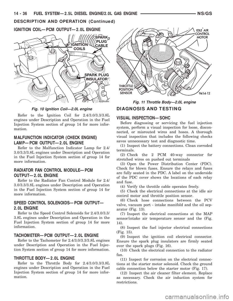
IGNITION COILÐPCM OUTPUTÐ2.0L ENGINE
Refer to the Ignition Coil for 2.4/3.0/3.3/3.8L
engines under Description and Operation in the Fuel
Injection System section of group 14 for more infor-
mation.
MALFUNCTION INDICATOR (CHECK ENGINE)
LAMPÐPCM OUTPUTÐ2.0L ENGINE
Refer to the Malfunction Indicator Lamp for 2.4/
3.0/3.3/3.8L engines under Description and Operation
in the Fuel Injection System section of group 14 for
more information.
RADIATOR FAN CONTROL MODULEÐPCM
OUTPUTÐ2.0L ENGINE
Refer to the Radiator Fan Control Module for 2.4/
3.0/3.3/3.8L engines under Description and Operation
in the Fuel Injection System section of group 14 for
more information.
SPEED CONTROL SOLENOIDSÐPCM OUTPUTÐ
2.0L ENGINE
Refer to the Speed Control Solenoids for 2.4/3.0/3.3/
3.8L engines under Description and Operation in the
Fuel Injection System section of group 14 for more
information.
TACHOMETERÐPCM OUTPUTÐ2.0L ENGINE
Refer to the Tachometer for 2.4/3.0/3.3/3.8L engines
under Description and Operation in the Fuel Injec-
tion System section of group 14 for more information.
THROTTLE BODYÐ2.0L ENGINE
Refer to the Throttle Body for 2.4/3.0/3.3/3.8L
engines under Description and Operation in the Fuel
Injection System section of group 14 for more infor-
mation.
DIAGNOSIS AND TESTING
VISUAL INSPECTIONÐSOHC
Before diagnosing or servicing the fuel injection
system, perform a visual inspection for loose, discon-
nected, or misrouted wires and hoses. A thorough
visual inspection that includes the following checks
saves unnecessary test and diagnostic time.
(1) Inspect the battery connections. Clean corroded
terminals.
(2) Check the 2 PCM 40-way connector for
stretched wires on pushed out terminals
(3) Open the Power Distribution Center (PDC).
Check for blown fuses. Ensure the relays and fuses
are fully seated in the PDC. A label on the underside
of the PDC cover shows the locations of each relay
and fuse.
(4) Verify the throttle cable operates freely.
(5) Check the electrical connections at the idle air
control motor and throttle position sensor.
(6) Check hose connections between the PCV
valve, vacuum port - intake manifold and the oil sep-
arator (Fig. 13).
(7) Inspect the electrical connections at the MAP
sensor/intake air temperature sensor and the (Fig.
14).
(8) Inspect the fuel injector electrical connections
(Fig. 15).
(9) Inspect the ignition coil electrical connector.
Ensure the spark plug insulators are firmly seated
over the spark plugs (Fig. 16).
(10) Check the electrical connection to the radiator
fan.
(11) Inspect for corrosion on the electrical connec-
tions at the starter motor solenoid. Check the ground
cable connection below the starter motor (Fig. 17).
(12) Inspect the air cleaner filter element. Replace
as necessary. Check the air induction system for
restrictions.
Fig. 10 Ignition CoilÐ2.0L engine
Fig. 11 Throttle BodyÐ2.0L engine
14 - 36 FUEL SYSTEMÐ2.5L DIESEL ENGINE/2.0L GAS ENGINENS/GS
DESCRIPTION AND OPERATION (Continued)
Page 1405 of 1938
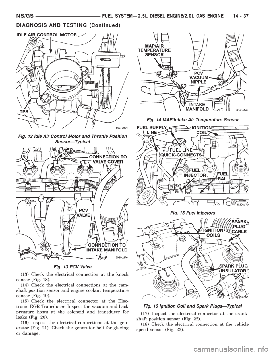
(13) Check the electrical connection at the knock
sensor (Fig. 18).
(14) Check the electrical connections at the cam-
shaft position sensor and engine coolant temperature
sensor (Fig. 19).
(15) Check the electrical connector at the Elec-
tronic EGR Transducer. Inspect the vacuum and back
pressure hoses at the solenoid and transducer for
leaks (Fig. 20).
(16) Inspect the electrical connections at the gen-
erator (Fig. 21). Check the generator belt for glazing
or damage.(17) Inspect the electrical connector at the crank-
shaft position sensor (Fig. 22).
(18) Check the electrical connection at the vehicle
speed sensor (Fig. 23).
Fig. 12 Idle Air Control Motor and Throttle Position
SensorÐTypical
Fig. 13 PCV Valve
Fig. 14 MAP/Intake Air Temperature Sensor
Fig. 15 Fuel Injectors
Fig. 16 Ignition Coil and Spark PlugsÐTypical
NS/GSFUEL SYSTEMÐ2.5L DIESEL ENGINE/2.0L GAS ENGINE 14 - 37
DIAGNOSIS AND TESTING (Continued)
Page 1406 of 1938
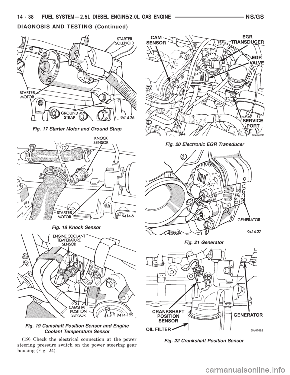
(19) Check the electrical connection at the power
steering pressure switch on the power steering gear
housing (Fig. 24).
Fig. 17 Starter Motor and Ground Strap
Fig. 18 Knock Sensor
Fig. 19 Camshaft Position Sensor and Engine
Coolant Temperature Sensor
Fig. 20 Electronic EGR Transducer
Fig. 21 Generator
Fig. 22 Crankshaft Position Sensor
14 - 38 FUEL SYSTEMÐ2.5L DIESEL ENGINE/2.0L GAS ENGINENS/GS
DIAGNOSIS AND TESTING (Continued)
Page 1407 of 1938
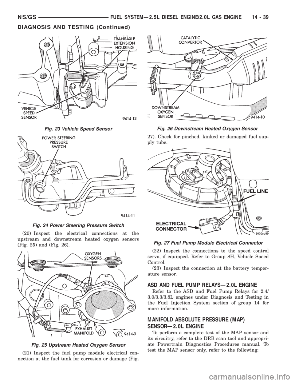
(20) Inspect the electrical connections at the
upstream and downstream heated oxygen sensors
(Fig. 25) and (Fig. 26).
(21) Inspect the fuel pump module electrical con-
nection at the fuel tank for corrosion or damage (Fig.27). Check for pinched, kinked or damaged fuel sup-
ply tube.
(22) Inspect the connections to the speed control
servo, if equipped. Refer to Group 8H, Vehicle Speed
Control.
(23) Inspect the connection at the battery temper-
ature sensor.
ASD AND FUEL PUMP RELAYSÐ2.0L ENGINE
Refer to the ASD and Fuel Pump Relays for 2.4/
3.0/3.3/3.8L engines under Diagnosis and Testing in
the Fuel Injection System section of group 14 for
more information.
MANIFOLD ABSOLUTE PRESSURE (MAP)
SENSORÐ2.0L ENGINE
To perform a complete test of the MAP sensor and
its circuitry, refer to the DRB scan tool and appropri-
ate Powertrain Diagnostics Procedures manual. To
test the MAP sensor only, refer to the following:
Fig. 23 Vehicle Speed Sensor
Fig. 24 Power Steering Pressure Switch
Fig. 25 Upstream Heated Oxygen Sensor
Fig. 26 Downstream Heated Oxygen Sensor
Fig. 27 Fuel Pump Module Electrical Connector
NS/GSFUEL SYSTEMÐ2.5L DIESEL ENGINE/2.0L GAS ENGINE 14 - 39
DIAGNOSIS AND TESTING (Continued)
Page 1409 of 1938

Connect the DVM between the center and sensor
ground terminal. Refer to Group 8W - Wiring Dia-
grams for correct pinout.
With the ignition switch in the ON position, check
the output voltage at the center terminal wire of the
connector. Check the output voltage at idle and at
Wide-Open-Throttle (WOT). At idle, TPS output volt-
age should be approximately 0.38 volts to 1.2 volts.
At wide open throttle, TPS output voltage should be
approximately 3.1 volts to 4.4 volts. The output volt-
age should gradually increase as the throttle plate
moves slowly from idle to WOT.
Check for spread terminals at the sensor and PCM
connections before replacing the TPS.
THROTTLE BODY MINIMUM AIR FLOW
(1) Turn ignition key to Off.
(2) D
isconnect the PCV valve hose from the intake
manifold nipple (Fig. 31). Cap the PCV vacuum nipple.
(3) Disconnect purge hose from the nipple on the
throttle body (Fig. 32).(4) Use a piece of hose to attach Air Metering Ori-
fice 6457 (0.125 in. orifice) to the purge nipple on the
throttle body (Fig. 33).
(5) Ensure that all accessories are off.
(6) Connect the DRB scan tool to the data link
connector inside the passenger compartment.
(7) Run engine in Park or Neutral until the cooling
fan has cycled on and off at least once (180ÉF).
(8) Using the DRB scan tool, access Minimum Air-
flow Idle Speed.
(9) The following will then occur:
²Idle air control motor will fully close
²Idle spark advance will become fixed
²PCM will go open loop enriched
²DRB scan tool displays engine RPM
(10) If idle RPM is within the range shown in the
Idle Specification chart, throttle body minimum air-
flow is set correctly.IDLE SPECIFICATION Ð2.0L ENGINE
Odometer Reading Idle RPM
Below 1000 Miles...............550±1300 RPM
Above 1000 Miles...............600±1300 RPM
(11) If idle RPM is above specifications, use the
DRB scan tool to check idle air control motor opera-
tion. If idle air control motor is OK, replace throttle
body. If idle air flow is below specification, shut off
the engine and clean the throttle body as follows:
WARNING: CLEAN THROTTLE BODY IN A WELL
VENTILATED AREA. WEAR RUBBER OR BUTYL
GLOVES, DO NOT LET MOPAR PARTS CLEANER
COME IN CONTACT WITH EYES OR SKIN. AVOID
INGESTING THE CLEANER. WASH THOROUGHLY
AFTER USING CLEANER.
Fig. 31 PCV Vacuum Nipple
Fig. 32 Purge Hose
Fig. 33 Orifice 6457 Attached to Purge Nipple
NS/GSFUEL SYSTEMÐ2.5L DIESEL ENGINE/2.0L GAS ENGINE 14 - 41
DIAGNOSIS AND TESTING (Continued)
Page 1419 of 1938

to Group 8W for wiring connector and circuitry infor-
mation. Repair the wire harness if an open circuit is
indicated.
(4) After tests are completed, connect electrical
connector to sensor.
GLOW PLUG TEST
Hard starting or a rough idle after starting may be
caused by one or more defective glow plugs. Before
testing the glow plugs, a test of the glow plug relay
should be performed. This will ensure that 12V+ is
available at the plugs when starting the engine.
Refer to the Glow Plug Relay Test for information.
For accurate test results, the glow plugs should be
removed from the engine. The plugs must be checked
when cold.Do not check the plugs if the engine
has recently been operated. If plugs are
checked when warm, incorrect amp gauge
readings will result.
Use Churchill Glow Plug Tester DX.900 or an
equivalent (Fig. 14) for the following tests. This
tester is equipped with 4 timer lamps.
(1) Remove the glow plugs from the engine. Refer
to Glow Plug Removal/Installation.
(2) Attach the red lead of the tester to the 12V+
(positive) side of the battery.
(3) Attach the black lead of the tester to the 12V±
(negative) side of the battery.
(4) Fit the glow plug into the top of the tester and
secure it with the spring loaded bar (Fig. 14).
(5) Attach the third lead wire of the tester to the
electrical terminal at the end of the glow plug.(6) When performing the test, the tester button
(Fig. 14) should be held continuously without release
for 20 seconds as indicated by the 4 timer lamps.
Each illuminated lamp represents a 5 second time
lapse.
(a) Press and hold the tester button (Fig. 14)
and note the amp gauge reading. The gauge read-
ing should indicate a momentary, initial current
draw (surge) of approximately 25 amps. After the
initial surge, the amp gauge reading should begin
to fall off. The glow plug tip should start to glow
an orange color after 5 seconds. If the tip did not
glow after 5 seconds, replace the glow plug. Before
discarding the glow plug, check the position of the
circuit breaker on the bottom of the plug tester. It
may have to be reset. Reset if necessary.
(b) Continue to hold the tester button while
observing the amp gauge and the 4 timer lamps.
When all 4 lamps are illuminated, indicating a 20
second time lapse, the amp gauge reading should
indicate a 9±12 amp current draw. If not, replace
the glow plug. Refer to Glow Plug Removal/Instal-
lation.
(7) Check each glow plug in this manner using one
20 second cycle. If the glow plug is to be retested, it
must first be allowed to cool to room temperature.
WARNING: THE GLOW PLUG WILL BECOME
EXTREMELY HOT (GLOWING) DURING THESE
TESTS. BURNS COULD RESULT IF IMPROPERLY
HANDLED. ALLOW THE GLOW PLUG TO COOL
BEFORE REMOVING FROM TESTER.
(8) Remove the glow plug from the tester.
GLOW PLUG RELAY TEST
The glow plug relay is located in the engine com-
partment on the left±inner fender (Fig. 15).
When the ignition (key) switch is placed in the ON
position, a signal is sent to the PCM relating current
engine coolant temperature. This signal is sent from
the engine coolant temperature sensor.
After receiving this signal, the PCM will deter-
mine if, when and for how long a period the glow
plug relay should be activated. This is done before,
during and after the engine is started. Whenever the
glow plug relay is activated, it will control the 12V+
100 amp circuit for the operation of the four glow
plugs.
The Glow Plug lamp is tied to this circuit. Lamp
operation is also controlled by the PCM.
With a cold engine, the glow plug relay and glow
plugs may be activated for a maximum time of 200
seconds. Refer to the Glow Plug Control chart for a
temperature/time comparison of glow plug relay oper-
ation.
Fig. 14 Typical Glow Plug Tester
NS/GSFUEL SYSTEMÐ2.5L DIESEL ENGINE/2.0L GAS ENGINE 14 - 51
DIAGNOSIS AND TESTING (Continued)
Page 1420 of 1938

In this chart, Pre±Heat and Post±Heat times are
mentioned. Pre±heat is the amount of time the glow
plug relay circuit is activated when the ignition (key)
switch is ON, but the engine has yet to be started.
Post±heat is the amount of time the glow plug relay
circuit is activated after the engine is operating. The
Glow Plug lamp will not be illuminated during the
post±heat cycle.
TESTING:
Disconnect and isolate the electrical connectors
(Fig. 16) at all four glow plugs. With the engine cool
or cold, and the key in the ON position, check for
10±12 volts + at each electrical connector. 10±12 volts
+ should be at each connector whenever the PCM is
operating in the pre±heat or post±heat cycles (refer
to the following Glow Plug Control chart).Be very
careful not to allow any of the four discon-
nected glow plug electrical connectors to con-
tact a metal surface. When the key is turned to
the ON position, approximately 100 amps at 12
volts is supplied to these connectors.If 10±12
volts + is not available at each connector, check con-
tinuity of wiring harness directly to the relay. If con-
tinuity is good directly to the relay, the fault is either
with the relay or the relay input from the PCM. To
test the relay only, refer to RelaysÐOperation/Test-
ing in this section of the group. If the relay test is
good, refer to the DRB scan tool.
Diagnostic Trouble Codes:Refer to On-Board
Diagnostics in Group 25, Emission Control System
for a list of Diagnostic Trouble Codes (DTC's) for cer-
tain fuel system components.
RELAYSÐOPERATION/TESTING
The following description of operation and
tests apply only to the Diesel PCM and other
relays. The terminals on the bottom of each relay
are numbered (Fig. 17).
OPERATION
²Terminal number 30 is connected to battery volt-
age. For both the Diesel and other relays, terminal
30 is connected to battery voltage at all times.
²The PCM grounds the coil side of the relay
through terminal number 85.
²Terminal number 86 supplies voltage to the coil
side of the relay.
²When the PCM de-energizes the Diesel PCM
and other relays, terminal number 87A connects to
terminal 30. This is the Off position. In the off posi-
tion, voltage is not supplied to the rest of the circuit.
Terminal 87A is the center terminal on the relay.
Fig. 15 Glow Plug Relay Location
Fig. 16 Wiring Connection at Glow Plug
GLOW PLUG CONTROL
14 - 52 FUEL SYSTEMÐ2.5L DIESEL ENGINE/2.0L GAS ENGINENS/GS
DIAGNOSIS AND TESTING (Continued)
Page 1421 of 1938

²When the PCM energizes the Diesel PCM and
other relays, terminal 87 connects to terminal 30.
This is the On position. Terminal 87 supplies voltage
to the rest of the circuit.
TESTING
The following procedure applies to the Diesel PCM
and other relays.
(1) Remove relay from connector before testing.
(2) With the relay removed from the vehicle, use
an ohmmeter to check the resistance between termi-
nals 85 and 86. The resistance should be between 75
65 ohms.
(3) Connect the ohmmeter between terminals 30
and 87A. The ohmmeter should show continuity
between terminals 30 and 87A.
(4) Connect the ohmmeter between terminals 87
and 30. The ohmmeter should not show continuity at
this time.
(5) Connect one end of a jumper wire (16 gauge or
smaller) to relay terminal 85. Connect the other end
of the jumper wire to the ground side of a 12 volt
power source.
(6) Connect one end of another jumper wire (16
gauge or smaller) to the power side of the 12 volt
power source.Do not attach the other end of the
jumper wire to the relay at this time.
WARNING: DO NOT ALLOW OHMMETER TO CON-
TACT TERMINALS 85 OR 86 DURING THIS TEST.
(7) Attach the other end of the jumper wire to
relay terminal 86. This activates the relay. The ohm-meter should now show continuity between relay ter-
minals 87 and 30. The ohmmeter should not show
continuity between relay terminals 87A and 30.
(8) Disconnect jumper wires.
(9) Replace the relay if it did not pass the continu-
ity and resistance tests. If the relay passed the tests,
it operates properly. Check the remainder of the Die-
sel PCM and other relay circuits. Refer to group 8W,
Wiring Diagrams.
BOOST PRESSURE SENSOR
If the boost pressure sensor fails, the PCM records
a DTC into memory and continues to operate the
engine in one of the three ªlimp-inº modes. When the
PCM is operating in this mode, a loss of power will
be present, as if the turbocharger was not operating.
The best method for diagnosing faults with the boost
pressure sensor is with the DRB III scan tool.
Diagnostic Trouble Codes:Refer to On-Board
Diagnostics in Group 25, Emission Control System
for a list of Diagnostic Trouble Codes (DTC's) for cer-
tain fuel system components.
VEHICLE SPEED SENSOR TEST
To perform a test of the sensor and its related cir-
cuitry, refer to DRB scan tool.
Diagnostic Trouble Codes:Refer to On-Board
Diagnostics in Group 25, Emission Control System
for a list of Diagnostic Trouble Codes (DTC's) for cer-
tain fuel system components.
DIAGNOSTIC TROUBLE CODES
For a list of Diagnostic Trouble Codes (DTC's),
refer to Group 25, Emission Control System for infor-
mation. See On-Board Diagnostics.
REMOVAL AND INSTALLATION
DIESEL PCM RELAY
The Diesel PCM relay is located in the PDC. For
the location of the relay within the PDC, refer to
label on PDC cover.
A/C CLUTCH RELAY
The A/C clutch relay is located in the PDC. For the
location of the relay within the PDC, refer to label on
PDC cover.
ENGINE SPEED SENSOR
The engine speed sensor is mounted to the trans-
mission bellhousing at the rear of the engine block
(Fig. 18).
REMOVAL
(1) Disconnect the harness (on the sensor) from
the main electrical harness.
Fig. 17 Diesel PCM and Other Relay Terminals
NS/GSFUEL SYSTEMÐ2.5L DIESEL ENGINE/2.0L GAS ENGINE 14 - 53
DIAGNOSIS AND TESTING (Continued)
Page 1423 of 1938

INSTALLATION
(1) Apply high±temperature anti±seize compound
to glow plug threads before installation
(2) Install the glow plug into the cylinder head.
Tighten to 23 N´m (203 in. lbs.) torque.
(3) Connect battery cable to battery.
GLOW PLUG RELAY
The glow plug relay is located in the engine com-
partment on the left±inner fender (Fig. 22).
REMOVAL
(1) Disconnect the negative battery cable at the
battery.
(2) Remove relay mounting bolt.(3) Disconnect electrical connector at relay and
remove relay.
INSTALLATION
(1) Check condition of electrical connector for dam-
age or corrosion. Repair as necessary.
(2) Install electrical connector to relay.
(3) Install relay to inner fender.
(4) Connect battery cable to battery.
POWERTRAIN CONTROL MODULE (PCM)
The PCM is mounted to a bracket located in the
center consule in front of the air bag module (Fig.
23).
REMOVAL
(1) Disconnect the negative battery cable at the
battery.
(2) Loosen the 68±Way connector (Fig. 23). The
electrical connector has a sliding bar which moves
inward to lock or outward to unlock.
(3) Remove the electrical connector by pulling
straight out.
(4) Remove PCM.
INSTALLATION
(1) After the PCM electrical connector has been
separated from the PCM, inspect the pins for corro-
sion, being spread apart, bent or misaligned. Also
inspect the pin heights in the connector. If the pin
heights are different, this would indicate a pin has
separated from the connector. Repair as necessary.
(2) Engage 68±way connector into PCM. Move
slide bar to lock connector.
(3) Connect negative cable to battery.
VEHICLE SPEED SENSOR
The vehicle speed sensor (Fig. 24) is located on the
extension housing of the transmission.
Fig. 21 Glow Plug Electrical Connector
Fig. 22 Glow Plug Relay Location
Fig. 23 PCM Location
NS/GSFUEL SYSTEMÐ2.5L DIESEL ENGINE/2.0L GAS ENGINE 14 - 55
REMOVAL AND INSTALLATION (Continued)