audio CHRYSLER VOYAGER 1996 User Guide
[x] Cancel search | Manufacturer: CHRYSLER, Model Year: 1996, Model line: VOYAGER, Model: CHRYSLER VOYAGER 1996Pages: 1938, PDF Size: 55.84 MB
Page 515 of 1938
VEHICLE THEFT SECURITY SYSTEM
CONTENTS
page page
GENERAL INFORMATION
INTRODUCTION......................... 1
DESCRIPTION AND OPERATION
ARMING PROCEDURE.................... 1
TIME-OUT PERIOD....................... 2
TRIGGERING THE VTSS................... 2
DIAGNOSIS AND TESTING
DIAGNOSTIC PROCEDURES................ 2
REMOVAL AND INSTALLATION
BODY CONTROL MODULE................. 2DOOR LOCK CYLINDER SWITCH............ 2
FRONT DOOR AJAR (VTSS TRIGGER)
SWITCH.............................. 2
HOOD AJAR (VTSS TRIGGER) SWITCH...... 3
LIFTGATE AJAR (VTSS TRIGGER) SWITCH.... 3
LIFTGATE LOCK CYLINDER SWITCH......... 3
SLIDING DOOR AJAR (VTSS TRIGGER)
SWITCH.............................. 4
GENERAL INFORMATION
INTRODUCTION
Vehicles equipped with the Vehicle Theft Security
System (VTSS) system, the doors, liftgate, hood and
ignition circuit are monitored by the Body Control
Module (BCM) when the system is armed. The VTSS
will prevent the engine from starting until the BCM
receives a disarm signal. If the VTSS is triggered,
the horn will pulse, headlamps/marker lamps will
flash, and the VTSS warning lamp will flash. If BCM
determines the threat to be false and the VTSS is not
triggered again, the system will shut down and
rearm itself after three minutes. The VTSS monitor-
ing portion of the system is split into two sections.
The engine compartment section and the passenger
compartment section. If a malfunction occurs in the
engine compartment section, the passenger compart-
ment section would still arm and function normally.
If an electrical malfunction occurs in either section of
the system a Diagnostic Trouble Code (DTC) would
be stored the BCM memory to aid system repair.
DTCs can be retrieved using scan tool (DRB)
attached to the diagnostic connector above the accel-
erator pedal.
ENABLING
To initialize the VTSS feature the operator must,
with the engine compartment hood open, cycle the
key in the liftgate key cylinder to the unlock position
giving the BCM a disarm signal. At this time the
visual alarm outputs the headlamps and marker
lamps will function. However the audio alarm output
the horn and engine disable portion of the VTSS will
not function until there has been twenty consecutiveengine run cycles. When this has occurred the total
VTSS will function.
If during alarm being set the BCM receives a
request from the RKE module to enter PANIC mode
the BCM will cancel the alarm, return VTSS armed
state and then perform the RKE PANIC feature.
DESCRIPTION AND OPERATION
ARMING PROCEDURE
METHOD-A
(1) With the key removed from the ignition lock
and any door open, actuate one of the following:
²Power door lock button to LOCK,
²Key fob LOCK button
²Door lock key cylinder to locked position.
(2) Close all opened doors.
(3) After the last door is closed, an arming time-
out period of sixteen seconds will start, then the
VTSS will become armed.
METHOD-B
Actuating the key fob transmitter LOCK button,
key locking the front doors or liftgate with the doors
closed and the ignition locked will begin the arming
time-out period. If method-A, 16 second time-out
sequence was in process when method-B was actu-
ated, the 16 second time-out will restart from the
time of the second actuation.
If the security lamp does not illuminate at all upon
final door closure, it indicates that the system is not
arming.
The current VTSS status armed or disarmed shall
be maintained in memory to prevent battery discon-
nects from disarming the system.
NSVEHICLE THEFT SECURITY SYSTEM 8Q - 1
Page 554 of 1938
²Rotate your hand-held transmitter end-over-end
and train again. For best results, place the end oppo-
site from the battery compartment against the uni-
versal transmitter while training.
²The frequency of the hand-held transmitter may
not be in the desired frequencies between 286MHz
and 399MHz set by FCC.
SERVICE PROCEDURES
COMPASS CALIBRATION PROCEDURE
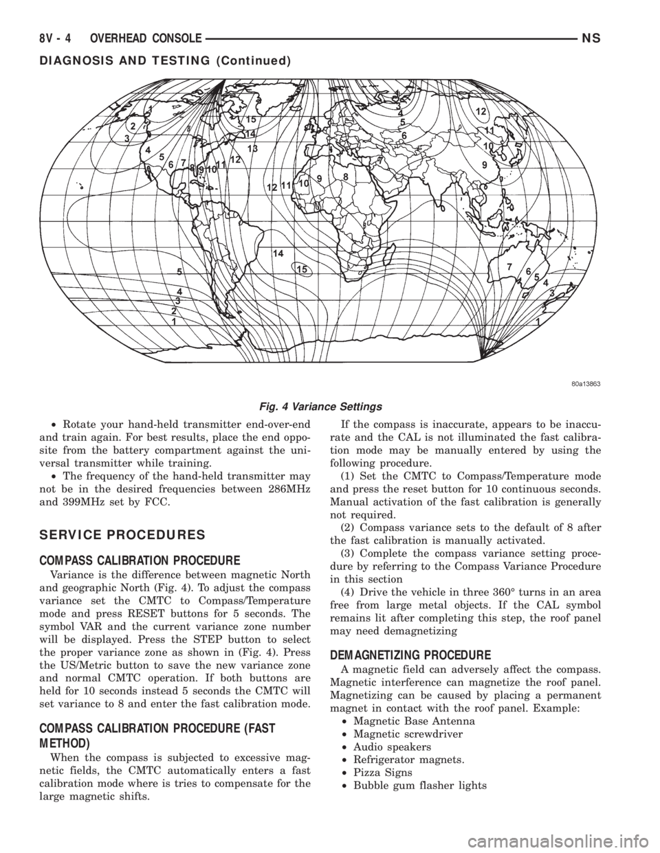
Variance is the difference between magnetic North
and geographic North (Fig. 4). To adjust the compass
variance set the CMTC to Compass/Temperature
mode and press RESET buttons for 5 seconds. The
symbol VAR and the current variance zone number
will be displayed. Press the STEP button to select
the proper variance zone as shown in (Fig. 4). Press
the US/Metric button to save the new variance zone
and normal CMTC operation. If both buttons are
held for 10 seconds instead 5 seconds the CMTC will
set variance to 8 and enter the fast calibration mode.
COMPASS CALIBRATION PROCEDURE (FAST
METHOD)
When the compass is subjected to excessive mag-
netic fields, the CMTC automatically enters a fast
calibration mode where is tries to compensate for the
large magnetic shifts.If the compass is inaccurate, appears to be inaccu-
rate and the CAL is not illuminated the fast calibra-
tion mode may be manually entered by using the
following procedure.
(1) Set the CMTC to Compass/Temperature mode
and press the reset button for 10 continuous seconds.
Manual activation of the fast calibration is generally
not required.
(2) Compass variance sets to the default of 8 after
the fast calibration is manually activated.
(3) Complete the compass variance setting proce-
dure by referring to the Compass Variance Procedure
in this section
(4) Drive the vehicle in three 360É turns in an area
free from large metal objects. If the CAL symbol
remains lit after completing this step, the roof panel
may need demagnetizing
DEMAGNETIZING PROCEDURE
A magnetic field can adversely affect the compass.
Magnetic interference can magnetize the roof panel.
Magnetizing can be caused by placing a permanent
magnet in contact with the roof panel. Example:
²Magnetic Base Antenna
²Magnetic screwdriver
²Audio speakers
²Refrigerator magnets.
²Pizza Signs
²Bubble gum flasher lights
Fig. 4 Variance Settings
8V - 4 OVERHEAD CONSOLENS
DIAGNOSIS AND TESTING (Continued)
Page 561 of 1938
WIRING DIAGRAMS
CONTENTS
page page
AIR CONDITIONING-HEATER.......... 8W-42-1
AIRBAG SYSTEM................... 8W-43-1
ANTI-LOCK BRAKES................. 8W-35-1
AUDIO SYSTEM.................... 8W-47-1
BODY CONTROL MODULE............ 8W-45-1
CHARGING SYSTEM................. 8W-20-1
COMPONENT INDEX................. 8W-02-1
CONNECTOR/GROUND LOCATIONS..... 8W-90-1
CONNECTOR PIN-OUTS.............. 8W-80-1
FRONT LIGHTING................... 8W-50-1
FUEL/IGNITION SYSTEM............. 8W-30-1
GENERAL INFORMATION............. 8W-01-1
GROUND DISTRIBUTION............. 8W-15-1
HORN/CIGAR LIGHTER/POWER OUTLET . 8W-41-1
INSTRUMENT CLUSTER.............. 8W-40-1
INTERIOR LIGHTING................. 8W-44-1
JUNCTION BLOCK................... 8W-12-1
MESSAGE CENTER.................. 8W-46-1OVERHEAD CONSOLE................ 8W-49-1
POWER DISTRIBUTION.............. 8W-10-1
POWER DOOR LOCKS............... 8W-61-1
POWER MIRRORS.................. 8W-62-1
POWER SEAT...................... 8W-63-1
POWER WINDOWS.................. 8W-60-1
REAR LIGHTING.................... 8W-51-1
SPLICE INFORMATION............... 8W-70-1
SPLICE LOCATIONS................. 8W-95-1
STARTING SYSTEM................. 8W-21-1
TRAILER TOW...................... 8W-54-1
TRANSMISSION CONTROL SYSTEM.... 8W-31-1
TURN SIGNALS..................... 8W-52-1
VEHICLE SPEED CONTROL........... 8W-33-1
VEHICLE THEFT SECURITY SYSTEM.... 8W-39-1
WINDOW DEFOGGERS............... 8W-48-1
WIPERS........................... 8W-53-1
NS/GSWIRING DIAGRAMS 8W - 1
Page 566 of 1938
CIRCUIT INFORMATION
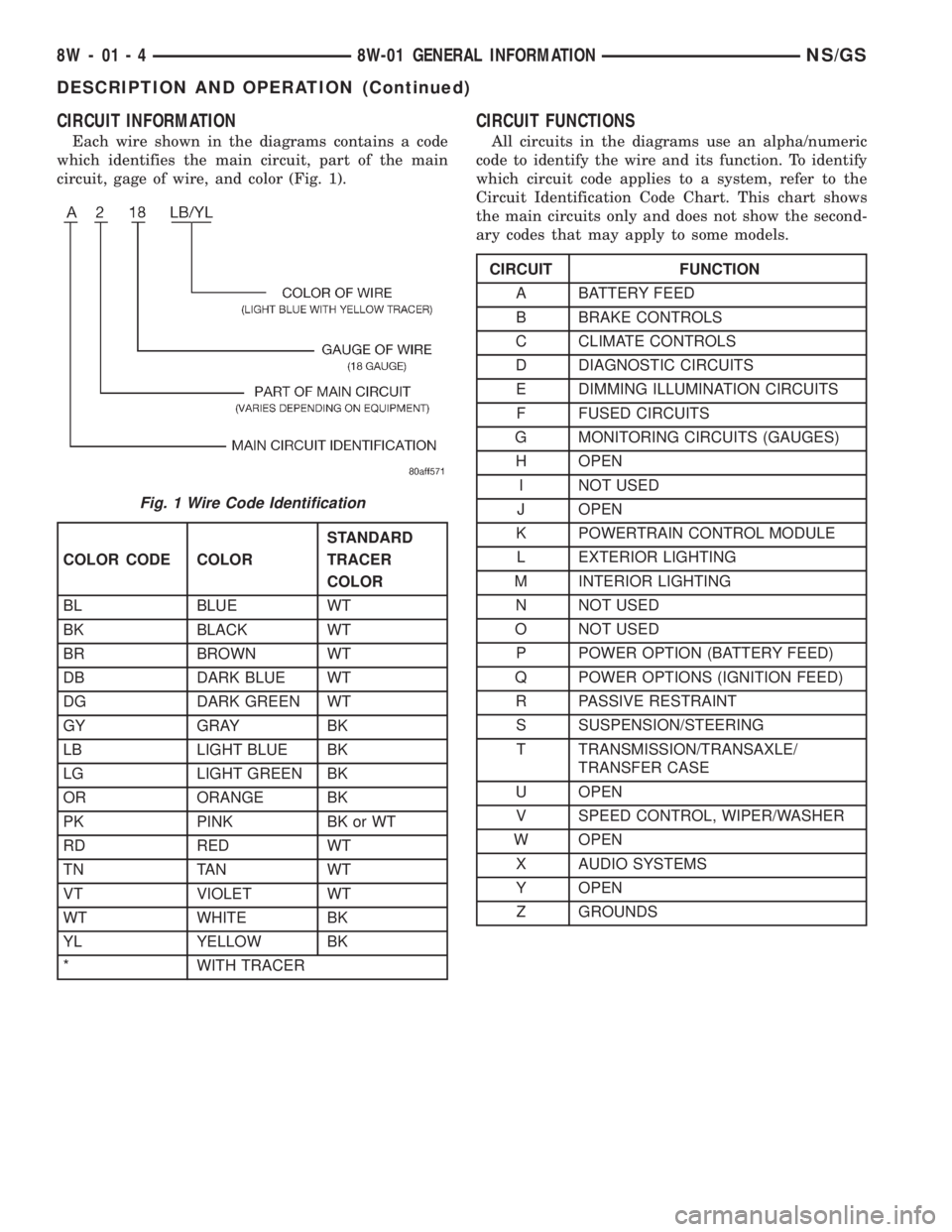
Each wire shown in the diagrams contains a code
which identifies the main circuit, part of the main
circuit, gage of wire, and color (Fig. 1).
CIRCUIT FUNCTIONS
All circuits in the diagrams use an alpha/numeric
code to identify the wire and its function. To identify
which circuit code applies to a system, refer to the
Circuit Identification Code Chart. This chart shows
the main circuits only and does not show the second-
ary codes that may apply to some models.
Fig. 1 Wire Code Identification
COLOR CODE COLORSTANDARD
TRACER
COLOR
BL BLUE WT
BK BLACK WT
BR BROWN WT
DB DARK BLUE WT
DG DARK GREEN WT
GY GRAY BK
LB LIGHT BLUE BK
LG LIGHT GREEN BK
OR ORANGE BK
PK PINK BK or WT
RD RED WT
TN TAN WT
VT VIOLET WT
WT WHITE BK
YL YELLOW BK
* WITH TRACER
CIRCUIT FUNCTION
A BATTERY FEED
B BRAKE CONTROLS
C CLIMATE CONTROLS
D DIAGNOSTIC CIRCUITS
E DIMMING ILLUMINATION CIRCUITS
F FUSED CIRCUITS
G MONITORING CIRCUITS (GAUGES)
H OPEN
I NOT USED
J OPEN
K POWERTRAIN CONTROL MODULE
L EXTERIOR LIGHTING
M INTERIOR LIGHTING
N NOT USED
O NOT USED
P POWER OPTION (BATTERY FEED)
Q POWER OPTIONS (IGNITION FEED)
R PASSIVE RESTRAINT
S SUSPENSION/STEERING
T TRANSMISSION/TRANSAXLE/
TRANSFER CASE
U OPEN
V SPEED CONTROL, WIPER/WASHER
W OPEN
X AUDIO SYSTEMS
Y OPEN
Z GROUNDS
8W - 01 - 4 8W-01 GENERAL INFORMATIONNS/GS
DESCRIPTION AND OPERATION (Continued)
Page 785 of 1938
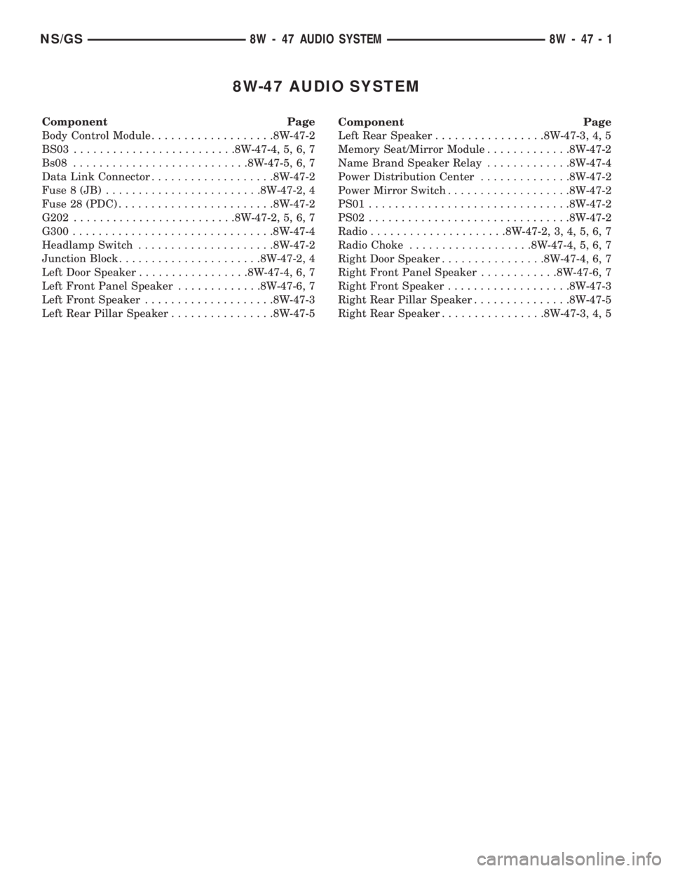
8W-47 AUDIO SYSTEM
Component Page
Body Control Module...................8W-47-2
BS03.........................8W-47-4, 5, 6, 7
Bs08...........................8W-47-5, 6, 7
Data Link Connector...................8W-47-2
Fuse 8 (JB)........................8W-47-2, 4
Fuse 28 (PDC)........................8W-47-2
G202.........................8W-47-2, 5, 6, 7
G300...............................8W-47-4
Headlamp Switch.....................8W-47-2
Junction Block......................8W-47-2, 4
Left Door Speaker.................8W-47-4, 6, 7
Left Front Panel Speaker.............8W-47-6, 7
Left Front Speaker....................8W-47-3
Left Rear Pillar Speaker................8W-47-5Component Page
Left Rear Speaker.................8W-47-3, 4, 5
Memory Seat/Mirror Module.............8W-47-2
Name Brand Speaker Relay.............8W-47-4
Power Distribution Center..............8W-47-2
Power Mirror Switch...................8W-47-2
PS01...............................8W-47-2
PS02...............................8W-47-2
Radio.....................8W-47-2, 3, 4, 5, 6, 7
Radio Choke...................8W-47-4, 5, 6, 7
Right Door Speaker................8W-47-4, 6, 7
Right Front Panel Speaker............8W-47-6, 7
Right Front Speaker...................8W-47-3
Right Rear Pillar Speaker...............8W-47-5
Right Rear Speaker................8W-47-3, 4, 5
NS/GS8W - 47 AUDIO SYSTEM 8W - 47 - 1
Page 786 of 1938

POWER
DISTRIBUTION
CENTER
28FUSE10A
BATT A0
C35
BLOCK
JUNCTION
C3
24
10A
FUSE
8
C211
BODY
CONTROL
MODULE
STEP
DIM
SWITCH
SIGNALB (+) FUSED
9 FEED LAMPSPANEL2
1C4C417
RUN-ACC A3113C1
M1
20
PK
C116
FUSED
B (+)
M1
20
PK
C16
RADIOFUSED
IGNITION
(RUN-ACC)
SIGNAL SWITCH DIMMERSTEP
4C1
PANEL
LAMPS
C15
FUSED
B (+)
C17
C15
SENSE SWITCH DIMMERSTEP
SWITCH
HEADLAMP
E17
20
YL/BK
E17
20
YL/BK
X12
18
RD/WT
5
POWER
MIRROR
SWITCH
E2
20
ORE2
20
OR
GROUND
G202
CCD
BUS
(+)
C31
(-) BUS CCD
2C3
D1
20
VT/BRD2
20
WT/BK
M1
20
PKM1
20
PK
16DATA
LINK
CONNECTOR MODULE MIRROR
SEAT/
MEMORY
TO
PS01 PS02
TO
6P50NOT
USEDX12
20
RD/WT
X15 16BK/DG
PANEL
LAMP
FEED
FEED(8W-10-9)
(8W-10-11)(8W-10-8)
(8W-12-2)
(8W-12-11)(8W-45-2)
(8W-45-4)
(8W-45-5) (8W-10-16)
(8W-50-9)
(8W-50-10) (8W-62-2)
(8W-62-4)
(8W-15-5)(8W-30-3)
(8W-30-30) (8W-62-3)
(8W-30-4) (8W-30-4) (8W-12-23)
8W - 47 - 2 8W-47 AUDIO SYSTEMNS/GS
J988W-3GS004702
Page 787 of 1938

RADIOLEFT
FRONT
(-)
C12
(+) FRONTLEFT
4C2
(+) REARLEFT
2C2
(-) REARLEFT
6C2
RIGHT
REAR
(-) RIGHT
REAR
(+)
C27C23
(+) FRONTRIGHT
(-) FRONTRIGHT
5C23C1
2
3
SPEAKER FRONT LEFT LEFT
REAR
SPEAKER
6 3
3
2
SPEAKER FRONT RIGHT
3
6
SPEAKER REAR
RIGHT
P34
B23
8 1079
X55
20
BR/RDX53
20
DGX51
20
BR/YL
X51
20
BR/YL
X57
20
BR/LB
X57
20
BR/LB
X52
20
DB/WT
X52
20
DB/WT
X58
20
DB/OR
X58
20
DB/OR
X54
20
VTX56
20
DB/RD
A9 A7 A10 A8
SPEAKER SPEAKER SPEAKER SPEAKER SPEAKER SPEAKER SPEAKER SPEAKER
NS/GS8W-47 AUDIO SYSTEM
BASE8W - 47 - 3
GS004703J988W-3
Page 788 of 1938

C122
BLOCK JUNCTION
8587
3086
2C2
RUN-ACC A31
1
2
RADIO
CHOKE
X1
16
DG/RD
G300
8Z1
14
BK
RADIO C3
13
OUTPUT12V RADIO
1C2
X60
20
RD/DG
X13
16
RD/DG
10A
FUSE
8
NAME
BRAND
SPEAKER
RELAY
5
LEFT
REAR
SPEAKER SPEAKERREAR
RIGHT
5
BS03
X13
16
RD/DGX13
16
RD/DG
5
RIGHT
DOOR
SPEAKER SPEAKER DOOR
LEFT
5
RD/DG16 X13
X13
16
RD/DG
14B03
D01P
RD/DG16
X13
RD/DG16
X13
2B01
D02
RADIO
CHOKE
OUTPUTRADIO
CHOKE
OUTPUTRADIO
CHOKE
OUTPUTRADIO
CHOKE
OUTPUT(8W-12-2) (8W-10-16)
(8W-15-6)(8W-12-11)
(8W-47-3)
(8W-47-5)(8W-47-3)
(8W-47-5) (8W-47-6)
(8W-47-7) (8W-47-6)
(8W-47-7) (8W-12-19)
8W - 47 - 4 8W-47 AUDIO SYSTEM
PREMIUMNS/GS
J988W-3GS004704
Page 789 of 1938

C26
RADIOLEFT
REAR
(-)
2 3
SPEAKER REAR
LEFT
6
A7 A9
2C2
(+) REARLEFT
362
A8 A10
C273C2
RIGHT
REAR
(-) (+) REAR RIGHT
SPEAKER
REAR
RIGHT
7910 8
2
1
SPEAKER PILLAR
REAR
LEFT
RIGHT
REAR
PILLAR
SPEAKER
2 1
X57
20
BR/LB
X57
20
BR/LB
X157
20
BR/LB
X51
20
BR/YL
X51
20
BR/YL
X151
20
BR/YL
X52
20
DB/WT
X52
20
DB/WT
X152
20
DB/WT
X58
20
DB/OR
X58
20
DB/OR
X158
20
DB/OR
G202
P34 B2311 A11
X15
16
BK/DG
BS08
BK/DG16 X15
X15
16
BK/DG
X15
16
BK/DG
2
CHOKE RADIO
541541
X13
16
RD/DG
X13
16
RD/DGX13
16
RD/DG
BS03
SPEAKER SPEAKER SPEAKER SPEAKERRADIO
CHOKE
OUTPUT
(8W-15-5) (8W-15-5) (8W-47-4)
(8W-47-4)
NS/GS8W-47 AUDIO SYSTEM
PREMIUM8W - 47 - 5
GS004705J988W-3
Page 790 of 1938

C12
RADIOLEFT
DOOR
(-)
5
2 3
SPEAKER DOOR
LEFT
6
A14 A12
4C2
(+) DOORLEFT
362 5
A15 A13
C135C2
RIGHT
DOOR
(-) (+) DOOR RIGHT
SPEAKER
DOOR
RIGHT
14 12 13 15
4
1
SPEAKER PANEL
FRONT
LEFTRIGHT
FRONT
PANEL
SPEAKER
1 4
X13
16
RD/DGX13
16
RD/DG
X55
20
BR/RD
X55
20
BR/RD
X155
20
BR/WT
X53
20
DG
X53
20
DG
X153
20
WT/BR
X54
20
VT
X54
20
VT
X156
20
VT/WT
X56
20
DB/RD
X56
20
DB/RD
X154
20
WT/VT
G202
P34 B2311 A11
X15
16
BK/DG
BS08
BK/DG16 X15
X15
16
BK/DG
X15
16
BK/DG
D02
B012D01P
B0314
RD/DG16 X13
RD/DG16 X13
1
1D02
B01D01P
B03
BS03
2
CHOKE RADIO
B26
P18
B23
B6
D02 B12073
14 41
510B01
D02
B2B23 P18B25
X153
20
WT/BRX155
20
BR/WT
25 2626
X154
20
WT/VT
X156
20
VT/WT
X13
16
RD/DG
897 8
SPEAKER SPEAKER SPEAKER SPEAKEROUTPUTRADIO
CHOKE(8W-15-5) (8W-15-5) (8W-47-4)
(8W-47-4)
8W - 47 - 6 8W-47 AUDIO SYSTEM
PREMIUM LHDNS/GS
J988W-3GS004706