diagram CHRYSLER VOYAGER 1996 User Guide
[x] Cancel search | Manufacturer: CHRYSLER, Model Year: 1996, Model line: VOYAGER, Model: CHRYSLER VOYAGER 1996Pages: 1938, PDF Size: 55.84 MB
Page 267 of 1938

²Body Control Module
²Remote Keyless Entry Module
(8) Disconnect one component at time, to see if any
component is at fault. If the high reading is not elim-
inated there is a short circuit in the wiring. Refer to
Group 8W, wiring diagrams.
(9) Remove interior and brake lamp fuses. Install
the fuses. The milliampere reading should be 2-4 mA.
If reading is higher than 4 mA:
(a) Disconnect PCM.
(b) If reading is OK, replace PCM.
(c) If reading does not change there is a short
circuit to the PCM. Refer to Group 8W, Wiring Dia-
grams.
BATTERY LOAD TEST
A fully charged battery must have cranking capac-
ity, to provide the starter motor and ignition system
enough power to start the engine over a broad range
of ambient temperatures. A battery load test will ver-
ify the actual cranking capability of the battery.
WARNING: IF BATTERY SHOWS SIGNS OF FREEZ-
ING, LEAKING, LOOSE POSTS, OR EXCESSIVELY
LOW ELECTROLYTE LEVEL, DO NOT TEST. ACID
BURNS OR AN EXPLOSIVE CONDITION MAY
RESULT.
(1) Remove both battery cables, negative cable
first. The battery top, cables and posts should be
clean. Test battery with a hydrometer. If battery
charge is low the charge battery. Refer to Battery
Charging Procedures.(2) Connect a Volt/Ammeter/Load tester to the bat-
tery posts (Fig. 6). Rotate the load control knob of the
Carbon pile rheostat to apply a 300 amp load. Apply
this load for 15 seconds to remove the surface charge
from the battery, and return the control knob to off
(Fig. 7).
(3) Allow the battery to stabilize for 2 minutes,
and then verify open circuit voltage.
(4) Rotate the load control knob on the tester to
maintain 50% of the battery cold crank rating for 15
seconds (Fig. 8). Record the loaded voltage reading
and return the load control to off. Refer to the Bat-
tery Specifications at the rear of this Group.
(5) Voltage drop will vary according to battery
temperature at the time of the load test. Battery
temperature can be estimated by the temperature of
exposure over the preceding several hours. If the bat-
tery has been charged or boosted a few minutes prior
to the test, the battery would be slightly warmer.
Refer to Load Test Voltage Chart for proper loaded
voltage reading.
Fig. 5 Milliampere Meter ConnectionFig. 6 Volt-Ammeter Load Tester Connections
Fig. 7 Remove Surface Charge From Battery
NS/GSBATTERY 8A - 5
DIAGNOSIS AND TESTING (Continued)
Page 275 of 1938
vehicles with a manual transmission, the clutch
pedal must be fully depressed for this test. Check for
battery voltage at the cavity for relay terminal 86
with the ignition switch in the Start position, and no
voltage when the ignition switch is released to the
On position. If OK, go to Step 5. If not OK with an
automatic transmission, check for an open or short
circuit to the ignition switch and repair, if required.
If the circuit to the ignition switch is OK, see the
Ignition Switch Test procedure in this group. If not
OK with a manual transmission, check the circuit
between the relay and the clutch pedal position
switch for an open or a short. If the circuit is OK, see
the Clutch Pedal Position Switch Test procedure in
this group.
(5) The coil ground terminal (85) is connected to
the electromagnet in the relay. On vehicles with an
automatic transmission, it is grounded through the
park/neutral position switch only when the gearshift
selector lever is in the Park or Neutral positions. On
vehicles with a manual transmission, it is grounded
at all times. Check for continuity to ground at the
cavity for relay terminal 85. If not OK with an auto-
matic transmission, check for an open or short circuit
to the park/neutral position switch and repair, if
required. If the circuit is OK, see the Park/Neutral
Position Switch Test procedure in this group. If not
OK with a manual transmission, repair the circuit to
ground as required.
SAFETY SWITCHES
For diagnostics,
²Clutch Pedal Position Switch, refer to Group 6,
Clutch.
²Park/Neutral Position Switch, refer to Group 21,
Transaxle
IGNITION SWITCH
After testing starter solenoid and relay, test igni-
tion switch and wiring. Refer to Group 8D, Ignition
Systems or Group 8W, Wiring Diagrams. Check all
wiring for opens or shorts, and all connectors for
being loose or corroded.
BATTERY
Refer to Group 8A, Battery for proper procedures.
ALL RELATED WIRING AND CONNECTORS
Refer to Group 8W, Wiring Diagrams,
FEED CIRCUIT RESISTANCE TEST
Before proceeding with this operation, review Diag-
nostic Preparation and Starter Feed Circuit Tests.
The following operation will require a voltmeter,
accurate to 1/10 of a volt.
CAUTION: Before performing any starter tests, the
ignition and fuel systems must be disabled.
(1) To disable the ignition and fuel systems, dis-
connect the Automatic Shutdown Relay (ASD). The
ASD relay is located in the Power Distribution Cen-
ter (PDC). Refer to the PDC cover for proper relay
location.
(2) With all wiring harnesses and components
properly connected, perform the following:
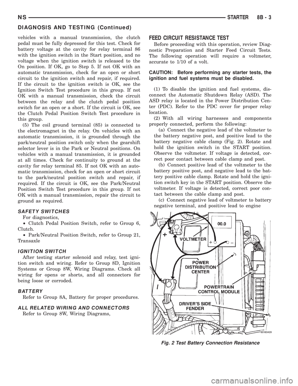
(a) Connect the negative lead of the voltmeter to
the battery negative post, and positive lead to the
battery negative cable clamp (Fig. 2). Rotate and
hold the ignition switch in the START position.
Observe the voltmeter. If voltage is detected, cor-
rect poor contact between cable clamp and post.
(b) Connect positive lead of the voltmeter to the
battery positive post, and negative lead to the bat-
tery positive cable clamp. Rotate and hold the igni-
tion switch key in the START position. Observe the
voltmeter. If voltage is detected, correct poor con-
tact between the cable clamp and post.
(c) Connect negative lead of voltmeter to battery
negative terminal, and positive lead to engine
Fig. 2 Test Battery Connection Resistance
NSSTARTER 8B - 3
DIAGNOSIS AND TESTING (Continued)
Page 287 of 1938
CHARGING SYSTEM
CONTENTS
page page
GENERAL INFORMATION
OVERVIEW............................. 1
DESCRIPTION AND OPERATION
BATTERY TEMPERATURE SENSOR.......... 2
CHARGING SYSTEM OPERATION........... 1
ELECTRONIC VOLTAGE REGULATOR......... 2
GENERATOR............................ 2
DIAGNOSIS AND TESTING
CHARGING SYSTEM RESISTANCE TESTS..... 4
CHARGING SYSTEM...................... 2CURRENT OUTPUT TEST.................. 4
ON-BOARD DIAGNOSTIC SYSTEM TEST...... 7
REMOVAL AND INSTALLATION
GENERATORÐ2.4L ENGINE................ 9
GENERATORÐ3.0L ENGINE................ 9
GENERATORÐ3.3/3.8 L ENGINE........... 10
SPECIFICATIONS
GENERATOR........................... 11
TORQUE.............................. 11
GENERAL INFORMATION
OVERVIEW
The battery, starting, and charging systems oper-
ate with one another, and must be tested as a com-
plete system. In order for the vehicle to start and
charge properly, all of the components involved in
these systems must perform within specifications.
Group 8A covers the battery, Group 8B covers the
starting system, and Group 8C covers the charging
system. Refer to Group 8W - Wiring Diagrams for
complete circuit descriptions and diagrams. We have
separated these systems to make it easier to locate
the information you are seeking within this Service
Manual. However, when attempting to diagnose any
of these systems, it is important that you keep their
interdependency in mind.
The diagnostic procedures used in these groups
include the most basic conventional diagnostic meth-
ods to the more sophisticated On-Board Diagnostics
(OBD) built into the Powertrain Control Module
(PCM). Use of an induction ammeter, volt/ohmmeter,
battery charger, carbon pile rheostat (load tester),
and 12-volt test lamp may be required.
All OBD-sensed systems are monitored by the
PCM. Each monitored circuit is assigned a Diagnos-
tic Trouble Code (DTC). The PCM will store a DTC in
electronic memory for any failure it detects. See the
On-Board Diagnostics Test in Group 8C - Charging
System for more information.
DESCRIPTION AND OPERATION
CHARGING SYSTEM OPERATION
The charging system consists of:
²Generator
²Electronic Voltage Regulator (EVR) circuitry
within the Powertrain Control Module (PCM)
²Ignition switch (refer to Group 8D, Ignition Sys-
tem for information)
²Battery (refer to Group 8A, Battery for informa-
tion)
²Temperature is measured by a sensor in the
PCM circuitry
²Wiring harness and connections (refer to Group
8W, Wiring for information)
The charging system is turned on and off with the
ignition switch. When the ignition switch is turned to
the ON position, battery voltage is applied to the
generator rotor through one of the two field termi-
nals to produce a magnetic field. The generator is
driven by the engine through a serpentine belt and
pulley arrangement.
The amount of DC current produced by the gener-
ator is controlled by the EVR (field control) circuitry,
contained within the PCM. This circuitry is con-
nected in series with the second rotor field terminal
and ground.
All vehicles are equipped with On-Board Diagnos-
tics (OBD). All OBD-sensed systems, including the
EVR (field control) circuitry, are monitored by the
PCM. Each monitored circuit is assigned a Diagnos-
tic Trouble Code (DTC). The PCM will store a DTC in
electronic memory for any failure it detects. See On-
Board Diagnostic System Test in this group for more
information.
NSCHARGING SYSTEM 8C - 1
Page 308 of 1938

(3) Remove ignition cables from the secondary tow-
ers of the coil. Measure the secondary resistance of
the coil between the towers of each individual coil
(Fig. 21). Secondary resistance should be 7,000 to
15,800 ohms. Replace the coil if resistance is not
within tolerance.
FAILURE TO START TEST
This no-start test checks the camshaft position sen-
sor and crankshaft position sensor.
The Powertrain Control Module (PCM) supplies 8
volts to the camshaft position sensor and crankshaft
position sensor through one circuit. If the 8 volt sup-
ply circuit shorts to ground, neither sensor will pro-
duce a signal (output voltage to the PCM).
When the ignition key is turned and left in the On
position, the PCM automatically energizes the Auto
Shutdown (ASD) relay. However, the controller de-en-
ergizes the relay within one second because it has
not received a camshaft position sensor signal indi-
cating engine rotation.
During cranking, the ASD relay will not energize
until the PCM receives a camshaft position sensor
signal. Secondly, the ASD relay remains energized
only if the controller senses a crankshaft position
sensor signal immediately after detecting the cam-
shaft position sensor signal.
(1) Check battery voltage. Voltage should be
approximately 12.66 volts or higher to perform fail-
ure to start test.
(2) Disconnect the harness connector from the coil
pack.
(3) Connect a test light to the B+ (battery voltage)
terminal of the coil electrical connector and ground
as shown in (Fig. 22). The B+ wire for the DIS coil is
dark green with an orange tracer.Do not spread
the terminal with the test light probe.(4) Turn the ignition key to theON position.The
test light should flash On and then Off.Do not turn
the Key to off position, leave it in the On posi-
tion.
(a) If the test light flashes momentarily, the
PCM grounded the Auto Shutdown (ASD) relay.
Proceed to step 5.
(b) If the test light did not flash, the ASD relay
did not energize. The cause is either the relay or
one of the relay circuits. Use the DRB scan tool to
test the ASD relay and circuits. Refer to the appro-
priate Powertrain Diagnostics Procedure Manual.
Refer to the wiring diagrams section for circuit
information.
(5) Crank the engine. (If the key was placed in the
off position after step 4, place the key in the On posi-
tion before cranking. Wait for the test light to flash
once, then crank the engine.)
(6) If the test light momentarily flashes during
cranking, the PCM is not receiving a crankshaft posi-
tion sensor signal. Use the DRB scan tool to test the
crankshaft position sensor and sensor circuits. Refer
to the appropriate Powertrain Diagnostics Procedure
Manual. Refer to the wiring diagrams section for cir-
cuit information.
(7) If the test light did not flash during cranking,
unplug the crankshaft position sensor connector.
Turn the ignition key to the off position. Turn the
key to the On position, wait for the test light to
momentarily flash once, then crank the engine. If the
test light momentarily flashes, the crankshaft posi-
tion sensor is shorted and must be replaced. If the
light did not flash, the cause of the no-start is in
Fig. 21 Checking Ignition Coil Secondary
ResistanceFig. 22 Ignition Coil Engine Harness Connector
8D - 10 IGNITION SYSTEMNS
DIAGNOSIS AND TESTING (Continued)
Page 309 of 1938
either the crankshaft position sensor/camshaft posi-
tion sensor 8 volt supply circuit, or the camshaft
position sensor output or ground circuits. Use the
DRB scan tool to test the camshaft position sensor
and the sensor circuits. Refer to the appropriate Pow-
ertrain Diagnostics Procedure Manual. Refer to the
wiring diagrams section for circuit information.
IGNITION TIMING PROCEDURE
The engines for this vehicle, use a fixed ignition
system. The PCM regulates ignition timing. Basic
ignition timing is not adjustable.
MANIFOLD ABSOLUTE PRESSURE (MAP) SENSOR
TEST
Refer to Group 14, Fuel System for Diagnosis and
Testing.
CAMSHAFT POSITION SENSOR AND CRANKSHAFT
POSITION SENSOR
The output voltage of a properly operating cam-
shaft position sensor or crankshaft position sensor
switches from high (5.0 volts) to low (0.3 volts). By
connecting an Moper Diagonostic System (MDS) and
engine analyzer to the vehicle, technicians can view
the square wave pattern.
ENGINE COOLANT TEMPERATURE SENSOR
Refer to Group 14, Fuel System for Diagnosis and
Testing.
INTAKE AIR TEMPERATURE SENSOR
Refer to Group 14, Fuel System, for Diagnosis and
Testing.
SPARK PLUG CONDITION
NORMAL OPERATING CONDITIONS
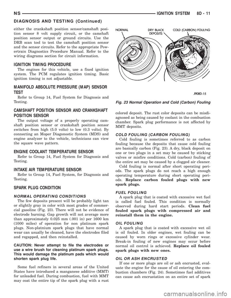
The few deposits present will be probably light tan
or slightly gray in color with most grades of commer-
cial gasoline (Fig. 23). There will not be evidence of
electrode burning. Gap growth will not average more
than approximately 0.025 mm (.001 in) per 1600 km
(1000 miles) of operation for non platinum spark
plugs. Non-platnium spark plugs that have normal
wear can usually be cleaned, have the electrodes filed
and regapped, and then reinstalled.
CAUTION: Never attempt to file the electrodes or
use a wire brush for cleaning platinum spark plugs.
This would damage the platinum pads which would
shorten spark plug life.
Some fuel refiners in several areas of the United
States have introduced a manganese additive (MMT)
for unleaded fuel. During combustion, fuel with MMT
may coat the entire tip of the spark plug with a rustcolored deposit. The rust color deposits can be misdi-
agnosed as being caused by coolant in the combustion
chamber. Spark plug performance is not affected by
MMT deposits.
COLD FOULING (CARBON FOULING)
Cold fouling is sometimes referred to as carbon
fouling because the deposits that cause cold fouling
are basically carbon (Fig. 23). A dry, black deposit on
one or two plugs in a set may be caused by sticking
valves or misfire conditions. Cold (carbon) fouling of
the entire set may be caused by a clogged air cleaner.
Cold fouling is normal after short operating peri-
ods. The spark plugs do not reach a high enough
operating temperature during short operating peri-
ods.Replace carbon fouled plugs with new
spark plugs.
FUEL FOULING
A spark plug that is coated with excessive wet fuel
is called fuel fouled. This condition is normally
observed during hard start periods.Clean fuel
fouled spark plugs with compressed air and
reinstall them in the engine.
OIL FOULING
A spark plug that is coated with excessive wet oil
is oil fouled. In older engines, wet fouling can be
caused by worn rings or excessive cylinder wear.
Break-in fouling of new engines may occur before
normal oil control is achieved.Replace oil fouled
spark plugs with new ones.
OIL OR ASH ENCRUSTED
If one or more plugs are oil or ash encrusted, eval-
uate the engine for the cause of oil entering the com-
bustion chambers (Fig. 24). Sometimes fuel additives
can cause ash encrustation on an entire set of spark
Fig. 23 Normal Operation and Cold (Carbon) Fouling
NSIGNITION SYSTEM 8D - 11
DIAGNOSIS AND TESTING (Continued)
Page 325 of 1938
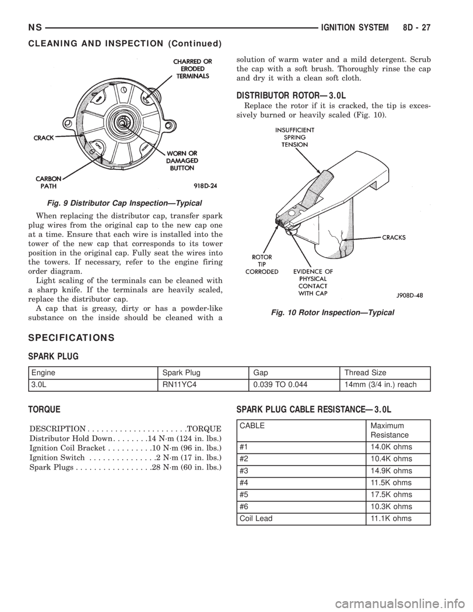
When replacing the distributor cap, transfer spark
plug wires from the original cap to the new cap one
at a time. Ensure that each wire is installed into the
tower of the new cap that corresponds to its tower
position in the original cap. Fully seat the wires into
the towers. If necessary, refer to the engine firing
order diagram.
Light scaling of the terminals can be cleaned with
a sharp knife. If the terminals are heavily scaled,
replace the distributor cap.
A cap that is greasy, dirty or has a powder-like
substance on the inside should be cleaned with asolution of warm water and a mild detergent. Scrub
the cap with a soft brush. Thoroughly rinse the cap
and dry it with a clean soft cloth.
DISTRIBUTOR ROTORÐ3.0L
Replace the rotor if it is cracked, the tip is exces-
sively burned or heavily scaled (Fig. 10).
SPECIFICATIONS
SPARK PLUG
TORQUE
DESCRIPTION......................TORQUE
Distributor Hold Down........14N´m(124 in. lbs.)
Ignition Coil Bracket..........10N´m(96in.lbs.)
Ignition Switch...............2N´m(17in.lbs.)
Spark Plugs.................28N´m(60in.lbs.)
SPARK PLUG CABLE RESISTANCEÐ3.0L
Fig. 9 Distributor Cap InspectionÐTypical
Fig. 10 Rotor InspectionÐTypical
Engine Spark Plug Gap Thread Size
3.0L RN11YC4 0.039 TO 0.044 14mm (3/4 in.) reach
CABLE Maximum
Resistance
#1 14.0K ohms
#2 10.4K ohms
#3 14.9K ohms
#4 11.5K ohms
#5 17.5K ohms
#6 10.3K ohms
Coil Lead 11.1K ohms
NSIGNITION SYSTEM 8D - 27
CLEANING AND INSPECTION (Continued)
Page 333 of 1938
IGNITION SWITCH AND LOCK CYLINDER
INDEX
page page
DESCRIPTION AND OPERATION
IGNITION INTERLOCK.................... 35
LOCK KEY CYLINDER.................... 35
REMOVAL AND INSTALLATION
IGNITION INTERLOCK.................... 38IGNITION SWITCH....................... 35
LOCK CYLINDER HOUSING............... 38
LOCK KEY CYLINDER.................... 38
DESCRIPTION AND OPERATION
IGNITION INTERLOCK
All vehicles equipped with automatic transaxles
have an interlock system. The system prevents shift-
ing the vehicle out of Park unless the ignition lock
cylinder is in the Off, Run or Start position. In addi-
tion, the operator cannot rotate the key to the lock
position unless the shifter is in the park position. On
vehicles equipped with floor shift refer to Group 21 -
Transaxle for Automatic Transmission Shifter/Igni-
tion Interlock.
LOCK KEY CYLINDER
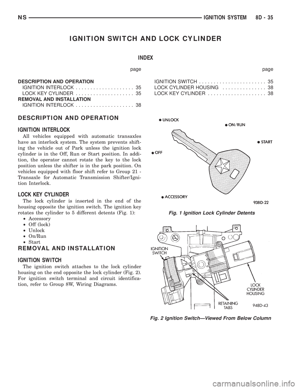
The lock cylinder is inserted in the end of the
housing opposite the ignition switch. The ignition key
rotates the cylinder to 5 different detents (Fig. 1):
²Accessory
²Off (lock)
²Unlock
²On/Run
²Start
REMOVAL AND INSTALLATION
IGNITION SWITCH
The ignition switch attaches to the lock cylinder
housing on the end opposite the lock cylinder (Fig. 2).
For ignition switch terminal and circuit identifica-
tion, refer to Group 8W, Wiring Diagrams.
Fig. 1 Ignition Lock Cylinder Detents
Fig. 2 Ignition SwitchÐViewed From Below Column
NSIGNITION SYSTEM 8D - 35
Page 406 of 1938
TEST 2
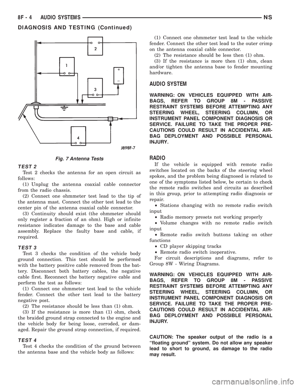
Test 2 checks the antenna for an open circuit as
follows:
(1) Unplug the antenna coaxial cable connector
from the radio chassis.
(2) Connect one ohmmeter test lead to the tip of
the antenna mast. Connect the other test lead to the
center pin of the antenna coaxial cable connector.
(3) Continuity should exist (the ohmmeter should
only register a fraction of an ohm). High or infinite
resistance indicates damage to the base and cable
assembly. Replace the faulty base and cable, if
required.
TEST 3
Test 3 checks the condition of the vehicle body
ground connection. This test should be performed
with the battery positive cable removed from the bat-
tery. Disconnect both battery cables, the negative
cable first. Reconnect the battery negative cable and
perform the test as follows:
(1) Connect one ohmmeter test lead to the vehicle
fender. Connect the other test lead to the battery
negative post.
(2) The resistance should be less than (1) ohm.
(3) If the resistance is more than (1) ohm, check
the braided ground strap connected to the engine and
the vehicle body for being loose, corroded, or dam-
aged. Repair the ground strap connection, if required.
TEST 4
Test 4 checks the condition of the ground between
the antenna base and the vehicle body as follows:(1) Connect one ohmmeter test lead to the vehicle
fender. Connect the other test lead to the outer crimp
on the antenna coaxial cable connector.
(2) The resistance should be less then (1) ohm.
(3) If the resistance is more then (1) ohm, clean
and/or tighten the antenna base to fender mounting
hardware.
AUDIO SYSTEM
WARNING: ON VEHICLES EQUIPPED WITH AIR-
BAGS, REFER TO GROUP 8M - PASSIVE
RESTRAINT SYSTEMS BEFORE ATTEMPTING ANY
STEERING WHEEL, STEERING COLUMN, OR
INSTRUMENT PANEL COMPONENT DIAGNOSIS OR
SERVICE. FAILURE TO TAKE THE PROPER PRE-
CAUTIONS COULD RESULT IN ACCIDENTAL AIR-
BAG DEPLOYMENT AND POSSIBLE PERSONAL
INJURY.
RADIO
If the vehicle is equipped with remote radio
switches located on the backs of the steering wheel
spokes, and the problem being diagnosed is related to
one of the symptoms listed below, be certain to check
the remote radio switches and circuits as described
in this group, prior to attempting radio diagnosis or
repair.
²Stations changing with no remote radio switch
input
²Radio memory presets not working properly
²Volume changes with no remote radio switch
input
²Remote radio switch buttons taking on other
functions
²CD player skipping tracks
²Remote radio switch inoperative.
For circuit descriptions and diagrams, refer to
Group 8W - Wiring Diagrams.
WARNING: ON VEHICLES EQUIPPED WITH AIR-
BAGS, REFER TO GROUP 8M - PASSIVE
RESTRAINT SYSTEMS BEFORE ATTEMPTING ANY
STEERING WHEEL, STEERING COLUMN, OR
INSTRUMENT PANEL COMPONENT DIAGNOSIS OR
SERVICE. FAILURE TO TAKE THE PROPER PRE-
CAUTIONS COULD RESULT IN ACCIDENTAL AIR-
BAG DEPLOYMENT AND POSSIBLE PERSONAL
INJURY.
CAUTION: The speaker output of the radio is a
ªfloating groundº system. Do not allow any speaker
lead to short to ground, as damage to the radio
may result.
Fig. 7 Antenna Tests
8F - 4 AUDIO SYSTEMSNS
DIAGNOSIS AND TESTING (Continued)
Page 413 of 1938

HORNS
CONTENTS
page page
DESCRIPTION AND OPERATION
INTRODUCTION......................... 1
DIAGNOSIS AND TESTING
HORN RELAY........................... 1
HORN SYSTEM.......................... 3
HORN SYSTEM TEST..................... 3HORN................................. 1
HORNS SOUND CONTINUOUSLY............ 3
HORNS WILL NOT SOUND................ 2
REMOVAL AND INSTALLATION
HORN SWITCH.......................... 4
HORNS................................ 4
DESCRIPTION AND OPERATION
INTRODUCTION
WARNING: ON VEHICLES EQUIPPED WITH AIR-
BAG, SEE GROUP 8M, RESTRAINT SYSTEMS FOR
SAFETY PRECAUTIONS. DISCONNECT THE NEGA-
TIVE CABLE FROM THE BATTERY BEFORE SER-
VICING COMPONENTS INVOLVING THE AIRBAG
SYSTEM. ACCIDENTAL DEPLOYMENT OF AIRBAG
AND PERSONAL INJURY CAN RESULT.
The horn circuit consists of a horn switch, clock-
spring, horn relay, horns and Body Control Module
(Fig. 1). The horn switch is a membrane switch
located in the airbag cover. The horns are located for-
ward of the left front wheel behind the bumper fas-
cia. The horn relay plugs into the junction block. For
circuit information and component locations refer to
Group 8W, Wiring Diagrams.
DIAGNOSIS AND TESTING
HORN
(1) Disconnect wire connector at horn.
(2) Using a voltmeter, connect one lead to ground
terminal and the other lead to the positive wire ter-
minal (Fig. 3).
(3) Depress the horn switch, battery voltage
should be present.
(4) If no voltage, refer to Horn Will Not Sound. If
voltage is OK, go to step Step 5.
(5) Using ohmmeter, test ground wire for continu-
ity to ground.
(6) If no ground repair as necessary.
(7) If wires test OK and horn does not sound,
replace horn.
HORN RELAY
(1) Remove horn relay.
(2) Using ohmmeter, test between relay connector
terminals 85 to 86 for 70 to 75 ohms resistance (Fig.
2). If resistance not OK, replace relay.
(3) Test for continuity between ground and termi-
nal 85 of horn relay.
(a) When the horn switch is not depressed, no
continuity should be present.
(b) Continuity to ground when horn switch is
depressed.
(c) If continuity is not correct repair horn
switch or wiring as necessary, refer to Group 8W,
Wiring Diagrams Group 8M Restraint System for
Driver's Airbag Module removal procedures.
(4) Using voltmeter, test voltage at:
(a) Terminals 30 and 86 of the horn relay to
body ground.
(b) If NO voltage check fuse 7 of the BCM.
(c) If incorrect voltage repair as necessary. Refer
to Group 8W, Wiring Diagrams.
(5) Insert a jumper wire between terminal 30 and
87 of the power distribution center.
(a) If horn sounds replace relay.
Fig. 1 Horn System
NSHORNS 8G - 1
Page 414 of 1938

(b) If the horn does not sound, install horn relay
and refer to Horn Test.
HORNS WILL NOT SOUND
Check horn fuse 6 in the Power Distribution Cen-
ter and fuse 7 in the Junction Block. If fuse is blown
refer to FUSE BLOWN section. If fuse is OK, refer to
FUSE OK section.
FUSE BLOWN
(1) Verify condition of battery terminals and volt-
age, refer to Group 8A, Battery. If battery connec-
tions and battery charge is OK proceed to Step 2.
(2) Using a voltmeter, test for battery voltage at
both sides of horn fuse 7. If voltage is OK, on both
sides of fuse, proceed to Fuse OK. If voltage is OK,
on one side of fuse, the fuse is blown, proceed to Step
3.
(3) Using a suitable ammeter in place of the fuse,
test amperage draw of the horn circuit. If amperage
draw is greater than 20 amps without the horn
switch depressed, a grounded circuit exists between
the fuse and the horn relay. Proceed to Step 4. If
amperage draw is greater than 20 amps with the
horn switch depressed, a grounded circuit exists
between the horn relay and the horn. Proceed to step
Step 5.
(4) Remove the horn relay from the Junction
Block. If the amperage draw drops to 0 amps, the
horn switch or circuit is shorted. Refer to group 8W,
Wiring Diagrams for circuit information. If the
amperage draw does not drop to 0 amps, repair short
at the Junction Block.
(5) Disengage a wire connector from one of the
horns. If amperage drops and the connected horn
sounds, replace the faulty horn. If amperage does not
drop with both horns disconnected and the horn
switch depressed, proceed to Step 6.
(6) Using a continuity tester, with the horns dis-
connected test continuity of the X2 cavity of the horn
relay to ground. Refer to Group 8W, Wiring Diagrams
for circuit information. If continuity is detected, the
circuit is grounded between the Junction Block and
the horns. Locate and repair pinched harness.
FUSE OK
(1) Remove the horn relay from the Junction
Block.
(2) Using a continuity tester, Depress horn switch
and test continuity from the X3 cavity of the horn
relay to ground. Refer to Group 8W, Wiring Diagrams
for circuit information.
(a) If continuity is detected, proceed to Step 3.
(b) If NO continuity, proceed to Step 4.
(3) Using a suitable jumper wire, jump across the
fuse F62 cavity and the X2 cavity of the horn relay in
the Junction Block.
(a) If the horn sounds, replace the horn relay.
(b) If the horn does not sound, proceed to Step 4.
(4) Remove airbag/horn pad from steering wheel.
Refer to Group 8M, Restraint Systems for proper pro-
cedures.
(5) Test continuity across horn switch connectors
with horn switch depressed.
(a) If continuity is detected, repair open circuit
between the relay and the horn switch.
(b) If NO continuity, replace airbag cover.
(6) Install horn relay into Junction Block.
(7) Disengage wire connectors from horns.
(8) Using a voltmeter, with the horn switch
depressed test voltage across horn connector termi-
nals of the wire harness (Fig. 3).
(a) If voltage is detected, replace horns.
(b) If NO voltage, proceed to step Step 9.
(9) With the horn switch depressed, test for volt-
age between the X2 circuit and ground.
(a) If voltage OK, repair system ground at right
cowl area. Refer to Group 8W, Wiring Diagrams.
(b) If NO voltage, repair open X2 circuit between
the relay and the horns.
Fig. 2 Horn Relay
Fig. 3 Horn and Connector
8G - 2 HORNSNS
DIAGNOSIS AND TESTING (Continued)