diagram CHRYSLER VOYAGER 1996 Workshop Manual
[x] Cancel search | Manufacturer: CHRYSLER, Model Year: 1996, Model line: VOYAGER, Model: CHRYSLER VOYAGER 1996Pages: 1938, PDF Size: 55.84 MB
Page 531 of 1938

MEMORY SEAT AND MIRROR SYSTEM
INDEX
page page
GENERAL INFORMATION
INTRODUCTION......................... 3
DESCRIPTION AND OPERATION
MEMORY SELECTOR SWITCHES............ 3
POSITION SENSING SEAT AND RECLINER
POTENTIOMETERS..................... 4
POWER SIDE VIEW MIRROR POSITION
SENSING............................. 3
SEAT AND RECLINER SWITCHES............ 4
DIAGNOSIS AND TESTING
CIRCUIT DESCRIPTION.................... 7DIAGNOSTIC MODE...................... 5
MEMORY SELECTOR SWITCHES............ 4
SEAT AND RECLINER POSITION SENSING.... 9
SIDE VIEW MIRROR SWITCH STUCK......... 4
SERVICE PROCEDURES
REMOTE KEYLESS ENTRY (RKE) DATA LINK . . . 9
REMOVAL AND INSTALLATION
MEMORY SWITCHES..................... 10
SEAT TRACK ASSEMBLY.................. 10
GENERAL INFORMATION
INTRODUCTION
Memory Seat and Mirrors system is available only
on Town and Country (Luxury Class) vehicles.
Refer to Group 8W, Wiring Diagrams for circuit
information and component locations. Refer to the
proper Body Diagnostic Procedures manual for addi-
tional diagnostic information.
The Memory Seat/Mirror Module (MSM Module) is
mounted under the driver's seat, on the inboard
upper track with Torx head screws. The MSM Mod-
ule provides the driver with an adjustable seat,
recliner, and power side view mirror positioning con-
troller that remembers stored positions and will
recall those positions on command.
The Memory Seat/Mirror Module reads all seat and
recliner switch inputs and operates the seat and
recliner motors in response to switch actuation. The
MSM Module monitors position sensing potentiome-
ters (mounted on the motors) for seat and recliner
positioning.
The MSM Module operates the power side view
mirror motors through solid state drivers (electronic
switches) in the recall mode only, and follows the
glass face position by means of rheostats built into
the motor pack assembly of the mirrors. Normal elec-
trical operation of the mirrors is accomplished by
actuation of the power mirror switch.
The Memory Seat/Mirror Module monitors the mem-
ory switches and has the capability to store desired
positions in non-volatile memory in response to a valid
input sequence. Refer to Memory Selector Switches (1,
2, and S) and Remote Keyless Entry (RKE) Data Link.
The memory seat/mirror module also can activate the
previously described motors in response to a recall
request from an individual memory switch.
The Memory Seat/Mirror Module monitors a data
link between the RKE receiver and the Body Control
Module (BCM) and will respond to stored information
or modify stored information when requested by a
valid data stream.
The Memory Seat/Mirror Module is connected to
the system through a seat wiring harness that inter-
faces will all of the components within the seat struc-
ture, and with electrical distribution wiring harness
connections to the non-seat mounted components.
The module operates the seat and recliner motors
through relays: four dedicated to track forward/rear-
ward, track front up/down, track rear up/down, and
recliner forward/rearward. A fifth relay controls the
direction of operation of those motors.
DESCRIPTION AND OPERATION
POWER SIDE VIEW MIRROR POSITION SENSING
The mirror switch on the instrument panel oper-
ates the outside rear view mirrors independently of
the memory seat/mirror module. The module acti-
vates the mirror motors only when in its recall mode.
The side view mirrors have position sensing rheo-
stats built into each side view mirror vertical and
horizontal motor assembly. These rheostats provide a
sense voltage to the memory seat/mirror module that
indicates where the mirror is moving to or where its
position is at when the module is activated but the
mirror motor is not moving.
MEMORY SELECTOR SWITCHES
The memory selector switches are mounted on the
driver's door trim panel within easy reach of the
driver. They provide a means to set or recall either of
NSPOWER SEATS 8R - 3
Page 543 of 1938
CHIME WARNING/REMINDER SYSTEM
CONTENTS
page page
GENERAL INFORMATION
INTRODUCTION......................... 1
DIAGNOSIS AND TESTING
CHIME SYSTEM DIAGNOSIS............... 1
DOME LAMP ON CHIME.................. 2
ENGINE TEMPERATURE CRITICAL CHIME.... 2
EXTERIOR LAMPS ON CHIME.............. 2KEY-IN IGNITION CHIME.................. 2
LOW OIL PRESSURE CHIME OPERATION..... 2
SEAT BELT CHIME....................... 2
SEAT BELT LAMP........................ 2
TURN SIGNAL ON CHIME................. 3
WARNING LAMP ANNOUNCEMENT CHIME . . . 3
GENERAL INFORMATION
INTRODUCTION
WARNING: ON VEHICLES EQUIPPED WITH AN
AIRBAG, REFER TO GROUP 8M, RESTRAINT SYS-
TEMS FOR SAFETY PRECAUTIONS AND WARN-
INGS TO OBSERVE WHEN SERVICING AIRBAG
RELATED COMPONENTS.
The chime system provides the driver with warn-
ing chimes for:
²Seat Belt
²Exterior Lamps ON
²Key-In Ignition
²Engine Temperature Critical
²Turn Signals ON
²Dome Lamp ON
²Low Oil Pressure
²High Speed Warning
²Warning Lamp Announcement
The Chime Warning/Reminder System is diagnosed
using a scan tool (DRB). Refer to the proper Body
Diagnostic Procedures manual for testing procedures
and scan tool usage instructions.
DIAGNOSIS AND TESTING
CHIME SYSTEM DIAGNOSIS
NO TONE WHEN IGNITION SWITCH IS
TURNED ON AND DRIVER'S SEAT BELT IS
NOT BUCKLED.
(1) Using a scan tool (DRB), check for tone in any
other function.
(2) Using a voltmeter, check for voltage:
(a) Pin 9 of the internal 32 way connector of the
BCM for battery feed.(b) Pin 8 of the internal 32 way connector of the
BCM for ignition feed.
(c) If voltage OK, go to step Step 3
(d) If NO voltage repair as necessary. Refer to
Group 8W, Wiring Diagrams for component loca-
tions and circuit information.
(3) Check driver's seat belt buckle switch input for
a closed circuit when not buckled. If input not seen,
look for open in wiring or switch. The switch is
grounded when belt is not buckled.
(4) Repair as necessary.
NO FASTEN SEAT BELT LAMP WHEN
IGNITION SWITCH IS TURNED ON.
(1) Check for burned out lamp.
(2) Using a voltmeter check for voltage:
(a) Pin 2 of the mechanical instrument cluster
for battery feed.
(b) Pin 11 of the mechanical instrument cluster
for ignition voltage.
(3) Repair as necessary.
FASTEN SEAT BELT LAMP OR TONE
CONTINUES FOR MORE THAN 10 SECONDS
AFTER SEAT BELTS ARE FASTENED AND
DRIVER'S DOOR IS CLOSED.
(1) Check left door ajar switch for no ground when
switch is depressed.
(a) If continuity replace door ajar switch.
(b) If NO continuity replace BCM for tone condi-
tion, or replace mechanical instrument panel for
lamp condition.
(c) Replace BCM for tone condition.
(d) Replace mechanical instrument cluster for
lamp condition.
NO TONE WHEN PARK OR HEADLAMPS ARE
ON AND DRIVER'S DOOR IS OPEN.
(1) Check left door ajar switch for good ground
when driver's door is open. Repair as necessary.
NSCHIME WARNING/REMINDER SYSTEM 8U - 1
Page 547 of 1938
CHIME WARNING/REMINDER SYSTEM
CONTENTS
page page
GENERAL INFORMATION
INTRODUCTION........................ 1
DIAGNOSIS AND TESTING
CATALYST OVERHEAT WARNING CHIME.... 1
CHIME SYSTEM DIAGNOSIS.............. 1
DOME LAMP ON CHIME................. 2
ENGINE TEMPERATURE CRITICAL CHIME . . . 2EXTERIOR LAMPS ON CHIME............. 2
KEY-IN IGNITION CHIME................. 2
LOW OIL PRESSURE CHIME OPERATION . . . 2
SEAT BELT CHIME...................... 3
SEAT BELT LAMP...................... 3
TURN SIGNAL ON CHIME................ 3
WARNING LAMP ANNOUNCEMENT CHIME . . 3
GENERAL INFORMATION
INTRODUCTION
WARNING: ON VEHICLES EQUIPPED WITH AN
AIRBAG, REFER TO GROUP 8M, RESTRAINT SYS-
TEMS FOR SAFETY PRECAUTIONS AND WARN-
INGS TO OBSERVE WHEN SERVICING AIRBAG
RELATED COMPONENTS.
The chime system provides the driver with warn-
ing chimes for:
²Seat Belt
²Exterior Lamps ON
²Key-In Ignition
²Engine Temperature Critical
²Turn Signals ON
²Dome Lamp ON
²Low Oil Pressure
²High Speed Warning
²Warning Lamp Announcement
²Catalyst Overheating
The Chime Warning/Reminder System is diagnosed
using a scan tool (DRB). Refer to the proper Body
Diagnostic Procedures manual for testing procedures
and scan tool usage instructions.
DIAGNOSIS AND TESTING
CATALYST OVERHEAT WARNING CHIME
The Catalyst Overheat Warning Chime will act as
a warning to the driver that the vehicle's catalyst
has entered an overheat condition. The Powertrain
Control Module (PCM) will enable or disable this fea-
ture for the appropriate vehicles. Right hand drive
gas vehicles only. The Body Control Module (BCM)
will monitor the CCD bus for status and signal a cat-
alyst overheat condition with continuous warning
chime when the following conditions are met:²Ignition switch in the ON position
²Engine running at 420 to 480 rpm for 10 sec-
onds
²CCD status and with a chime rate of one chime
per second.
CHIME SYSTEM DIAGNOSIS
NO TONE WHEN IGNITION SWITCH IS
TURNED ON AND DRIVER'S SEAT BELT IS
NOT BUCKLED.
(1) Using a scan tool (DRB), check for tone in any
other function.
(2) Using a voltmeter, check for voltage:
(a) Pin 9 of the internal 32 way connector of the
BCM for battery feed.
(b) Pin 8 of the internal 32 way connector of the
BCM for ignition feed.
(c) If voltage OK, go to step Step 3
(d) If NO voltage repair as necessary. Refer to
Group 8W, Wiring Diagrams for component loca-
tions and circuit information.
(3) Check driver's seat belt buckle switch input for
a closed circuit when not buckled. If input not seen,
look for open in wiring or switch. The switch is
grounded when belt is not buckled.
(4) Repair as necessary.
NO FASTEN SEAT BELT LAMP WHEN
IGNITION SWITCH IS TURNED ON.
(1) Check for burned out lamp.
(2) Using a voltmeter check for voltage:
(a) Pin 2 of the mechanical instrument cluster
for battery feed.
(b) Pin 11 of the mechanical instrument cluster
for ignition voltage.
(3) Repair as necessary.
NS/GSCHIME WARNING/REMINDER SYSTEM 8U - 1
Page 553 of 1938
²Stores transmitter data in permanent memory -
retraining is not required even if the battery dies or
is disconnected.
To operate, simply press the appropriate button on
the Universal Transmitter. The red LED will light up
while the signal is being transmitted.
NOTE: For security reasons, you are able to erase
the trained frequencies.
DIAGNOSIS AND TESTING
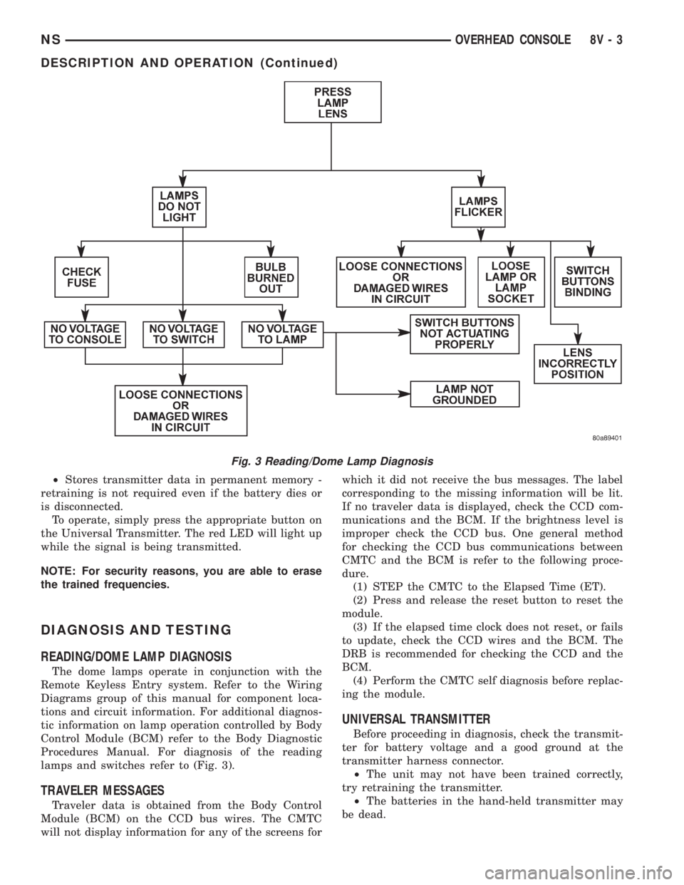
READING/DOME LAMP DIAGNOSIS
The dome lamps operate in conjunction with the
Remote Keyless Entry system. Refer to the Wiring
Diagrams group of this manual for component loca-
tions and circuit information. For additional diagnos-
tic information on lamp operation controlled by Body
Control Module (BCM) refer to the Body Diagnostic
Procedures Manual. For diagnosis of the reading
lamps and switches refer to (Fig. 3).
TRAVELER MESSAGES
Traveler data is obtained from the Body Control
Module (BCM) on the CCD bus wires. The CMTC
will not display information for any of the screens forwhich it did not receive the bus messages. The label
corresponding to the missing information will be lit.
If no traveler data is displayed, check the CCD com-
munications and the BCM. If the brightness level is
improper check the CCD bus. One general method
for checking the CCD bus communications between
CMTC and the BCM is refer to the following proce-
dure.
(1) STEP the CMTC to the Elapsed Time (ET).
(2) Press and release the reset button to reset the
module.
(3) If the elapsed time clock does not reset, or fails
to update, check the CCD wires and the BCM. The
DRB is recommended for checking the CCD and the
BCM.
(4) Perform the CMTC self diagnosis before replac-
ing the module.
UNIVERSAL TRANSMITTER
Before proceeding in diagnosis, check the transmit-
ter for battery voltage and a good ground at the
transmitter harness connector.
²The unit may not have been trained correctly,
try retraining the transmitter.
²The batteries in the hand-held transmitter may
be dead.
Fig. 3 Reading/Dome Lamp Diagnosis
NSOVERHEAD CONSOLE 8V - 3
DESCRIPTION AND OPERATION (Continued)
Page 561 of 1938
WIRING DIAGRAMS
CONTENTS
page page
AIR CONDITIONING-HEATER.......... 8W-42-1
AIRBAG SYSTEM................... 8W-43-1
ANTI-LOCK BRAKES................. 8W-35-1
AUDIO SYSTEM.................... 8W-47-1
BODY CONTROL MODULE............ 8W-45-1
CHARGING SYSTEM................. 8W-20-1
COMPONENT INDEX................. 8W-02-1
CONNECTOR/GROUND LOCATIONS..... 8W-90-1
CONNECTOR PIN-OUTS.............. 8W-80-1
FRONT LIGHTING................... 8W-50-1
FUEL/IGNITION SYSTEM............. 8W-30-1
GENERAL INFORMATION............. 8W-01-1
GROUND DISTRIBUTION............. 8W-15-1
HORN/CIGAR LIGHTER/POWER OUTLET . 8W-41-1
INSTRUMENT CLUSTER.............. 8W-40-1
INTERIOR LIGHTING................. 8W-44-1
JUNCTION BLOCK................... 8W-12-1
MESSAGE CENTER.................. 8W-46-1OVERHEAD CONSOLE................ 8W-49-1
POWER DISTRIBUTION.............. 8W-10-1
POWER DOOR LOCKS............... 8W-61-1
POWER MIRRORS.................. 8W-62-1
POWER SEAT...................... 8W-63-1
POWER WINDOWS.................. 8W-60-1
REAR LIGHTING.................... 8W-51-1
SPLICE INFORMATION............... 8W-70-1
SPLICE LOCATIONS................. 8W-95-1
STARTING SYSTEM................. 8W-21-1
TRAILER TOW...................... 8W-54-1
TRANSMISSION CONTROL SYSTEM.... 8W-31-1
TURN SIGNALS..................... 8W-52-1
VEHICLE SPEED CONTROL........... 8W-33-1
VEHICLE THEFT SECURITY SYSTEM.... 8W-39-1
WINDOW DEFOGGERS............... 8W-48-1
WIPERS........................... 8W-53-1
NS/GSWIRING DIAGRAMS 8W - 1
Page 563 of 1938
8W-01 GENERAL INFORMATION
INDEX
page page
DESCRIPTION AND OPERATION
CIRCUIT FUNCTIONS..................... 4
CIRCUIT INFORMATION................... 4
CONNECTOR INFORMATION............... 7
ELECTROSTATIC DISCHARGE (ESD)
SENSITIVE DEVICES.................... 8
INTRODUCTION......................... 1
NOTES, CAUTIONS, and WARNINGS......... 7
POSITIVE TEMPERATURE COEFFICIENT...... 8
SECTION IDENTIFICATION................. 5
SPLICE LOCATIONS...................... 7
SYMBOLS.............................. 5
TAKE OUTS............................. 8
TERMINOLOGY.......................... 7
DIAGNOSIS AND TESTING
INTERMITTENT AND POOR CONNECTIONS.... 9TROUBLESHOOTING TESTS................ 9
TROUBLESHOOTING TOOLS............... 8
TROUBLESHOOTING WIRING PROBLEMS.... 10
SERVICE PROCEDURES
CONNECTOR AND TERMINAL REPLACEMENT . 12
CONNECTOR REPLACEMENT.............. 11
DIODE REPLACEMENT................... 14
TERMINAL REPLACEMENT................ 13
TERMINAL/CONNECTOR REPAIR- AUGAT
CONNECTORS........................ 12
TERMINAL/CONNECTOR REPAIR-MOLEX
CONNECTORS........................ 11
WIRING REPAIR........................ 10
SPECIAL TOOLS
WIRING/TERMINAL...................... 14
DESCRIPTION AND OPERATION
INTRODUCTION
Chrysler wiring diagrams are designed to provide
information regarding the vehicles wiring content. In
order to effectively use Chrysler wiring diagrams to
diagnose and repair a Chrysler vehicle, it is impor-
tant to understand all of their features and charac-
teristics.
Diagrams are arranged such that the power (B+)
side of the circuit is placed near the top of the page,
and the ground (B-) side of the circuit is placed near
the bottom of the page.
All switches, components, and modules are shown
in the at rest position with the doors closed and the
key removed from the ignition.Components are shown two ways. A solid line
around a component indicates that the component is
complete. A dashed line around a component indi-
cates that the component being shown is not com-
plete. Incomplete components have a reference
number to indicate the page where the component is
shown complete.
It is important to realize that no attempt is made
on the diagrams to represent components and wiring
as they appear on the vehicle. For example, a short
piece of wire is treated the same as a long one. In
addition, switches and other components are shown
as simply as possible, with regard to function only.
NS/GS8W-01 GENERAL INFORMATION 8W - 01 - 1
Page 566 of 1938
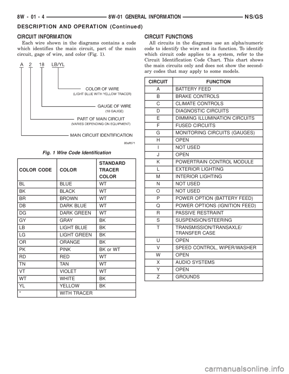
CIRCUIT INFORMATION
Each wire shown in the diagrams contains a code
which identifies the main circuit, part of the main
circuit, gage of wire, and color (Fig. 1).
CIRCUIT FUNCTIONS
All circuits in the diagrams use an alpha/numeric
code to identify the wire and its function. To identify
which circuit code applies to a system, refer to the
Circuit Identification Code Chart. This chart shows
the main circuits only and does not show the second-
ary codes that may apply to some models.
Fig. 1 Wire Code Identification
COLOR CODE COLORSTANDARD
TRACER
COLOR
BL BLUE WT
BK BLACK WT
BR BROWN WT
DB DARK BLUE WT
DG DARK GREEN WT
GY GRAY BK
LB LIGHT BLUE BK
LG LIGHT GREEN BK
OR ORANGE BK
PK PINK BK or WT
RD RED WT
TN TAN WT
VT VIOLET WT
WT WHITE BK
YL YELLOW BK
* WITH TRACER
CIRCUIT FUNCTION
A BATTERY FEED
B BRAKE CONTROLS
C CLIMATE CONTROLS
D DIAGNOSTIC CIRCUITS
E DIMMING ILLUMINATION CIRCUITS
F FUSED CIRCUITS
G MONITORING CIRCUITS (GAUGES)
H OPEN
I NOT USED
J OPEN
K POWERTRAIN CONTROL MODULE
L EXTERIOR LIGHTING
M INTERIOR LIGHTING
N NOT USED
O NOT USED
P POWER OPTION (BATTERY FEED)
Q POWER OPTIONS (IGNITION FEED)
R PASSIVE RESTRAINT
S SUSPENSION/STEERING
T TRANSMISSION/TRANSAXLE/
TRANSFER CASE
U OPEN
V SPEED CONTROL, WIPER/WASHER
W OPEN
X AUDIO SYSTEMS
Y OPEN
Z GROUNDS
8W - 01 - 4 8W-01 GENERAL INFORMATIONNS/GS
DESCRIPTION AND OPERATION (Continued)
Page 567 of 1938

SECTION IDENTIFICATION
The wiring diagrams are grouped into individual
sections. If a component is most likely found in a par-
ticular group, it will be shown complete (all wires,
connectors, and pins) within that group. For exam-
ple, the Auto Shutdown Relay is most likely to be
found in Group 30, so it is shown there complete. It
can, however, be shown partially in another group if
it contains some associated wiring.
SYMBOLS
International symbols are used throughout the wir-
ing diagrams. These symbols are consistent with
those being used around the world.
GROUP TOPIC
8W-01 thru 8W-09 General Information and
Diagram Overview
8W-10 thru 8W-19 Main Sources of Power and
Vehicle Grounding
8W-20 thru 8W-29 Starting and Charging
8W-30 thru 8W-39 Powertrain/Drivetrain
Systems
8W-40 thru 8W-49 Body Electrical items and A/C
8W-50 thru 8W-59 Exterior Lighting, Wipers, and
Trailer Tow
8W-60 thru 8W-69 Power Accessories
8W-70 Splice Information
8W-80 Connector Pin Outs
8W-90 Connector Locations
(including grounds)
8W-95 Splice Locations
NS/GS8W-01 GENERAL INFORMATION 8W - 01 - 5
DESCRIPTION AND OPERATION (Continued)
Page 568 of 1938
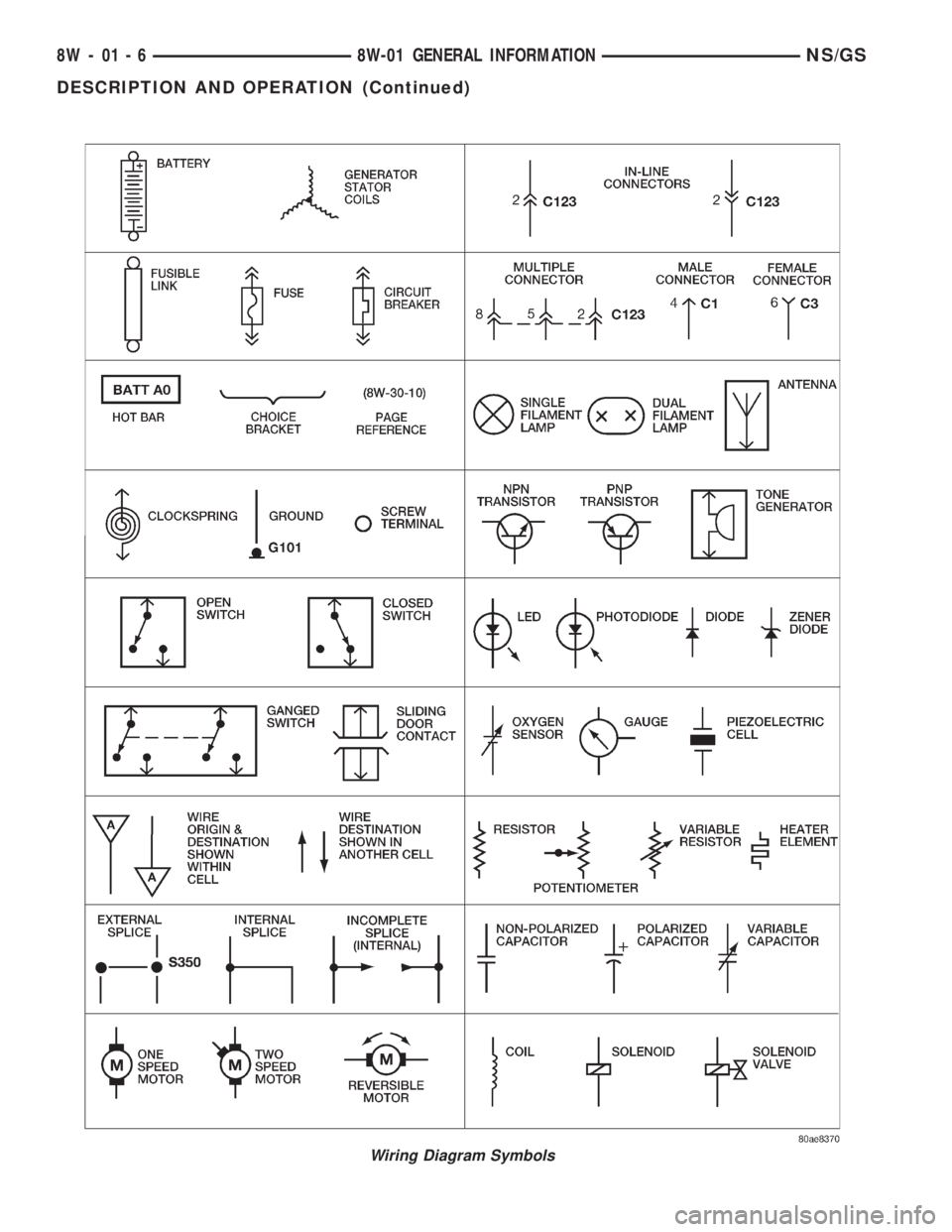
Wiring Diagram Symbols
8W - 01 - 6 8W-01 GENERAL INFORMATIONNS/GS
DESCRIPTION AND OPERATION (Continued)
Page 569 of 1938
TERMINOLOGY
This a list of terms with there definitions used in
the wiring diagrams.
Built-Up-Export.........Vehicles Built For Sale In
Markets Other Than North America
Except-Built-Up-Export.....Vehicles Built For Sale
In North America
LHD..................Left Hand Drive Vehicles
RHD.................Right Hand Drive Vehicles
ATX . . . .Automatic Transmission-Front Wheel Drive
MTX......Manual Transmission-Front Wheel Drive
AT......Automatic Transmission-Rear Wheel Drive
MT .......Manual Transmission-Rear Wheel Drive
SOHC.............Single Over Head Cam Engine
DOHC.............Dual Over Head Cam Engine
CONNECTOR INFORMATION
CAUTION: Not all connectors are serviced. Some
connectors are serviced only with a harness. A typ-
ical example might be the Supplemental Restraint
System connectors. Always check parts availability
before attempting a repair.
IDENTIFICATION
In-line connectors are identified by a number, as
follows:
²In-line connectors located on theengine com-
partment harnessareC100series numbers.
²Connectors located on theinstrument panel
harnessareC200series numbers.
²Connectors located on thebody harnessare
C300series numbers.
²Jumper harness connectorsareC400series
numbers.
²Grounds and ground connectorsare identi-
fied with aªGºand follow the same series number-
ing as the in-line connector.
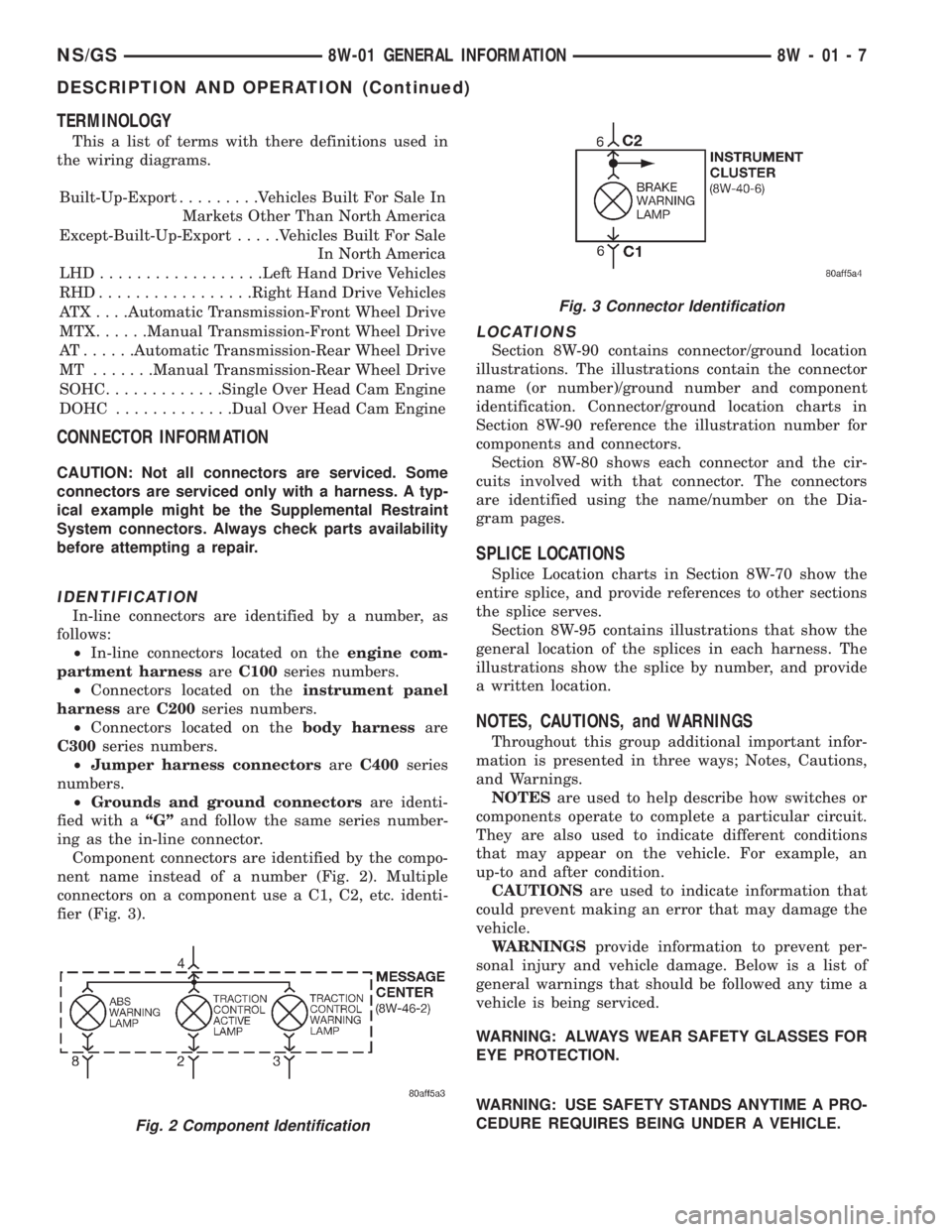
Component connectors are identified by the compo-
nent name instead of a number (Fig. 2). Multiple
connectors on a component use a C1, C2, etc. identi-
fier (Fig. 3).
LOCATIONS
Section 8W-90 contains connector/ground location
illustrations. The illustrations contain the connector
name (or number)/ground number and component
identification. Connector/ground location charts in
Section 8W-90 reference the illustration number for
components and connectors.
Section 8W-80 shows each connector and the cir-
cuits involved with that connector. The connectors
are identified using the name/number on the Dia-
gram pages.
SPLICE LOCATIONS
Splice Location charts in Section 8W-70 show the
entire splice, and provide references to other sections
the splice serves.
Section 8W-95 contains illustrations that show the
general location of the splices in each harness. The
illustrations show the splice by number, and provide
a written location.
NOTES, CAUTIONS, and WARNINGS
Throughout this group additional important infor-
mation is presented in three ways; Notes, Cautions,
and Warnings.
NOTESare used to help describe how switches or
components operate to complete a particular circuit.
They are also used to indicate different conditions
that may appear on the vehicle. For example, an
up-to and after condition.
CAUTIONSare used to indicate information that
could prevent making an error that may damage the
vehicle.
WARNINGSprovide information to prevent per-
sonal injury and vehicle damage. Below is a list of
general warnings that should be followed any time a
vehicle is being serviced.
WARNING: ALWAYS WEAR SAFETY GLASSES FOR
EYE PROTECTION.
WARNING: USE SAFETY STANDS ANYTIME A PRO-
CEDURE REQUIRES BEING UNDER A VEHICLE.
Fig. 2 Component Identification
Fig. 3 Connector Identification
NS/GS8W-01 GENERAL INFORMATION 8W - 01 - 7
DESCRIPTION AND OPERATION (Continued)