set clock CHRYSLER VOYAGER 1996 User Guide
[x] Cancel search | Manufacturer: CHRYSLER, Model Year: 1996, Model line: VOYAGER, Model: CHRYSLER VOYAGER 1996Pages: 1938, PDF Size: 55.84 MB
Page 1089 of 1938

CAUTION: If timing belt was damaged due to incor-
rect tracking (alignment), the belt tensioner assem-
bly must be replace. Refer to Timing Belt Tensioner
Assembly Removal and Installation procedure out-
lined in this section.
INSTALLATION
(1) Set crankshaft sprocket to TDC by aligning
the sprocket with the arrow on the oil pump housing.
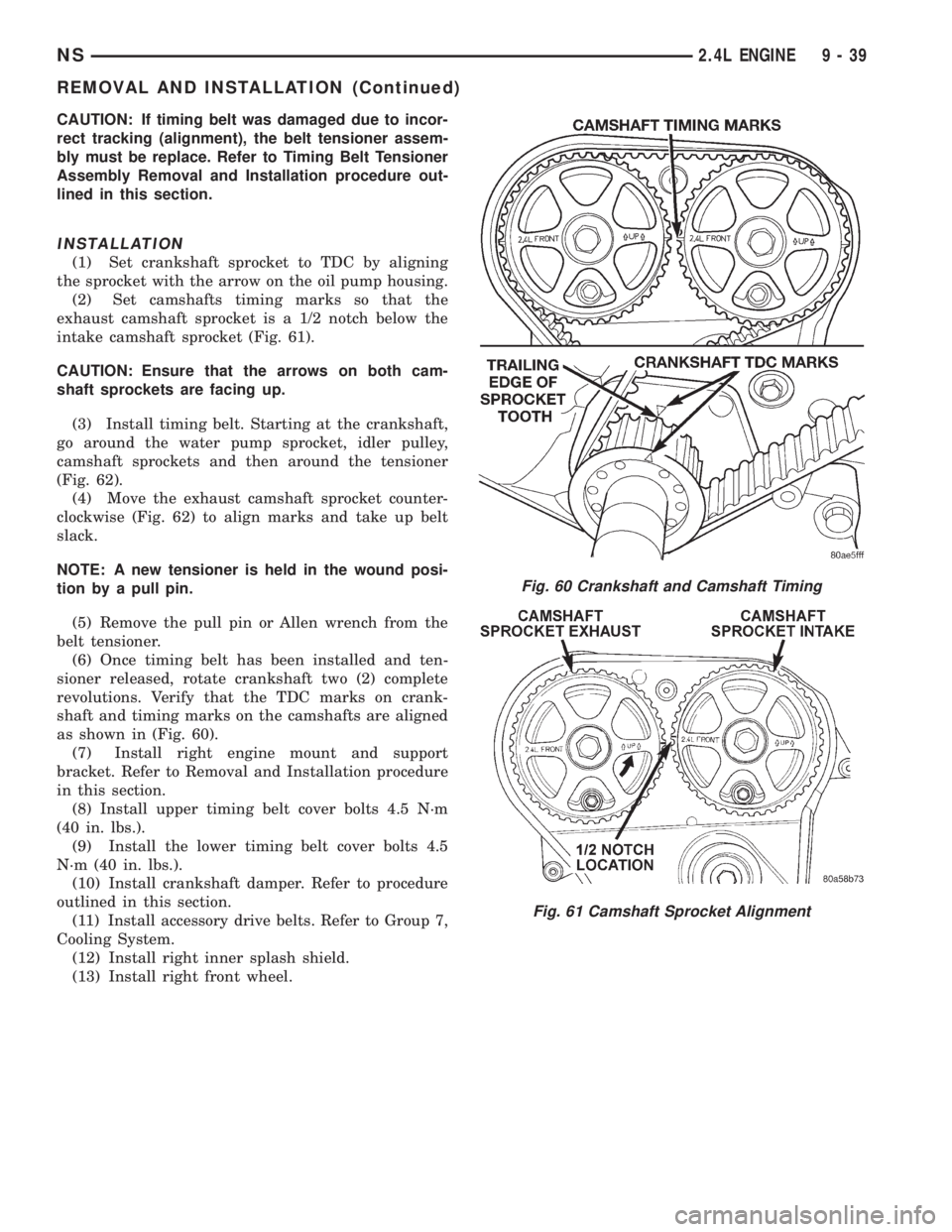
(2) Set camshafts timing marks so that the
exhaust camshaft sprocket is a 1/2 notch below the
intake camshaft sprocket (Fig. 61).
CAUTION: Ensure that the arrows on both cam-
shaft sprockets are facing up.
(3) Install timing belt. Starting at the crankshaft,
go around the water pump sprocket, idler pulley,
camshaft sprockets and then around the tensioner
(Fig. 62).
(4) Move the exhaust camshaft sprocket counter-
clockwise (Fig. 62) to align marks and take up belt
slack.
NOTE: A new tensioner is held in the wound posi-
tion by a pull pin.
(5) Remove the pull pin or Allen wrench from the
belt tensioner.
(6) Once timing belt has been installed and ten-
sioner released, rotate crankshaft two (2) complete
revolutions. Verify that the TDC marks on crank-
shaft and timing marks on the camshafts are aligned
as shown in (Fig. 60).
(7) Install right engine mount and support
bracket. Refer to Removal and Installation procedure
in this section.
(8) Install upper timing belt cover bolts 4.5 N´m
(40 in. lbs.).
(9) Install the lower timing belt cover bolts 4.5
N´m (40 in. lbs.).
(10) Install crankshaft damper. Refer to procedure
outlined in this section.
(11) Install accessory drive belts. Refer to Group 7,
Cooling System.
(12) Install right inner splash shield.
(13) Install right front wheel.
Fig. 60 Crankshaft and Camshaft Timing
Fig. 61 Camshaft Sprocket Alignment
NS2.4L ENGINE 9 - 39
REMOVAL AND INSTALLATION (Continued)
Page 1194 of 1938

(14) Install crankshaft damper using M12-1.75 x
150 mm bolt, washer, thrust bearing and nut from
Special Tool 6792. Install crankshaft damper bolt and
tighten to 142 N´m (105 ft. lbs.) (Fig. 39).
(15) Install accessory drive belts. Refer to Group 7,
Cooling System Accessory Drive section for proce-
dure.
(16) Perform camshaft and crankshaft timing
relearn. Refer to Group 25, Emission Control Sys-
tems for procedure.
TIMING BELTÐw/AUTO TENSIONERÐIF
EQUIPPED
CHECKING BELT TIMINGÐCOVER INSTALLED
²Remove number one spark plug.
²Using a dial indicator, set number one cylinder
to TDC on the compression stroke.
²Remove the access plug from the outer timing
belt cover (Fig. 28).
²Check the timing mark on the camshaft
sprocket, it should align with the arrow on the rear
belt cover (Fig. 29).
REMOVALÐTIMING BELT
(1) Remove accessory drive belts. Refer to Group 7,
Cooling System for procedure outlined in that sec-
tion.
(2) Raise vehicle on a hoist and remove right inner
splash shield (Fig. 42).
(3) Remove crankshaft damper bolt. Remove
damper using the large side of Special Tool 1026 and
insert 6827-A (Fig. 30).
(4) Lower vehicle and place a jack under engine.
(5) Remove right engine mount. Refer to procedure
outlined in this section.
(6) Remove right engine mount bracket (Fig. 44).
(7) Remove front timing belt cover (Fig. 31).CAUTION: Align camshaft and crankshaft timing
marks before removing the timing belt by rotating
the engine with the crankshaft.
(8) Inserta8mmAllen wrench into the belt ten-
sioner. Before rotating the tensioner insert the long
end of a 1/8º or 3 mm Allen wrench into the pin hole
on the front of the tensioner (Fig. 33). Rotate the ten-
sioner counterclockwise with the Allen wrench, while
pushing in lightly on the 1/8 in. or 3 mm Allen
wrench, until it slides into the locking hole.
(9) Remove timing belt.
CAUTION: Do not rotate the camshafts once the
timing belt has been removed or damage to valve
components may occur.
CAMSHAFT AND CRANKSHAFT TIMING PROCEDURE AND
BELT INSTALLATION ÐSOHC ENGINE
(1) Set crankshaft sprocket to TDC by aligning the
sprocket with the arrow on the oil pump housing,
then back off to 3 notches before TDC (Fig. 35).
(2) Set camshaft to TDC by aligning mark on
sprocket with the arrow on the rear of timing belt
cover (Fig. 36).
(3) Move crankshaft to 1/2 mark before TDC (Fig.
37) for belt installation.
(4) Install timing belt. Starting at the crankshaft,
go around the water pump sprocket and then around
the camshaft sprocket.
(5) Move crankshaft sprocket to TDC to take up
belt slack.
(6) Remove the pin or 1/8º or 3 mm Allen wrench
from belt tensioner.
(7) Rotate crankshaft 2 revolutions and check the
alignment of the timing marks (Fig. 50).
(8) Install front half of timing cover.
(9) Install engine mount bracket.
(10) Install Right engine mount. Refer to proce-
dure outlined in this section.
(11) Remove jack from under engine.
(12) Install crankshaft damper using M12-1.75 x
150 mm bolt, washer, thrust bearing and nut from
Special Tool 6792. Install crankshaft damper bolt and
tighten to 142 N´m (105 ft. lbs.) (Fig. 39).
(13) Install accessory drive belts. Refer to Group 7,
Cooling System Accessory Drive section for proce-
dure.
(14) Raise vehicle on hoist and install right inner
splash shield.
(15) Perform camshaft and crankshaft timing
relearn procedure as follows:
²Connect the DRB scan tool to the data link
(diagnostic) connector. This connector is located in
the passenger compartment; at the lower edge of
instrument panel; near the steering column.
Fig. 39 Crankshaft DamperÐInstallation
9 - 16 ENGINENS/GS
REMOVAL AND INSTALLATION (Continued)
Page 1388 of 1938

(8) Disconnect the main engine wiring harness
from the glow plugs.
(9) Disconnect the four high±pressure fuel lines
from the fuel injection pump. Also disconnect fuel
lines at the fuel injectors. For procedures, refer to
High±Pressure Fuel Lines in this group. Place a rag
beneath the fittings to catch excess fuel.
(10) Remove plug from timing gear cover.
(11) The ªTop Dead Centerº (TDC) compression fir-
ing stroke must be determined as follows:
(a) Remove the valve cover, refer to Group 9,
Valve Cover Removal/Installation.
(b) Remove the right front tire and splash
shield. Using a socket attached to the end of crank-
shaft, rotate the engine (counterÐclockwise as
viewed from front).
(c) Rotate the engine until cylinder #4 rockers
are in between movement.
(d) Remove rocker arm assembly.
(e) Remove valve spring and keepers.CAU-
TION: When the piston is at TDC there is only
2 mm (.080 thousand) clearance between the
valve and piston.
(f) Let the valve set on top of piston. Install a
dial indicator to the top of the valve stem.
(g) Rotate engine back and forth to find the TDC
position with the indicator on the valve stem. Mark
the damper and timing cover for TDC.
NOTE: On later model 1997 engines, a hole in the
bottom of the clutch housing can be lined up with a
hole in the flywheel, allowing the engine to be held
at TDC with a special alignment tool, part # VM1035.(12) Remove injection pump drive gear nut (Fig.
41) and washer.CAUTION: Be very careful not to
drop the washer into the timing gear cover.
(13) A special 3±piece gear removal tool set
VM.1003 (Fig. 42) must be used to remove the injec-
tion pump drive gear from the pump shaft.
(a) Thread the adapter (Fig. 43) into the timing
cover.
(b) Thread the gear puller into the injection
pump drive gear (Fig. 43). This tool is also used to
hold the gear in synchronization during pump
removal.
(c) Remove the three injection pump±to±gear
cover mounting nuts (Fig. 44).CAUTION: This
step must be done to prevent breakage of the
Fig. 40 Engine Coolant Temperature Sensor
Fig. 41 Removing Pump Drive Gear Nut
Fig. 42 Pump Gear Tools
14 - 20 FUEL SYSTEMÐ2.5L DIESEL ENGINE/2.0L GAS ENGINENS/GS
REMOVAL AND INSTALLATION (Continued)
Page 1526 of 1938

(3) Back off adjusting screw the number of turns
listed in Specifications. Hold adjusting screw in this
position and tighten locknut to 47 N´m (35ft. lbs.)
LOW/REVERSE BAND (REAR)
To adjust low-reverse band, proceed as follows:
(1) Loosen and back off locknut approximately 5
turns.
(2) Using an inch-pound torque wrench, tighten
adjusting screw to 5 N´m (41 in. lbs.) true torque.
(3) Back off adjusting screw the number of turns
listed under Specifications. This chart is located at
the rear of this section.
(4) Tighten locknut to 14 N´m (10 ft. lbs.).
HYDRAULIC CONTROL PRESSURE ADJUSTMENTS
LINE PRESSURE
An incorrect throttle pressure setting will cause
incorrect line pressure readings even though line
pressure adjustment is correct. Always inspect and
correct throttle pressure adjustment before adjusting
the line pressure.
The approximate adjustment for line pressure is
1-5/16 inches, measured from valve body to inner
edge of adjusting nut. However, due to manufactur-
ing tolerances, the adjustment can be varied to
obtain specified line pressure.
The adjusting screw may be turned with an Allen
wrench. One complete turn of adjusting screw
changes closed throttle line pressure approximately
1-2/3 psi. Turning adjusting screw counterclockwise
increases pressure, and clockwise decreases pressure.
THROTTLE PRESSURE
Throttle pressures cannot be tested accurately;
therefore, the adjustment should be measured if a
malfunction is evident.
(1) Insert gauge pin of Tool C-3763 between the
throttle lever cam and kickdown valve.
(2) By pushing in on tool, compress kickdown
valve against its spring so throttle valve is com-
pletely bottomed inside the valve body.
(3) While compressing spring, turn throttle lever
stop screw with adapter C-4553. Turn until head of
screw touches throttle lever tang, with throttle lever
cam touching tool and throttle valve bottomed. Be
sure adjustment is made with spring fully com-
pressed and valve bottomed in the valve body.
BEARING ADJUSTMENT PROCEDURES
(1) Take extreme care when removing and install-
ing bearing cups and cones.Use only an arbor
press for installation, as a hammer may not
properly align the bearing cup or cone.Burrs or
nicks on the bearing seat will give a false end play
reading, while gauging for proper shims. Improperlyseated bearing cup and cones are subject to low-mile-
age failure.
(2) Bearing cups and cones should be replaced if
they show signs of pitting or heat distress.
(3) If distress is seen on either the cup or bearing
rollers, both cup and cone must be replaced.
NOTE: Bearing end play and drag torque specifica-
tions must be maintained to avoid premature bear-
ing failures.
(4) Used (original) bearing may lose up to 50 per-
cent of the original drag torque after break-in.
NOTE: All bearing adjustments must be made with
no other component interference or gear inter-
mesh, except the transfer gear bearing.
(5) Refer to the conversion chart in specifications
to convert inches to millimeter measurements. Refer
to bearing shim chart for proper shim thicknesses.
OUTPUT SHAFT BEARING
(1) With output shaft gear removed, install a 13.65
mm (.537 inch) and a 1.34 mm (.053 inch) gauging
shims on the planetary rear annulus gear hub using
grease to hold the shims in place. The 13.65 mm
shim has a larger inside diameter and must be
installed over the output shaft first. The 1.34 mm
shim pilots on the output shaft.
(2) Install output shaft gear and bearing assembly,
torque to 271 N´m (200 ft. lbs.).
(3) To measure bearing end play:
(4) Attach Tool L-4432 to the output shaft gear.
(5) Mount a steel ball with grease into the end of
the output shaft.
(6) Push and pull the gear while rotating back and
forth to insure seating of the bearing rollers.
(7) Using a dial indicator, mounted to the tran-
saxle case, measure output shaft end play.
(8) Once bearing end play has been determined,
refer to the output shaft bearing shim chart.
(9) The 12.65 mm (.498 inch), 13.15 mm (.518
inch) or 13.65 mm (.537 inch) shims are always
installed first.These shims have lubrication slots
which are necessary for proper bearing lubrica-
tion.
(10) Shims thinner than 12.65 mm listed in the
chart are common to both the transfer shaft and out-
put shaft bearings.
(11) Use Tool L-4434 to remove the retaining nut
and washer. To remove the output shaft gear use Tool
L-4407.
(12) Remove the two gauging shims and install the
proper shim combination, making sure to install the
12.65, 13.15, or 13.65 mm shim first. Use grease to
21 - 52 TRANSAXLE AND POWER TRANSFER UNITNS
ADJUSTMENTS (Continued)
Page 1565 of 1938

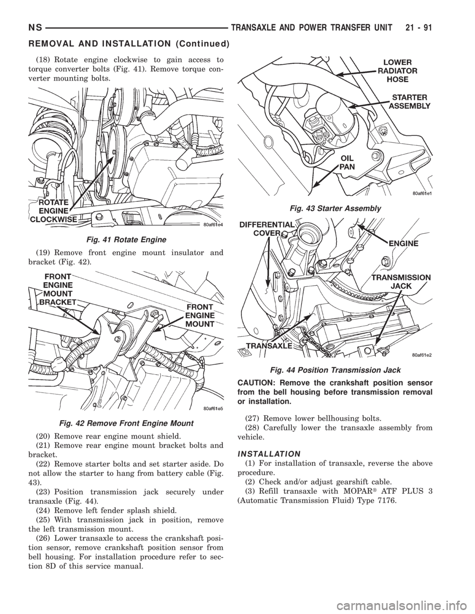
(18) Rotate engine clockwise to gain access to
torque converter bolts (Fig. 41). Remove torque con-
verter mounting bolts.
(19) Remove front engine mount insulator and
bracket (Fig. 42).
(20) Remove rear engine mount shield.
(21) Remove rear engine mount bracket bolts and
bracket.
(22) Remove starter bolts and set starter aside. Do
not allow the starter to hang from battery cable (Fig.
43).
(23) Position transmission jack securely under
transaxle (Fig. 44).
(24) Remove left fender splash shield.
(25) With transmission jack in position, remove
the left transmission mount.
(26) Lower transaxle to access the crankshaft posi-
tion sensor, remove crankshaft position sensor from
bell housing. For installation procedure refer to sec-
tion 8D of this service manual.CAUTION: Remove the crankshaft position sensor
from the bell housing before transmission removal
or installation.
(27) Remove lower bellhousing bolts.
(28) Carefully lower the transaxle assembly from
vehicle.
INSTALLATION
(1) For installation of transaxle, reverse the above
procedure.
(2) Check and/or adjust gearshift cable.
(3) Refill transaxle with MOPARtATF PLUS 3
(Automatic Transmission Fluid) Type 7176.
Fig. 41 Rotate Engine
Fig. 42 Remove Front Engine Mount
Fig. 43 Starter Assembly
Fig. 44 Position Transmission Jack
NSTRANSAXLE AND POWER TRANSFER UNIT 21 - 91
REMOVAL AND INSTALLATION (Continued)
Page 1699 of 1938

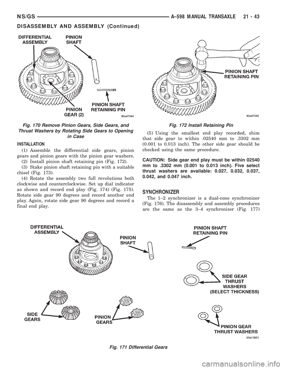
INSTALLATION
(1) Assemble the differential side gears, pinion
gears and pinion gears with the pinion gear washers.
(2) Install pinion shaft retaining pin (Fig. 172).
(3) Stake pinion shaft retaining pin with a suitable
chisel (Fig. 173).
(4) Rotate the assembly two full revolutions both
clockwise and counterclockwise. Set up dial indicator
as shown and record end play (Fig. 174) (Fig. 175).
Rotate side gear 90 degrees and record another end
play. Again, rotate side gear 90 degrees and record a
final end play.(5) Using the smallest end play recorded, shim
that side gear to within .02540 mm to .3302 mm
(0.001 to 0.013 inch). The other side gear should be
checked using the same procedure.
CAUTION: Side gear end play must be within 02540
mm to .3302 mm (0.001 to 0.013 inch). Five select
thrust washers are available: 0.027, 0.032, 0.037,
0.042, and 0.047 inch.
SYNCHRONIZER
The 1±2 synchronizer is a dual-cone synchronizer
(Fig. 176). The disassembly and assembly procedures
are the same as the 3±4 synchronizer (Fig. 177)
Fig. 171 Differential Gears
Fig. 170 Remove Pinion Gears, Side Gears, and
Thrust Washers by Rotating Side Gears to Opening
in CaseFig. 172 Install Retaining Pin
NS/GSA±598 MANUAL TRANSAXLE 21 - 43
DISASSEMBLY AND ASSEMBLY (Continued)
Page 1914 of 1938

The primary components within the assembly are:
A three port solenoid that activates both of the func-
tions listed above; a pump which contains a switch,
two check valves and a spring/diaphragm, a canister
vent valve (CVV) seal which contains a spring loaded
vent seal valve.
Immediately after a cold start, between predeter-
mined temperature thresholds limits, the three port
solenoid is briefly energized. This initializes the
pump by drawing air into the pump cavity and also
closes the vent seal. During non test conditions the
vent seal is held open by the pump diaphragm
assembly which pushes it open at the full travel posi-
tion. The vent seal will remain closed while the
pump is cycling due to the reed switch triggering of
the three port solenoid that prevents the diaphragm
assembly from reaching full travel. After the brief
initialization period, the solenoid is de-energized
allowing atmospheric pressure to enter the pump
cavity, thus permitting the spring to drive the dia-
phragm which forces air out of the pump cavity and
into the vent system. When the solenoid is energized
and de energized, the cycle is repeated creating flow
in typical diaphragm pump fashion. The pump is con-
trolled in 2 modes:
Pump Mode:The pump is cycled at a fixed rate to
achieve a rapid pressure build in order to shorten the
overall test length.
Test Mode:The solenoid is energized with a fixed
duration pulse. Subsequent fixed pulses occur when
the diaphragm reaches the Switch closure point.
The spring in the pump is set so that the system
will achieve an equalized pressure of about 7.5º H20.
The cycle rate of pump strokes is quite rapid as the
system begins to pump up to this pressure. As the
pressure increases, the cycle rate starts to drop off. If
there is no leak in the system, the pump would even-
tually stop pumping at the equalized pressure. If
there is a leak, it will continue to pump at a rate rep-
resentative of the flow characteristic of the size of the
leak. From this information we can determine if the
leak is larger than the required detection limit (cur-
rently set at .020º orifice by CARB). If a leak is
revealed during the leak test portion of the test, the
test is terminated at the end of the test mode and no
further system checks will be performed.
After passing the leak detection phase of the test,
system pressure is maintained by turning on the
LDP's solenoid until the purge system is activated.
Purge activation in effect creates a leak. The cycle
rate is again interrogated and when it increases due
to the flow through the purge system, the leak check
portion of the diagnostic is complete.
The canister vent valve will unseal the system
after completion of the test sequence as the pumpdiaphragm assembly moves to the full travel position.
Evaporative system functionality will be verified by
using the stricter evap purge flow monitor. At an
appropriate warm idle the LDP will be energized to
seal the canister vent. The purge flow will be clocked
up from some small value in an attempt to see a
shift in the 02 control system. If fuel vapor, indicated
by a shift in the 02 control, is present the test is
passed. If not, it is assumed that the purge system is
not functioning in some respect. The LDP is again
turned off and the test is ended.
TRIP DEFINITION
A ªTripº means vehicle operation (following an
engine-off period) of duration and driving mode such
that all components and systems are monitored at
least once by the diagnostic system. The monitors
must successfully pass before the PCM can verify
that a previously malfunctioning component is meet-
ing the normal operating conditions of that compo-
nent. For misfire or fuel system malfunction, the
MIL may be extinguished if the fault does not recur
when monitored during three subsequent sequential
driving cycles in which conditions are similar to
those under which the malfunction was first deter-
mined.
Anytime the MIL is illuminated, a DTC is stored.
The DTC can self erase only when the MIL has been
extinguished. Once the MIL is extinguished, the
PCM must pass the diagnostic test for the most
recent DTC for 40 warm-up cycles (80 warm-up
cycles for the Fuel System Monitor and the Misfire
Monitor). A warm-up cycle can best be described by
the following:
²The engine must be running
²A rise of 40ÉF in engine temperature must occur
from the time when the engine was started
²Engine coolant temperature must reach at least
160ÉF
²A ªdriving cycleº that consists of engine start up
and engine shut off.
Once the above conditions occur, the PCM is con-
sidered to have passed a warm-up cycle. Due to the
conditions required to extinguish the MIL and erase
the DTC, it is most important that after a repair has
been made, all DTC's be erased and the repair veri-
fied.
COMPONENT MONITORS
There are several components that will affect vehi-
cle emissions if they malfunction. If one of these com-
ponents malfunctions the Malfunction Indicator
Lamp (Check Engine) will illuminate.
Some of the component monitors are checking for
proper operation of the part. Electrically operated
25 - 10 EMISSION CONTROL SYSTEMSNS
DESCRIPTION AND OPERATION (Continued)