stop start CHRYSLER VOYAGER 1996 User Guide
[x] Cancel search | Manufacturer: CHRYSLER, Model Year: 1996, Model line: VOYAGER, Model: CHRYSLER VOYAGER 1996Pages: 1938, PDF Size: 55.84 MB
Page 617 of 1938
8W-12 JUNCTION BLOCK
Component PageA/C Compressor Clutch Relay..............8W-12-13
A/C Heater Control.................8W-12-9, 12, 23
Airbag Control Module...................8W-12-13
Ash Receiver Lamp...................8W-12-19, 23
Automatic Day/Night Mirror................8W-12-9
Back-Up Switch........................8W-12-12
Body Control Module........8W-12-8, 9, 14, 15, 17, 18,
19, 20, 22, 23, 24, 26
Brake Pressure Switch...................8W-12-17
Cigar/Accessory Relay....................8W-12-16
Clutch Interlock Switch..................8W-12-16
Clutch Interlock Switch Jumper............8W-12-16
Combination Flasher/DRL Module . . .8W-12-12, 17, 18, 19
Controller Anti-Lock Brake................8W-12-12
Courtesy Lamp Relay....................8W-12-22
CS01...............................8W-12-22
CS02...............................8W-12-21
CS04................................8W-12-9
CS1................................8W-12-22
Data Link Connector....................8W-12-20
Door Lock Relay.....................8W-12-15, 19
Door Unlock Relay...................8W-12-14, 19
Driver Door Courtesy Lamp...............8W-12-22
Driver Door Lock Motor................8W-12-14, 15
Driver Door Lock Switch..................8W-12-23
Driver Door Unlock Relay..............8W-12-14, 19
Driver Heated Seat Switch................8W-12-12
Driver Power Mirror..................8W-12-10, 26
Driver Power Window Switch............8W-12-16, 23
EGR Solenoid.........................8W-12-13
Electric Wiper De-Icer...................8W-12-11
Engine Starter Motor Relay...............8W-12-16
ES07...............................8W-12-13
ES29...............................8W-12-13
Evap Leak Detection Pump................8W-12-13
Fog Lamp Relay.......................8W-12-25
Front Blower Motor Relay.................8W-12-12
Front Cigar Lighter/Power Outlet...........8W-12-23
Front Reading Lamps/Switch..............8W-12-21
Front Washer Motor................8W-12-16, 23, 24
Front Wiper Switch................8W-12-16, 23, 24
Fuel Heater Relay......................8W-12-13
Fuel Pump Relay.......................8W-12-13
Fuse 1 (JB)............................8W-12-8
Fuse 2 (JB).........................8W-12-9, 20
Fuse 2 (PDC)..........................8W-12-13
Fuse 3 (JB)............................8W-12-8
Fuse 4 (JB)............................8W-12-8
Fuse 5 (JB).........................8W-12-8, 24
Fuse 6 (JB)............................8W-12-9
Fuse 6 (PDC)..........................8W-12-25
Fuse 7 (JB)...........................8W-12-10
Fuse 8 (JB)...........................8W-12-11
Fuse 9 (JB)...........................8W-12-11
Fuse 10 (JB)..........................8W-12-16
Fuse 11 (JB)..........................8W-12-11
Fuse 12 (JB)..........................8W-12-12
Fuse 18 (PDC).........................8W-12-26
Fuse 22 (PDC).......................8W-12-8, 24
G300..........................8W-12-11, 19, 26
Glove Box Lamp.......................8W-12-21
Headlamp Dimmer Switch..............8W-12-18, 25
Headlamp Switch.............8W-12-8, 19, 22, 23, 25
Headlamp Washer......................8W-12-24
Horn Relay...........................8W-12-17
HS2................................8W-12-12
HS4................................8W-12-12Component PageIgnition Switch...................8W-12-17, 19, 20
Instrument Cluster..............8W-12-9, 19, 20, 23
Junction Block......8W-12-2, 8, 9, 10, 11, 12, 13, 14, 15,
16, 17, 18, 19, 20, 21, 22, 23, 24, 25, 26
Key-In Halo Lamp.................8W-12-19, 22, 26
Left Combination Relay..................8W-12-18
Left Fog Lamp.......................8W-12-8, 25
Left Front Park/Turn Signal Lamp.........8W-12-8, 18
Left Liftgate Flood Lamp.................8W-12-22
Left Low Headlamp.....................8W-12-25
Left Rear Lamp Assembly...............8W-12-8, 18
Left Rear Sliding Door Contact...........8W-12-14, 15
Left Repeater Lamp.....................8W-12-18
Left Stop/Turn Signal Relay...............8W-12-18
License Lamp..........................8W-12-8
Liftgate Lock Motor..................8W-12-14, 15
Low Beam Relay.......................8W-12-25
Message Center..............8W-12-9, 17, 18, 19, 20
Name Brand Speaker Relay.............8W-12-11, 19
Overhead Console.......................8W-12-9
Park Brake Switch......................8W-12-17
Park Lamp Relay.....................8W-12-8, 24
Passenger Door Courtesy Lamp.............8W-12-22
Passenger Door Lock Motor.............8W-12-14, 15
Passenger Door Lock Switch...............8W-12-23
Passenger Heated Seat Switch..............8W-12-12
Passenger Power Mirror...............8W-12-10, 26
Passenger Power Window Switch.........8W-12-16, 23
Power Distribution Center.........8W-8,12-12, 13, 16,
17, 24, 25, 26
Power Folding Mirror Switch............8W-12-19, 26
Power Mirror Fold Relay..................8W-12-26
Power Mirror Switch...............8W-12-19, 21, 23
Power Mirror Unfold Relay................8W-12-26
Powertrain Control Module................8W-12-13
PTC 1 (JB)...........................8W-12-13
PTC 3 (JB)......................8W-12-14, 15, 24
PTC 7 (JB).........................8W-12-16, 24
PTC 8 (JB)...........................8W-12-16
PTC 9 (JB)...........................8W-12-16
Radio..........................8W-12-11, 20, 23
Radio Choke..........................8W-12-11
Rear A/C Heater Unit....................8W-12-11
Rear Blower Front Control Switch...........8W-12-23
Rear Blower Rear Control Switch...........8W-12-23
Rear Washer Motor.....................8W-12-16
Rear Window Defogger...................8W-12-10
Rear Window Defogger Relay............8W-12-10, 12
Rear Wiper Motor.......................8W-12-9
Remote Keyless Entry Module..............8W-12-20
Right Combination Relay.................8W-12-18
Right Fog Lamp......................8W-12-8, 25
Right Front Park/Turn Signal Lamp........8W-12-8, 18
Right Liftgate Flood Lamp................8W-12-22
Right Rear Lamp Assembly..............8W-12-8, 18
Right Rear Sliding Door Contact..........8W-12-14, 15
Right Repeater Lamp....................8W-12-18
Right Stop/Turn Signal Relay..............8W-12-18
Sentry Key Immobilizer Module..........8W-12-13, 21
Stop Lamp Switch......................8W-12-19
Traction Control Switch................8W-12-19, 23
Trailer Tow Connector....................8W-12-8
Transmission Control Module.............8W-12-9, 16
Transmission Range Sensor................8W-12-12
Turn Signal/Hazard Switch................8W-12-17
Universal Garage Door Opener.............8W-12-23
Washer Module.................8W-12-8, 15, 16, 23
NS/GS8W - 12 JUNCTION BLOCK 8W - 12 - 1
Page 665 of 1938
8W-30 FUEL/IGNITION SYSTEM
Component Page
A/C Compressor Clutch Relay................8W-30-5, 37
A/C Heater Control....................8W-30-5, 32, 37
A/C Pressure Transducer.............8W-30-10, 16, 24, 38
Accelerator Pedal Position Sensor...............8W-30-38
Airbag Control Module....................8W-30-4, 31
All Wheel Drive Solenoid....................8W-30-20
Automatic Shut Down Relay . . .8W-30-2, 7, 8, 9, 14, 15, 21, 22, 23
AW4B13...............................8W-30-6
AW4B13..............................8W-30-20
AWS1................................8W-30-20
AWS2................................8W-30-20
Back-Up Switch........................8W-30-6, 20
Battery..........................8W-30-2, 3, 29, 32
Body Control Module.............8W-30-4, 6, 20, 31, 36, 39
BS01................................8W-30-39
BS02...............................8W-30-6, 20
BS05...............................8W-30-4, 31
BS06...............................8W-30-4, 31
BS30................................8W-30-36
BS31..............................8W-30-28, 35
BS32................................8W-30-33
BS33................................8W-30-28
BS34..........................8W-30-33, 34, 36, 38
BS40................................8W-30-35
BS41................................8W-30-35
Camshaft Position Sensor..............8W-30-8, 14, 22, 24
Clockspring...........................8W-30-5, 39
Clutch Switch...........................8W-30-39
Compass/Mini-Trip Computer.................8W-30-31
Control Sleeve Sensor......................8W-30-34
Controller Anti-Lock Brake.................8W-30-4, 31
Crank Case Heater........................8W-30-29
Crankshaft Position Sensor...............8W-30-8, 14, 22
Data Link Connector.................8W-30-3, 4, 30, 31
Diesel Power Relay.................8W-30-28, 29, 32, 33
Downstream Heated Oxygen Sensor............8W-30-7, 21
EGR Solenoid.......................8W-30-18, 20, 29
Engine Coolant Temperature Sensor......8W-30-10, 16, 24, 36
Engine Speed Sensor.......................8W-30-35
Engine Starter Motor Relay...............8W-30-6, 20, 28
ES01................................8W-30-29
ES02.............8W-30-8, 10, 11, 14, 16, 17, 22, 24, 25, 29
ES03.....................8W-30-10, 11, 16, 17, 24, 25
ES05...................8W-30-14, 19, 22, 25, 33, 34, 36
ES06..........................8W-30-28, 29, 32, 33
ES07..........................8W-30-2, 18, 20, 26
ES08............................8W-30-17, 19, 25
ES09................................8W-30-37
ES11................................8W-30-2, 3
ES12.................8W-30-2, 7, 8, 9, 14, 15, 21, 22, 23
ES13.................................8W-30-4
ES14.................................8W-30-4
ES17........................8W-30-8, 11, 14, 17, 22
ES18...............................8W-30-7, 21
ES21..................8W-30-7, 8, 10, 11, 14, 16, 17, 24
ES24.................................8W-30-3
ES26................................8W-30-32
ES28................................8W-30-32
ES29................................8W-30-32
ES30................................8W-30-35
ES31................................8W-30-35
ES37................................8W-30-32
ES40................................8W-30-29
ES99.................................8W-30-9
Evap Leak Detection Pump................8W-30-18, 26
Evap/Purge Solenoid..................8W-30-12, 18, 26
Flexible Fuel Sensor.......................8W-30-22
FS01..............................8W-30-16, 23
FS02............................8W-30-16, 22, 24
FS03.................................8W-30-15
Fuel Heater............................8W-30-29
Fuel Heater Relay........................8W-30-29
Fuel Injector No. 1....................8W-30-9, 15, 23
Fuel Injector No. 2....................8W-30-9, 15, 23
Fuel Injector No. 3....................8W-30-9, 15, 23
Fuel Injector No. 4....................8W-30-9, 15, 23
Fuel Injector No. 5........................8W-30-23Component Page
Fuel Injector No. 6........................8W-30-23
Fuel Pump Module......................8W-30-33, 34
Fuel Pump Relay.......................8W-30-6, 20
Fuel Quantity Actuator.....................8W-30-33
Fuel Shutdown Solenoid.....................8W-30-33
Fuel Tank Module.......................8W-30-6, 20
Fuel Temperature Sensor....................8W-30-33
Fuel Timing Solenoid......................8W-30-33
Fuse 6 (JB).............................8W-30-32
Fuse 13 (PDC)...........................8W-30-39
Fuse 16 (PDC).....................8W-30-2, 6, 20, 29
Fuse 17 (PDC) . .8W-30-2, 7, 8, 9, 14, 15, 21, 22, 23, 28, 29, 32, 33
Fuse 28 (PDC).........................8W-30-3, 30
Fusible Link A0..........................8W-30-32
G100.............................8W-30-2, 3, 29
G101...............................8W-30-7, 21
G103.............................8W-30-2, 3, 29
G200.............................8W-30-3, 5, 30
G300.................8W-30-7, 13, 19, 21, 27, 28, 35, 39
G301..............................8W-30-30, 35
G302...............................8W-30-6, 20
Generator.......................8W-30-2, 13, 19, 27
Glow Plug Lamp.........................8W-30-32
Glow Plug No. 1..........................8W-30-32
Glow Plug No. 2..........................8W-30-32
Glow Plug No. 3..........................8W-30-32
Glow Plug No. 4..........................8W-30-32
Glow Plug Relay.........................8W-30-32
Idle Air Control Motor.................8W-30-12, 18, 26
Ignition Coil Pack.....................8W-30-8, 14, 22
Instrument Cluster......................8W-30-4, 31
Intake Air Temperature Sensor................8W-30-17
Intake Air Temperature/Manifold Absolute
Pressure Sensor.......................8W-30-10
Junction Block............8W-30-2, 3, 6, 13, 18, 19, 20, 26,
27, 28, 29, 30, 32, 36
Knock Sensor.......................8W-30-10, 16, 24
Left Front Park/Turn Signal Lamp..............8W-30-39
Left Headlamp Leveling Motor.................8W-30-39
Left Speed Control Switch..................8W-30-5, 39
Manifold Absolute Pressure Sensor............8W-30-16, 24
Memory Seat/Mirror Module................8W-30-3, 30
Message Center...................8W-30-13, 19, 27, 32
Needle Movement Sensor....................8W-30-35
Overhead Console.......................8W-30-4, 31
Power Distribution Center .8W-30-2, 3, 5, 6, 7, 8, 9, 14, 15, 18, 20,
21, 22, 23, 26, 28, 29, 30, 32, 33, 36, 37, 39
Powertrain Control Module...................8W-30-10
Powertrain Control Module...................8W-30-11
Powertrain Control Module...................8W-30-12
Powertrain Control Module...................8W-30-13
Powertrain Control Module...................8W-30-8
Powertrain Control Module...................8W-30-9
Powertrain Control Module .8W-30-2, 3, 4, 5, 6, 7, 8, 9, 14, 15, 16,
17, 18, 19, 20, 21, 22, 23, 24, 25, 26,
27, 28, 29, 30, 32, 33, 34, 35, 36, 37, 38, 39
PS01...............................8W-30-4, 31
PS02...............................8W-30-4, 31
PTC 1 (JB)..............8W-30-2, 6, 18, 20, 26, 28, 29, 36
Radiator Fan Relay........................8W-30-5
Radiator Fan Relay No. 1....................8W-30-37
Radiator Fan Relay No. 2....................8W-30-37
Radiator Fan Relay No. 3....................8W-30-37
Radio.............................8W-30-3, 4, 30
Right Speed Control Switch.................8W-30-5, 39
Sentry Key Immobilizer Module.................8W-30-4
Service Engine Soon Lamp..............8W-30-13, 19, 27
Stop Lamp Switch.................8W-30-13, 19, 27, 39
Throttle Position Sensor................8W-30-11, 17, 25
Transmission Control Module.......8W-30-3, 4, 17, 19, 25, 27
Transmission Range Sensor..........8W-30-6, 19, 20, 27, 34
Turbo Boost Pressure Sensor..................8W-30-34
Upstream Heated Oxygen Sensor.............8W-30-7, 21
Vacuum Solenoid.........................8W-30-27
Vehicle Speed Control Servo..............8W-30-13, 19, 27
Vehicle Speed Sensor..................8W-30-11, 17, 36
Vent Solenoid...........................8W-30-27
NS/GS8W - 30 FUEL/IGNITION SYSTEM 8W - 30 - 1
Page 948 of 1938

MODULE - C2CONTROL POWERTRAIN
K70 18VT/RD PULSE WIDTH MODULATED PURGE CURRENT SENSE- -
80 7161 51 41
70 60 50GRAY
V35 18LG/RD K106 18WT/DG T41 18BR/YL D20 18LG K31 18BR
K173 14LG/DB K107 18YL/BK K52 18PK/BK K51 18DB/YL G7 18WT/OR D21 18PK C13 18DB/OR T10 18YL/DG K29 18WT/PK
K6 18VT/WT D2 18WT/BK D1 18VT/BR
K59 18VT/BK K39 18GY/RD V36 18TN/RD K141 18TN/WT Z12 18BK/TN
K60 18YL/BK K40 18BR/WT A14 18RD/WT K7 18OR K4 18BK/LB C18 18DB V37 18RD/LG
80 79 78
77 76 75
74 73 72
71 70 69
68 67 66 65 64 63
62 61 60
59 58 57
56 55 54
53 52 51
50 49 48
47 46 45
44 43 42
41 CAV SPEED CONTROL VENT SOLENOID CONTROL EVAP LEAK DETECTION PUMP SOLENOID CONTROL TRANSMISSION RANGE SWITCH T41 SENSE SCI RECEIVE FUEL PUMP RELAY CONTROL
RADIATOR FAN RELAY CONTROL EVAP LEAK DETECTION PUMP STROKE SENSE EVAP/PURGE SOLENOID CONTROL AUTOMATIC SHUT DOWN RELAY CONTROL VEHICLE SPEED SENSOR SIGNAL SCI TRANSMIT A/C COMPRESSOR CLUTCH RELAY CONTROL TORQUE MANAGEMENT REQUEST SENSE STOP LAMP SWITCH SENSE
5 VOLT SUPPLY CCD BUS (-) CCD BUS (+)
IDLE AIR CONTROL MOTOR NO. 4 DRIVER IDLE AIR CONTROL MOTOR NO. 1 DRIVER SPEED CONTROL VACUUM SOLENOID CONTROL HEATED OXYGEN SENSOR SIGNAL GROUND
IDLE AIR CONTROL MOTOR NO. 2 DRIVER IDLE AIR CONTROL MOTOR NO. 3 DRIVER FUSED B(+) 8 VOLT SUPPLY SENSOR GROUND A/C PRESSURE SWITCH SIGNAL SPEED CONTROL SWITCH SIGNAL
- - - - - - - CIRCUIT
- - - - - - - FUNCTION
EATX
- -
* 3.3L/3.8L ENGINE K50 18YL/WT* FLEXIBLE FUEL SENSOR SIGNAL
FUNCTION
CIRCUIT
FUSED B(+)
IGNITION SWITCH OUTPUT (OFF/RUN/START)CAV
1
2M1 20PK
A81 20DG/RD
BLACK
21
PRNDL FEED
8W - 80 - 72 8W-80 CONNECTOR PIN-OUTSNS/GS
J988W-3NSGS8072
Page 1055 of 1938
CAUTION: Be sure that the tapped holes maintain
the original centerline.
Heli-Coil tools and inserts are readily available
from automotive parts jobbers.
HYDROSTATIC LOCKED ENGINE
When an engine is suspected to be hydrostatically
locked, regardless of what caused the problem, these
steps should be used.
CAUTION: Do Not Use Starter Motor To Rotate
Engine, severe damage may occur.
(1) Inspect air cleaner, induction system and
intake manifold to insure system is dry and clear of
foreign material.
(2) Remove negative battery cable.
(3) Place a shop towel around the spark plugs
when removing them from the engine. This will catch
any fluid that may possibly be in the cylinder under
pressure.
(4) With all spark plugs removed, rotate engine
crankshaft using a breaker bar and socket.
(5) Identify the fluid in the cylinder(s) (i.e., cool-
ant, fuel, oil or other).
(6) Make sure all fluid has been removed from the
cylinders. Inspect engine for damage (i.e., Connecting
Rods, Pistons, Valves etc.)
(7) Repair engine or components as necessary to
prevent this problem from occurring again.
CAUTION: Squirt approximately 1 teaspoon of oil
into cylinders, rotate engine to lubricate the cylin-
der walls to prevent damage on restart.
(8) Install new spark plugs.
(9) Drain engine oil and remove oil filter.
(10) Fill engine with specified amount of approved
oil and install new oil filter.
(11) Connect negative battery cable.
(12) Start engine and check for any leaks.
ENGINE OIL
Checking Oil Level
To assure proper engine lubrication, the engine oil
must be maintained at the correct level. Check the
oil level at regular intervals, such as every fuel stop.
The best time to check the oil level is about 5 min-
utes after a fully warmed-up engine is shut off, or
before starting the vehicle after it has sat overnight.
Checking the oil while the vehicle is on level
ground, will improve the accuracy of the oil level
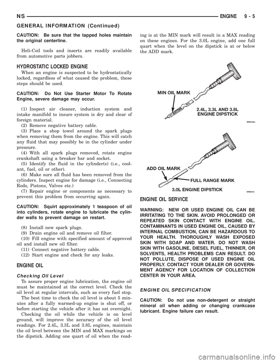
readings. For 2.4L, 3.3L and 3.8L engines, maintain
the oil level between the MIN and MAX markings on
the dipstick. Adding one quart of oil when the read-ing is at the MIN mark will result in a MAX reading
on these engines. For the 3.0L engine, add one full
quart when the level on the dipstick is at or below
the ADD mark.
ENGINE OIL SERVICE
WARNING: NEW OR USED ENGINE OIL CAN BE
IRRITATING TO THE SKIN. AVOID PROLONGED OR
REPEATED SKIN CONTACT WITH ENGINE OIL.
CONTAMINANTS IN USED ENGINE OIL, CAUSED BY
INTERNAL COMBUSTION, CAN BE HAZARDOUS TO
YOUR HEALTH. THOROUGHLY WASH EXPOSED
SKIN WITH SOAP AND WATER. DO NOT WASH
SKIN WITH GASOLINE, DIESEL FUEL, THINNER, OR
SOLVENTS, HEALTH PROBLEMS CAN RESULT. DO
NOT POLLUTE, DISPOSE OF USED ENGINE OIL
PROPERLY. CONTACT YOUR DEALER OR GOVERN-
MENT AGENCY FOR LOCATION OF COLLECTION
CENTER IN YOUR AREA.
ENGINE OIL SPECIFICATION
CAUTION: Do not use non-detergent or straight
mineral oil when adding or changing crankcase
lubricant. Engine failure can result.
NSENGINE 9 - 5
GENERAL INFORMATION (Continued)
Page 1056 of 1938
API SERVICE GRADE CERTIFIED
Use an engine oil that is API Service Grade Certi-
fied. MOPARtprovides engine oils that conforms to
this service grade.
SAE VISCOSITY
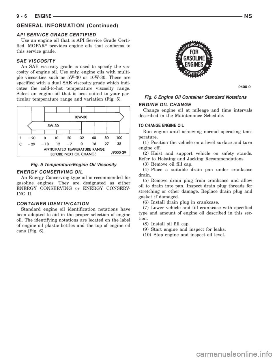
An SAE viscosity grade is used to specify the vis-
cosity of engine oil. Use only, engine oils with multi-
ple viscosities such as 5W-30 or 10W-30. These are
specified with a dual SAE viscosity grade which indi-
cates the cold-to-hot temperature viscosity range.
Select an engine oil that is best suited to your par-
ticular temperature range and variation (Fig. 5).
ENERGY CONSERVING OIL
An Energy Conserving type oil is recommended for
gasoline engines. They are designated as either
ENERGY CONSERVING or ENERGY CONSERV-
ING II.
CONTAINER IDENTIFICATION
Standard engine oil identification notations have
been adopted to aid in the proper selection of engine
oil. The identifying notations are located on the label
of engine oil plastic bottles and the top of engine oil
cans (Fig. 6).
ENGINE OIL CHANGE
Change engine oil at mileage and time intervals
described in the Maintenance Schedule.
TO CHANGE ENGINE OIL
Run engine until achieving normal operating tem-
perature.
(1) Position the vehicle on a level surface and turn
engine off.
(2) Hoist and support vehicle on safety stands.
Refer to Hoisting and Jacking Recommendations.
(3) Remove oil fill cap.
(4) Place a suitable drain pan under crankcase
drain.
(5) Remove drain plug from crankcase and allow
oil to drain into pan. Inspect drain plug threads for
stretching or other damage. Replace drain plug and
gasket if damaged.
(6) Install drain plug in crankcase.
(7) Lower vehicle and fill crankcase with specified
type and amount of engine oil described in this sec-
tion.
(8) Install oil fill cap.
(9) Start engine and inspect for leaks.
(10) Stop engine and inspect oil level.
Fig. 5 Temperature/Engine Oil Viscosity
Fig. 6 Engine Oil Container Standard Notations
9 - 6 ENGINENS
GENERAL INFORMATION (Continued)
Page 1058 of 1938
cause of low compression unless some malfunc-
tion is present.
(11) Clean or replace spark plugs as necessary
and adjust gap as specified in Group 8, Electrical.
Tighten to specifications.
(12) Test resistance of spark plug cables. Refer to
Group 8, Electrical Ignition System Secondary Cir-
cuit Inspection.
(13) Test coil output voltage, primary and second-
ary resistance. Replace parts as necessary. Refer to
Group 8, Electrical Ignition System.
(14) Check fuel pump pressure at idle and differ-
ent RPM ranges. Refer to Group 14, Fuel System for
Specifications.
(15) The air filter elements should be replaced as
specified in Group 0, Lubrication and Maintenance,.
(16) Inspect crankcase ventilation system as out
lined in Group 0, Lubrication and Maintenance. For
emission controls see Group 25, Emission Controls
for service procedures.
(17) Inspect and adjust accessory belt drives refer-
ring to Group 7, Cooling System, Accessory Drive
Belts for proper adjustments.
(18) Road test vehicle as a final test.
CYLINDER COMBUSTION PRESSURE LEAKAGE
TEST
The combustion pressure leakage test provides an
accurate means for determining engine condition.
Combustion pressure leakage testing will detect:
²Exhaust and intake valve leaks (improper seat-
ing).
²Leaks between adjacent cylinders or into water
jacket.
²Any causes for combustion/compression pressure
loss.
WARNING: DO NOT REMOVE THE RADIATOR CAP
WITH THE SYSTEM HOT AND UNDER PRESSURE
BECAUSE SERIOUS BURNS FROM COOLANT CAN
OCCUR.
Check the coolant level and fill as required. DO
NOT install the radiator cap.
Start and operate the engine until it attains nor-
mal operating temperature, then turn the engine
OFF.
Clean spark plug recesses with compressed air.
Remove the spark plugs.
Remove the oil filler cap.
Remove the air cleaner.
Calibrate the tester according to the manufactur-
er's instructions. The shop air source for testing
should maintain 483 kPa (70 psi) minimum, 1 379
kPa (200 psi) maximum and 552 kPa (80 psi) recom-
mended.Perform the test procedures on each cylinder
according to the tester manufacturer's instructions.
While testing, listen for pressurized air escaping
through the throttle body, tailpipe and oil filler cap
opening. Check for bubbles in the radiator coolant.
All gauge pressure indications should be equal,
with no more than 25% leakage.
FOR EXAMPLE:At 552 kPa (80 psi) input pres-
sure, a minimum of 414 kPa (60 psi) should be main-
tained in the cylinder.
LASH ADJUSTER (TAPPET) NOISE DIAGNOSIS
A tappet-like noise may be produced from several
items. Check the following items.
(1) Engine oil level too high or too low. This may
cause aerated oil to enter the adjusters and cause
them to be spongy.
(2) Insufficient running time after rebuilding cylin-
der head. Low speed running up to 1 hour may be
required.
(3) During this time, turn engine off and let set for
a few minutes before restarting. Repeat this several
times after engine has reached normal operating
temperature.
(4) Low oil pressure.
(5) The oil restrictor pressed into the vertical oil
passage to the cylinder head is plugged with debris.
(6) Air ingested into oil due to broken or cracked
oil pump pick up.
(7) Worn valve guides.
(8) Rocker arm ears contacting valve spring
retainer.
(9) Rocker arm loose, adjuster stuck or at maxi-
mum extension and still leaves lash in the system.
(10) Faulty lash adjuster.
a. Check lash adjusters for sponginess while
installed in cylinder head. Depress part of rocker
arm over adjuster. Normal adjusters should feel very
firm. Spongy adjusters can be bottomed out easily.
b. Remove suspected lash adjusters, and disassem-
bleDo not reuse retainer caps. Do not inter-
change parts and make sure that care and
cleanliness is exercised in the handling of parts.
c. Clean out dirt and varnish with solvent.
d. Reassemble with engine oil.
e. Check for sponginess.
f. If still spongy, replace with new adjuster.
INSPECTION (ENGINE OIL LEAKS IN GENERAL)
Begin with a through visual inspection of the
engine, particularly at the area of the suspected leak.
If an oil leak source is not readily identifiable, the
following steps should be followed:
(1) Do not clean or degrease the engine at this
time because some solvents may cause rubber to
swell, temporarily stopping the leak.
9 - 8 ENGINENS
DIAGNOSIS AND TESTING (Continued)
Page 1225 of 1938
HYDRAULIC TAPPETS
Before disassembling any part of the engine to cor-
rect tappet noise, check the oil pressure. If vehicle
has no oil pressure gauge, install a reliable gauge at
the pressure sending unit. The pressure should be
between 3.5 bars to 5.0 bars at 4000 RPM.
Check the oil level after the engine reaches normal
operating temperature. Allow 5 minutes to stabilize
oil level, check dipstick. The oil level in the pan
should never be above the FULL mark or below the
ADD OIL mark on dipstick. Either of these 2 condi-
tions could be responsible for noisy tappets.
OIL LEVEL HIGH
If oil level is above the FULL mark, it is possible
for the connecting rods to dip into the oil. With the
engine running, this condition could create foam in
the oil pan. Foam in oil pan would be fed to the
hydraulic tappets by the oil pump causing them to
lose length and allow valves to seat noisily.
OIL LEVEL LOW
Low oil level may allow oil pump to take in air.
When air is fed to the tappets, they lose length which
allows valves to seat noisily. Any leaks on intake side
of oil pump through which air can be drawn will cre-
ate the same tappet action. Check the lubrication
system from the intake strainer to the pump cover,
including the relief valve retainer cap. When tappet
noise is due to aeration, it may be intermittent or
constant, and usually more than 1 tappet will be
noisy. When oil level and leaks have been corrected,
operate the engine at fast idle. Run engine for a suf-
ficient time to allow all of the air inside the tappets
to be bled out.
TAPPET NOISE DIAGNOSIS
(1) To determine source of tappet noise, operate
engine at idle with cylinder head covers removed.
(2) Feel each valve spring or rocker arm to detect
noisy tappet. The noisy tappet will cause the affected
spring and/or rocker arm to vibrate or feel rough in
operation.
NOTE: Worn valve guides or cocked springs are
sometimes mistaken for noisy tappets. If such is
the case, noise may be dampened by applying side
thrust on the valve spring. If noise is not apprecia-
bly reduced, it can be assumed the noise is in the
tappet. Inspect the rocker arm push rod sockets
and push rod ends for wear.
(3) Valve tappet noise ranges from light noise to a
heavy click. A light noise is usually caused by exces-
sive leak down around the unit plunger or by the
plunger partially sticking in the tappet body cylinder.
The tappet should be replaced. A heavy click iscaused by a tappet check valve not seating or by for-
eign particles becoming wedged between the plunger
and the tappet body. This will cause the plunger to
stick in the down position. This heavy click will be
accompanied by excessive clearance between the
valve stem and rocker arm as valve closes. In either
case, tappet assembly should be removed for inspec-
tion and cleaning.
(4) The valve train generates a noise very much
like a light tappet noise during normal operation.
Care must be taken to ensure that tappets are mak-
ing the noise. In general, if more than one tappet
seems to be noisy, its probably not the tappets.
SERVICE PROCEDURES
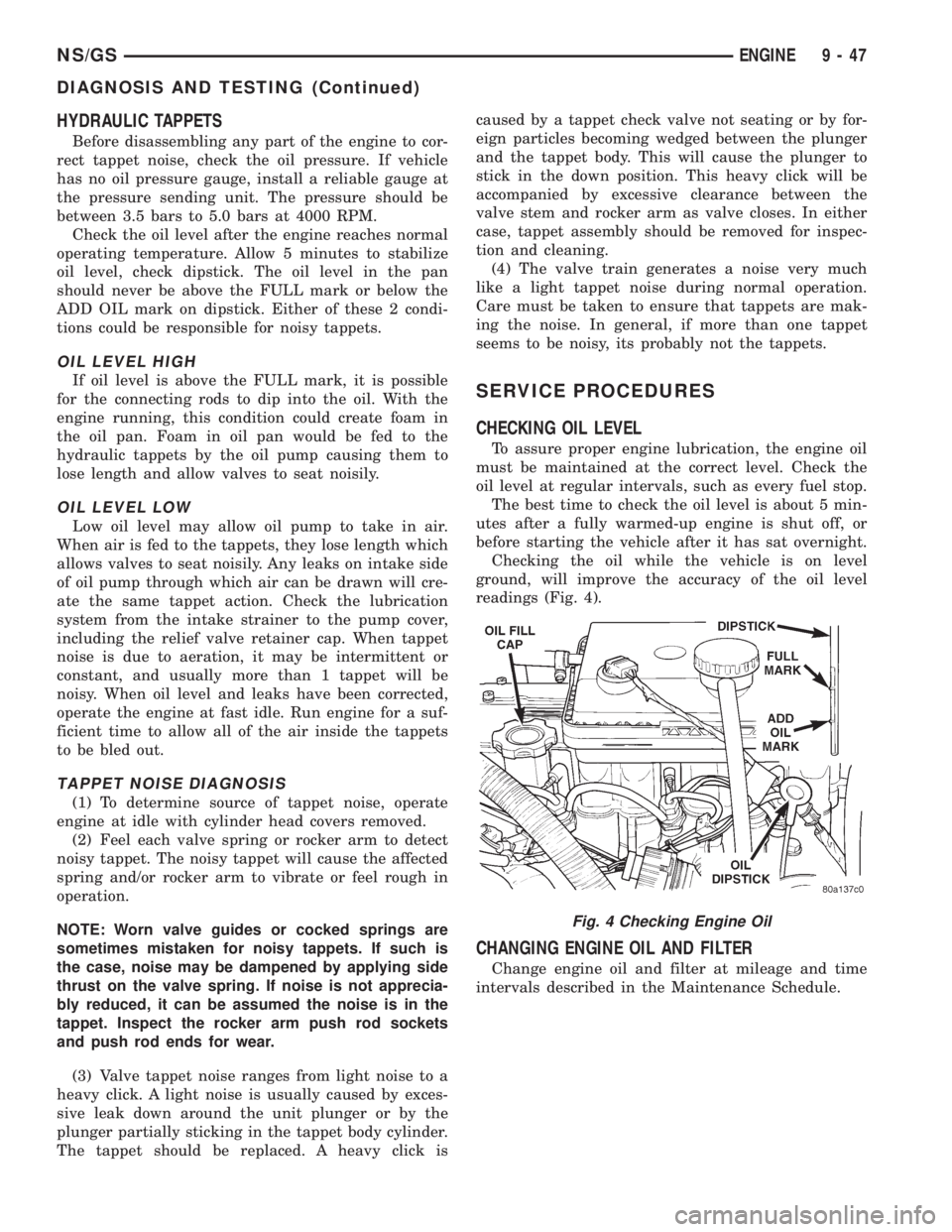
CHECKING OIL LEVEL
To assure proper engine lubrication, the engine oil
must be maintained at the correct level. Check the
oil level at regular intervals, such as every fuel stop.
The best time to check the oil level is about 5 min-
utes after a fully warmed-up engine is shut off, or
before starting the vehicle after it has sat overnight.
Checking the oil while the vehicle is on level
ground, will improve the accuracy of the oil level
readings (Fig. 4).
CHANGING ENGINE OIL AND FILTER
Change engine oil and filter at mileage and time
intervals described in the Maintenance Schedule.
Fig. 4 Checking Engine Oil
NS/GSENGINE 9 - 47
DIAGNOSIS AND TESTING (Continued)
Page 1226 of 1938
ENGINE OIL CHANGE
WARNING: NEW OR USED ENGINE OIL CAN BE
IRRITATING TO THE SKIN. AVOID PROLONGED OR
REPEATED SKIN CONTACT WITH ENGINE OIL.
CONTAMINANTS IN USED ENGINE OIL, CAUSED BY
INTERNAL COMBUSTION, CAN BE HAZARDOUS TO
YOUR HEALTH. THOROUGHLY WASH EXPOSED
SKIN WITH SOAP AND WATER. DO NOT WASH
SKIN WITH GASOLINE, DIESEL FUEL, THINNER, OR
SOLVENTS, HEALTH PROBLEMS CAN RESULT. DO
NOT POLLUTE, DISPOSE OF USED ENGINE OIL
PROPERLY. CONTACT YOUR DEALER OR GOVERN-
MENT AGENCY FOR LOCATION OF COLLECTION
CENTER IN YOUR AREA.
Run engine until achieving normal operating tem-
perature.
(1) Position the vehicle on a level surface and turn
engine off.
(2) Remove oil fill cap.
(3) Hoist vehicle. Refer to Hoisting and Jacking
Recommendations.
(4) Place a suitable drain pan under crankcase
drain.
(5) Remove drain plug from crankcase and allow
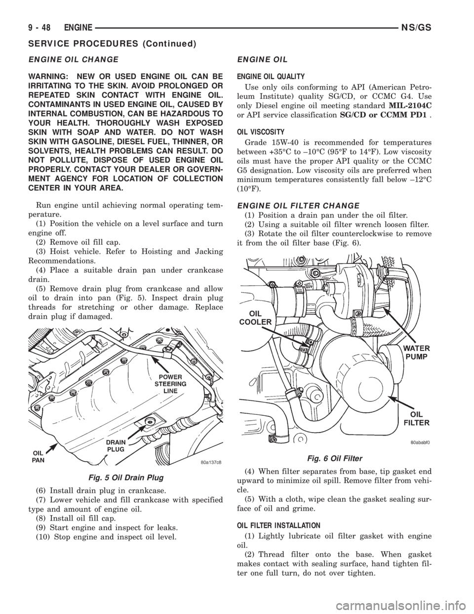
oil to drain into pan (Fig. 5). Inspect drain plug
threads for stretching or other damage. Replace
drain plug if damaged.
(6) Install drain plug in crankcase.
(7) Lower vehicle and fill crankcase with specified
type and amount of engine oil.
(8) Install oil fill cap.
(9) Start engine and inspect for leaks.
(10) Stop engine and inspect oil level.
ENGINE OIL
ENGINE OIL QUALITY
Use only oils conforming to API (American Petro-
leum Institute) quality SG/CD, or CCMC G4. Use
only Diesel engine oil meeting standardMIL-2104C
or API service classificationSG/CD or CCMM PD1.
OIL VISCOSITY
Grade 15W-40 is recommended for temperatures
between +35ÉC to ±10ÉC (95ÉF to 14ÉF). Low viscosity
oils must have the proper API quality or the CCMC
G5 designation. Low viscosity oils are preferred when
minimum temperatures consistently fall below ±12ÉC
(10ÉF).
ENGINE OIL FILTER CHANGE
(1) Position a drain pan under the oil filter.
(2) Using a suitable oil filter wrench loosen filter.
(3) Rotate the oil filter counterclockwise to remove
it from the oil filter base (Fig. 6).
(4) When filter separates from base, tip gasket end
upward to minimize oil spill. Remove filter from vehi-
cle.
(5) With a cloth, wipe clean the gasket sealing sur-
face of oil and grime.
OIL FILTER INSTALLATION
(1) Lightly lubricate oil filter gasket with engine
oil.
(2) Thread filter onto the base. When gasket
makes contact with sealing surface, hand tighten fil-
ter one full turn, do not over tighten.
Fig. 5 Oil Drain Plug
Fig. 6 Oil Filter
9 - 48 ENGINENS/GS
SERVICE PROCEDURES (Continued)
Page 1312 of 1938
INSTALLATION
(1) Position fuel tank on transmission jack. Con-
nect pressure relief/rollover valve hose. Connect fuel
filler tube vent hose and replace clamp.
(2) Raise tank into position and carefully work
filler tube into tank. A light coating of clean engine
oil on the tube end may be used to aid assembly.
(3) Feed filler vent line thru frame rail. Careful
not to cross lines.
(4) Tighten strap bolts to 54 N´m (40 ft. lbs.)
torque. Remove transmission jack.
(5) Tighten filler hose clamp to 3.3 N´m (30 in.
lbs.).
CAUTION: Ensure straps are not twisted or bent
before or after tightening strap nuts.
(6) Connect fuel pump/module electrical connector.
Place retainer in locked position.
(7) Lubricate the fuel supply line with clean 30
weight engine oil, install the quick connect fuel fit-
ting. Refer to Tube/Fitting Assembly in the Fuel
Delivery section of this Group.
(8) Attach filler line to filler tube. Pull on connec-
tor to make sure of connection.
(9) Fill fuel tank, replace cap, and connect battery
negative cable.
CAUTION: When using the ASD Fuel System Test,
the ASD relay and fuel pump relay remain energized
for 7 minutes or until the test is stopped, or until
the ignition switch is turned to the Off position.
(10) Use the DRB scan tool ASD Fuel System Test
to pressurize the fuel system. Check for leaks.
FUEL INJECTOR RAILÐ2.4L
REMOVAL
(1) Perform fuel system pressure release procedure
before servicing or starting repairs.Refer to
Fuel System Pressure Release Procedure in this sec-
tion.
(2) Disconnect negative cable from battery.
(3) Remove air cleaner inlet hose from throttle
body.
(4) Remove throttle cable and speed control cable
(if equipped) from throttle lever.
(5) Remove throttle cables from bracket by com-
pressing retaining tabs.
(6) Remove connector from throttle position sensor.
(7) Remove connector from idle air control motor.
(8) Remove vacuum lines from intake plenum fit-
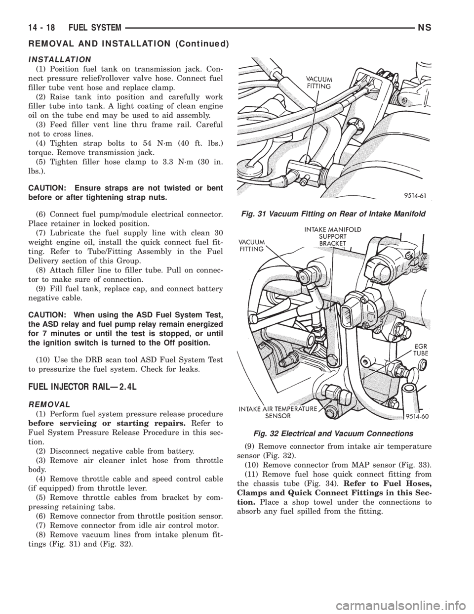
tings (Fig. 31) and (Fig. 32).(9) Remove connector from intake air temperature
sensor (Fig. 32).
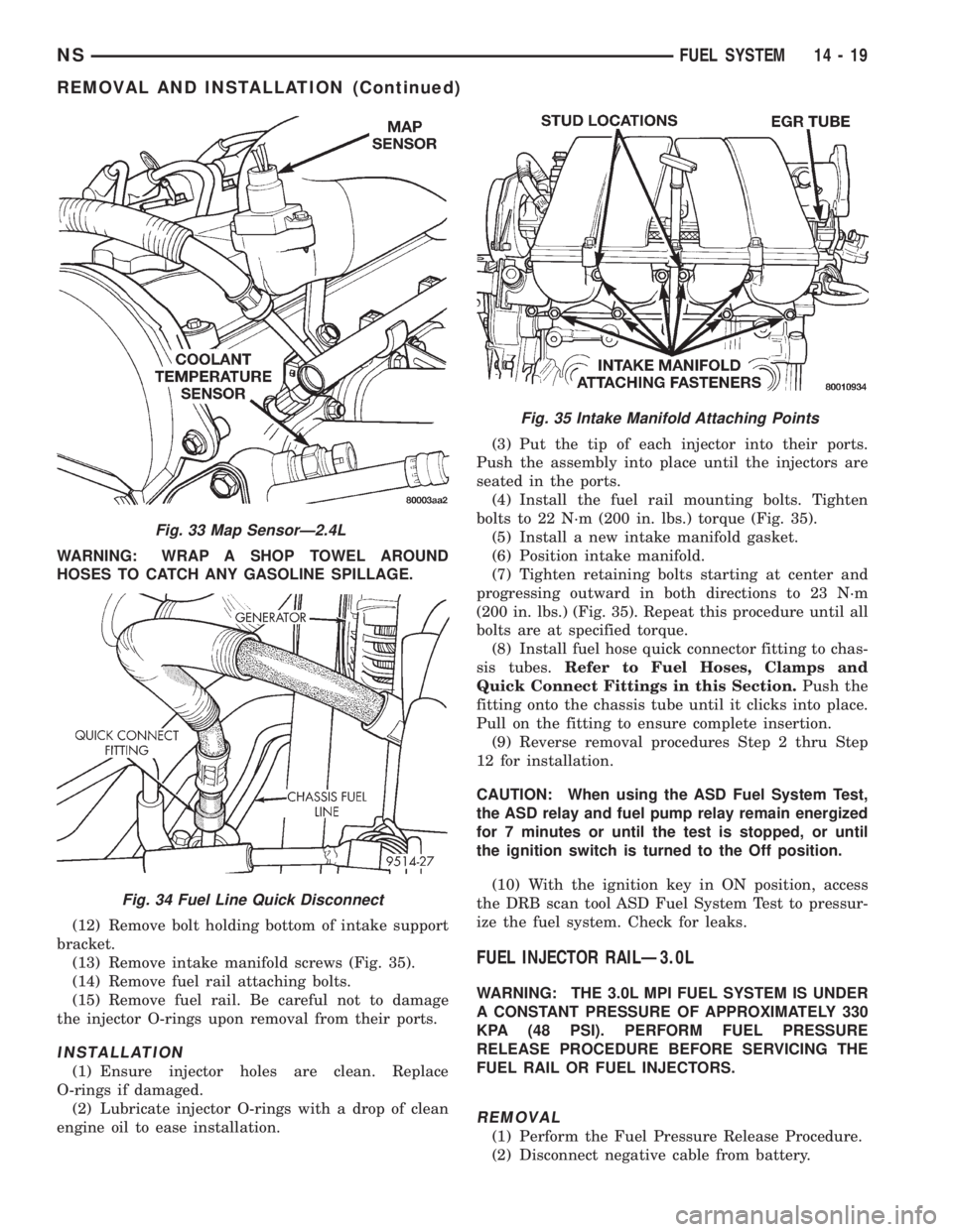
(10) Remove connector from MAP sensor (Fig. 33).
(11) Remove fuel hose quick connect fitting from
the chassis tube (Fig. 34).Refer to Fuel Hoses,
Clamps and Quick Connect Fittings in this Sec-
tion.Place a shop towel under the connections to
absorb any fuel spilled from the fitting.
Fig. 31 Vacuum Fitting on Rear of Intake Manifold
Fig. 32 Electrical and Vacuum Connections
14 - 18 FUEL SYSTEMNS
REMOVAL AND INSTALLATION (Continued)
Page 1313 of 1938
WARNING: WRAP A SHOP TOWEL AROUND
HOSES TO CATCH ANY GASOLINE SPILLAGE.
(12) Remove bolt holding bottom of intake support
bracket.
(13) Remove intake manifold screws (Fig. 35).
(14) Remove fuel rail attaching bolts.
(15) Remove fuel rail. Be careful not to damage
the injector O-rings upon removal from their ports.
INSTALLATION
(1) Ensure injector holes are clean. Replace
O-rings if damaged.
(2) Lubricate injector O-rings with a drop of clean
engine oil to ease installation.(3) Put the tip of each injector into their ports.
Push the assembly into place until the injectors are
seated in the ports.
(4) Install the fuel rail mounting bolts. Tighten
bolts to 22 N´m (200 in. lbs.) torque (Fig. 35).
(5) Install a new intake manifold gasket.
(6) Position intake manifold.
(7) Tighten retaining bolts starting at center and
progressing outward in both directions to 23 N´m
(200 in. lbs.) (Fig. 35). Repeat this procedure until all
bolts are at specified torque.
(8) Install fuel hose quick connector fitting to chas-
sis tubes.Refer to Fuel Hoses, Clamps and
Quick Connect Fittings in this Section.Push the
fitting onto the chassis tube until it clicks into place.
Pull on the fitting to ensure complete insertion.
(9) Reverse removal procedures Step 2 thru Step
12 for installation.
CAUTION: When using the ASD Fuel System Test,
the ASD relay and fuel pump relay remain energized
for 7 minutes or until the test is stopped, or until
the ignition switch is turned to the Off position.
(10) With the ignition key in ON position, access
the DRB scan tool ASD Fuel System Test to pressur-
ize the fuel system. Check for leaks.
FUEL INJECTOR RAILÐ3.0L
WARNING: THE 3.0L MPI FUEL SYSTEM IS UNDER
A CONSTANT PRESSURE OF APPROXIMATELY 330
KPA (48 PSI). PERFORM FUEL PRESSURE
RELEASE PROCEDURE BEFORE SERVICING THE
FUEL RAIL OR FUEL INJECTORS.
REMOVAL
(1) Perform the Fuel Pressure Release Procedure.
(2) Disconnect negative cable from battery.
Fig. 33 Map SensorÐ2.4L
Fig. 34 Fuel Line Quick Disconnect
Fig. 35 Intake Manifold Attaching Points
NSFUEL SYSTEM 14 - 19
REMOVAL AND INSTALLATION (Continued)