stop start CHRYSLER VOYAGER 1996 Owner's Manual
[x] Cancel search | Manufacturer: CHRYSLER, Model Year: 1996, Model line: VOYAGER, Model: CHRYSLER VOYAGER 1996Pages: 1938, PDF Size: 55.84 MB
Page 1373 of 1938
For periodic draining of water from the bowl, refer
to Fuel Filter/Water Separator Removal/Installation
in this group.
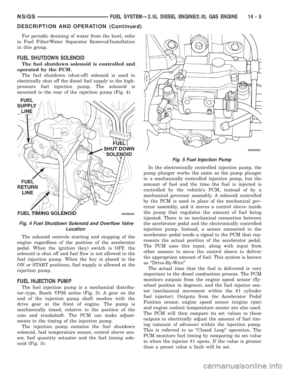
FUEL SHUTDOWN SOLENOID
The fuel shutdown solenoid is controlled and
operated by the PCM.
The fuel shutdown (shut-off) solenoid is used to
electrically shut off the diesel fuel supply to the high-
pressure fuel injection pump. The solenoid is
mounted to the rear of the injection pump (Fig. 4).
The solenoid controls starting and stopping of the
engine regardless of the position of the accelerator
pedal. When the ignition (key) switch is OFF, the
solenoid is shut off and fuel flow is not allowed to the
fuel injection pump. When the key is placed in the
ON or START positions, fuel supply is allowed at the
injection pump.
FUEL INJECTION PUMP
The fuel injection pump is a mechanical distribu-
tor±type, Bosch VP36 series (Fig. 5). A gear on the
end of the injection pump shaft meshes with the
drive gear at the front of engine. The pump is
mechanically timed, relative to the position of the
cam and crankshaft. The PCM can make adjust-
ments to the timing of the injection pump.
The injection pump contains the fuel shutdown
solenoid, fuel temperature sensor, control sleeve sen-
sor, fuel quantity actuator and the fuel timing sole-
noid (Fig. 5).In the electronically controlled injection pump, the
pump plunger works the same as the pump plunger
in a mechanically controlled injection pump, but the
amount of fuel and the time the fuel is injected is
controlled by the vehicle's PCM, instead of by a
mechanical governor assembly. A solenoid controlled
by the PCM is used in place of the mechanical gov-
ernor assembly, and it moves a control sleeve inside
the pump that regulates the amount of fuel being
injected. There is no mechanical connection between
the accelerator pedal and the electronically controlled
injection pump. Instead, a sensor connected to the
accelerator pedal sends a signal to the PCM that rep-
resents the actual position of the accelerator pedal.
The PCM uses this input, along with input from
other sensors to move the control sleeve to deliver
the appropriate amount of fuel. This system is known
as ªDrive-By-Wireº
The actual time that the fuel is delivered is very
important to the diesel combustion process. The PCM
monitors outputs from the engine speed sensor (fly-
wheel position in degrees), and the fuel injector sen-
sor (mechanical movement within the #1 cylinder
fuel injector). Outputs from the Accelerator Pedal
Position sensor, engine speed sensor (engine rpm)
and engine coolant temperature sensor are also used.
The PCM will then compare its set values to these
outputs to electrically adjust the amount of fuel tim-
ing (amount of advance) within the injection pump.
This is referred to as ªClosed Loopº operation. The
PCM monitors fuel timing by comparing its set value
to when the injector #1 opens. If the value is greater
than a preset value a fault will be set.
Fig. 4 Fuel Shutdown Solenoid and Overflow Valve
Location
Fig. 5 Fuel Injection Pump
NS/GSFUEL SYSTEMÐ2.5L DIESEL ENGINE/2.0L GAS ENGINE 14 - 5
DESCRIPTION AND OPERATION (Continued)
Page 1381 of 1938
A defective fuel injection pump, defective fuel tim-
ing solenoid or misadjusted mechanical pump timing
can cause starting problems or prevent the engine
from revving up. It can also cause:
²Engine surge at idle
²Rough idle (warm engine)
²Low power
²Excessive fuel consumption
²Poor performance
²Low power
²Black smoke from the exhaust
²Blue or white fog like exhaust
²Incorrect idle or maximum speed
The electronically controlled fuel pump has no
mechanical governor like older mechanically con-
trolled fuel pumps. Do not remove the top cover of
the fuel pump, or the screws fastening the wiring
pigtail to the side of the pump.The warranty of
the injection pump and the engine may be void
if those seals have been removed or tampered
with.
FUEL SUPPLY RESTRICTIONS
LOW±PRESSURE LINES
Restricted or Plugged supply lines or fuel filter can
cause a timing fault that will cause the PCM to oper-
ate the engine in a ªLimp Homeº mode. See the
introduction of the Fuel Injection System in this
group for more information on the Limp Home mode.
Fuel supply line restrictions can cause starting prob-
lems and prevent the engine from revving up. The
starting problems include; low power and blue or
white fog like exhaust. Test all fuel supply lines for
restrictions or blockage. Flush or replace as neces-
sary. Bleed the fuel system of air once a fuel supply
line has been replaced. Refer to the Air Bleed Proce-
dure section of this group for procedures.
HIGH±PRESSURE LINES
Restricted (kinked or bent) high±pressure lines can
cause starting problems, poor engine performance
and black smoke from exhaust.
Examine all high±pressure lines for any damage.
Each radius on each high±pressure line must be
smooth and free of any bends or kinks.
Replace damaged, restricted or leaking high±pres-
sure fuel lines with the correct replacement line.
CAUTION: The high±pressure fuel lines must be
clamped securely in place in the holders. The lines
cannot contact each other or other components. Do
not attempt to weld high±pressure fuel lines or to
repair lines that are damaged. Only use the recom-
mended lines when replacement of high±pressure
fuel line is necessary.
FUEL SHUTDOWN SOLENOID TEST
Since diesel fuel injection does not use spark plugs
to start combustion, the only way to stop the engine
is to cut off the fuel supply. This is done with the
Fuel Shutdown Solenoid. If the engine cranks, but
refuses to start, it may be caused by a defective fuel
shutdown solenoid.
The fuel shutdown solenoid is not controlled
or operated by the PCM.Voltage to operate the
solenoid is supplied from the ignition (key) switch.
NOTE: Although the fuel shutdown solenoid is not
operated by the PCM, if the Fuel Shutdown Solenoid
has been disconnected, and the key turned on, the
PCM will sense that the solenoid is not in the circuit,
and will switch to a ªLimp Homeº mode. After recon-
necting the solenoid, the PCM will have to be reset
by clearing the codes with the DRBIII scan tool, or
disconnecting the vehicle's battery for several min-
utes. The DRBIII scan tool is the preferred method
for resetting the PCM. Refer to the 1998 GS 2.5L Die-
sel Powertrain Diagnostic Manual for procedure.
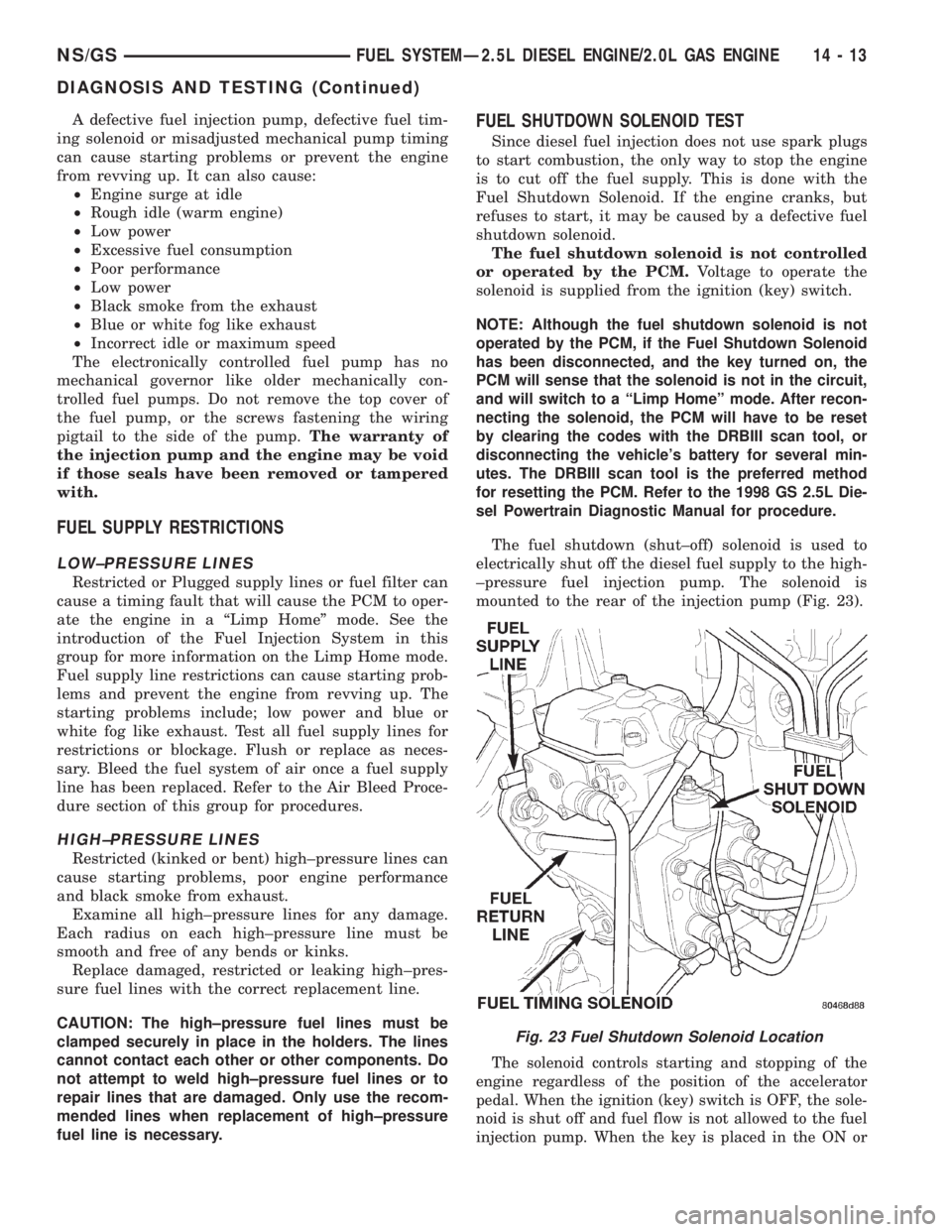
The fuel shutdown (shut±off) solenoid is used to
electrically shut off the diesel fuel supply to the high-
±pressure fuel injection pump. The solenoid is
mounted to the rear of the injection pump (Fig. 23).
The solenoid controls starting and stopping of the
engine regardless of the position of the accelerator
pedal. When the ignition (key) switch is OFF, the sole-
noid is shut off and fuel flow is not allowed to the fuel
injection pump. When the key is placed in the ON or
Fig. 23 Fuel Shutdown Solenoid Location
NS/GSFUEL SYSTEMÐ2.5L DIESEL ENGINE/2.0L GAS ENGINE 14 - 13
DIAGNOSIS AND TESTING (Continued)
Page 1414 of 1938
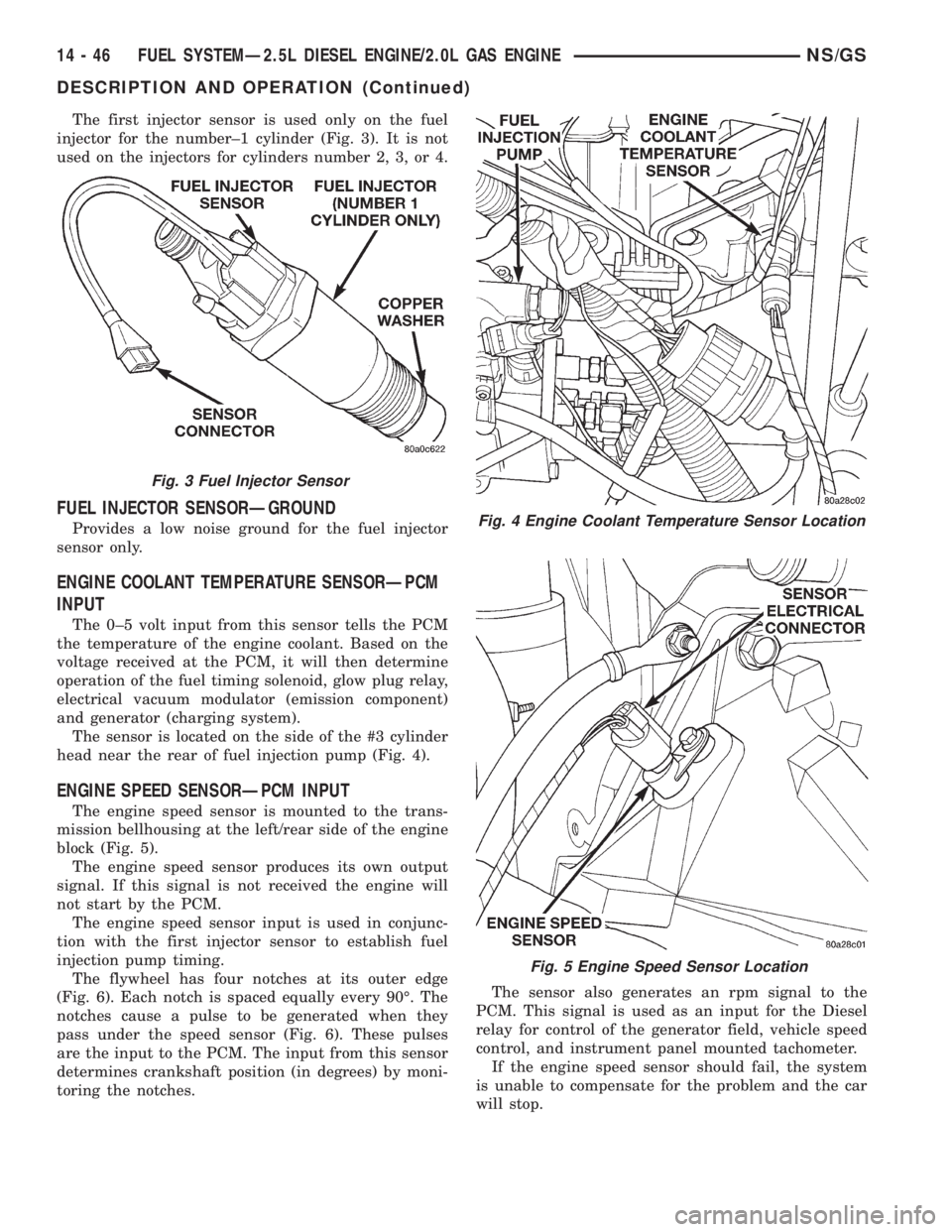
The first injector sensor is used only on the fuel
injector for the number±1 cylinder (Fig. 3). It is not
used on the injectors for cylinders number 2, 3, or 4.
FUEL INJECTOR SENSORÐGROUND
Provides a low noise ground for the fuel injector
sensor only.
ENGINE COOLANT TEMPERATURE SENSORÐPCM
INPUT
The 0±5 volt input from this sensor tells the PCM
the temperature of the engine coolant. Based on the
voltage received at the PCM, it will then determine
operation of the fuel timing solenoid, glow plug relay,
electrical vacuum modulator (emission component)
and generator (charging system).
The sensor is located on the side of the #3 cylinder
head near the rear of fuel injection pump (Fig. 4).
ENGINE SPEED SENSORÐPCM INPUT
The engine speed sensor is mounted to the trans-
mission bellhousing at the left/rear side of the engine
block (Fig. 5).
The engine speed sensor produces its own output
signal. If this signal is not received the engine will
not start by the PCM.
The engine speed sensor input is used in conjunc-
tion with the first injector sensor to establish fuel
injection pump timing.
The flywheel has four notches at its outer edge
(Fig. 6). Each notch is spaced equally every 90É. The
notches cause a pulse to be generated when they
pass under the speed sensor (Fig. 6). These pulses
are the input to the PCM. The input from this sensor
determines crankshaft position (in degrees) by moni-
toring the notches.The sensor also generates an rpm signal to the
PCM. This signal is used as an input for the Diesel
relay for control of the generator field, vehicle speed
control, and instrument panel mounted tachometer.
If the engine speed sensor should fail, the system
is unable to compensate for the problem and the car
will stop.
Fig. 3 Fuel Injector Sensor
Fig. 4 Engine Coolant Temperature Sensor Location
Fig. 5 Engine Speed Sensor Location
14 - 46 FUEL SYSTEMÐ2.5L DIESEL ENGINE/2.0L GAS ENGINENS/GS
DESCRIPTION AND OPERATION (Continued)
Page 1416 of 1938
The speed sensor generates 8 pulses per sensor
revolution. These signals, in conjunction with a
closed throttle signal from the throttle position sen-
sor, indicate a closed throttle deceleration to the
PCM. When the vehicle is stopped at idle, a closed
throttle signal is received by the PCM (but a speed
sensor signal is not received).
In addition to determining distance and vehicle
speed, the output from the sensor is used to control
speed control operation.
SPEED CONTROLÐPCM INPUTS
The speed control system provides five separate
inputs to the PCM; On/Off, Set, Resume/Accel, Cancel,
and Decel.. The On/Off input informs the PCM that
the speed control system has been activated. The Set
input informs the PCM that a fixed vehicle speed has
been selected. The Resume input indicates to the PCM
that the previous fixed speed is requested.
Speed control operation will start at 50 km/h±142
km/h (35±85 mph). The upper range of operation is
not restricted by vehicle speed. Inputs that affect
speed control operation are vehicle speed sensor and
throttle position sensor.
Refer to Group 8H for further speed control infor-
mation.
DIESEL PCM RELAYÐPCM INPUT
A 12 volt signal at this input indicates to the PCM
that the Diesel relay has been activated. The Diesel
relay is located in the PDC. The PDC is located next
to the battery in the engine compartment. For the
location of the relay within the PDC, refer to label on
PDC cover.
This input is used only to sense that the Diesel
relay is energized. If the PCM does not see 12 volts +
at this input when the Diesel relay should be acti-
vated, it will set a Diagnostic Trouble Code (DTC).
FIVE VOLT POWERÐPCM OUTPUT
This circuit supplies approximately 5 volts to
power the Accelerator Pedal Postion Sensor, Mass Air
Flow Sensor, and A/C Pressure Sensor.
ENGINE COOLANT GAUGEÐPCM OUTPUT
Refer to the Instrument Panel and Gauges group
for additional information.
ENGINE OIL PRESSURE GAUGEÐPCM OUTPUT
Refer to the Instrument Panel and Gauges group
for additional information.
GLOW PLUG LAMPÐPCM OUTPUT
The Glow Plug lamp (malfunction indicator lamp)
illuminates on the message center each time the igni-
tion (key) switch is turned on. It will stay on for
about two seconds as a bulb test.If the PCM receives an incorrect signal, or no sig-
nal from certain sensors or components, the lamp
BLINKS. This is a warning that the PCM has
recorded a system or sensor malfunction. It signals
an immediate need for service. There are only 5
HARD faults that can turn on this lamp to make it
blink.
SPEED CONTROLÐPCM OUTPUTS
These two circuits control the fuel quantity actua-
tor to regulate vehicle speed. Refer to Group 8H for
Speed Control information.
AIR CONDITIONING RELAYÐPCM OUTPUT
This circuit controls a ground signal for operation
of the A/C clutch relay. Also refer to Air Conditioning
(A/C) ControlsÐPCM Input for additional informa-
tion.
The A/C relay is located in the Power Distribution
Center (PDC). The PDC is located next to the battery
in the engine compartment. For the location of the
relay within the PDC, refer to label on PDC cover.
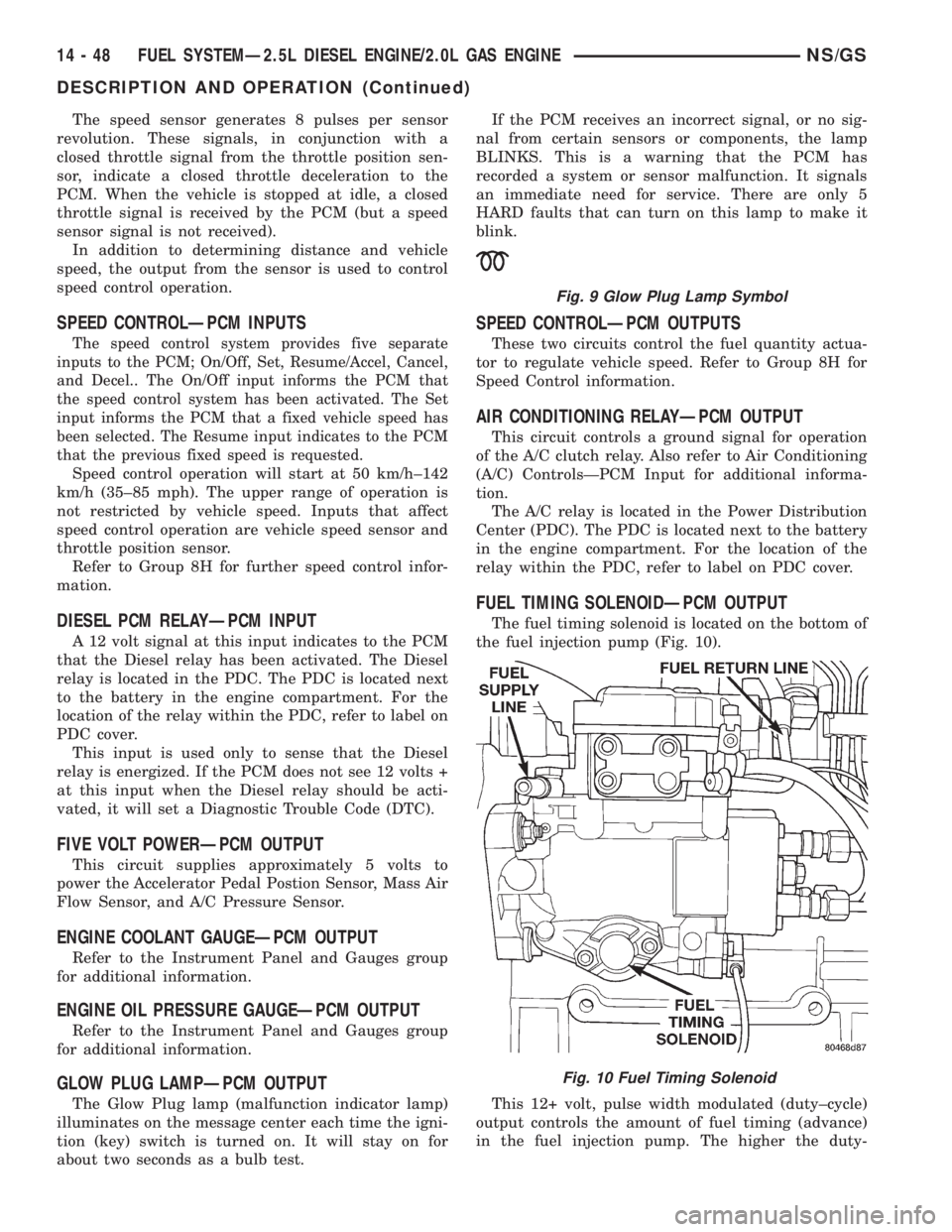
FUEL TIMING SOLENOIDÐPCM OUTPUT
The fuel timing solenoid is located on the bottom of
the fuel injection pump (Fig. 10).
This 12+ volt, pulse width modulated (duty±cycle)
output controls the amount of fuel timing (advance)
in the fuel injection pump. The higher the duty-
Fig. 9 Glow Plug Lamp Symbol
Fig. 10 Fuel Timing Solenoid
14 - 48 FUEL SYSTEMÐ2.5L DIESEL ENGINE/2.0L GAS ENGINENS/GS
DESCRIPTION AND OPERATION (Continued)
Page 1436 of 1938
POWER STEERING PUMP FLOW AND
PRESSURE TEST PROCEDURE
(1) Check power steering pump drive belt tension
and adjust as necessary.
(2) Disconnect power steering fluid pressure hose,
at power steering pump. Use a container for dripping
fluid.
(3) Connect Pressure Gauge, Special Tool from kit
6815 to both hoses using adapter fittings. Connect
spare pressure hose, to power steering pump pres-
sure hose fitting.
(4) Completely open valve on Special Tool 6815.
(5) Start engine and let idle long enough to circu-
late power steering fluid through flow/pressure test
and get air out of fluid. Then shut off engine.
(6) Check power steering fluid level, and add fluid
as necessary. Start engine again and let idle.
(7) Pressure gauge should read below 862 kPa
(125 psi), if above, inspect the hoses for restrictions
and repair as necessary. The initial pressure reading
should be in the range of 345-552 kPa (50-80 psi).
The flow meter should read between 1.3 and 1.9
GPM
CAUTION: The following test procedure involves
testing power steering pump maximum pressure
output and flow control valve operation. Do not
leave valve closed for more than 5 seconds as the
pump could be damaged.
(8) Close valve fully three times and record high-
est pressure indicated each time.All three read-
ings must be within specifications and within
345 kPa (50 psi) of each other.
NOTE: Power steering pump maximum relief pres-
sure is 9653 to 10342 kPa (1400 to 1500 psi.).
²If power steering pump pressures are within the
specifications but not within 345 kPa (50 psi) of each
other, then replace power steering pump.
²If pressures are within 345 kPa (50 psi) of each
other but below specifications, then replace power
steering pump.
CAUTION: Do not force the pump to operate
against the stops for more than 5 seconds at a time
because, pump damage will result.
(9) Open test valve. Turn steering wheel to the
extreme left and right positions until against the
stops, recording the highest indicated pressure at
each position. Compare pressure gauge readings to
power steering pump specifications. If highest output
pressures are not the same against either stop, the
steering gear is leaking internally and must be
replaced.
SERVICE PROCEDURES
POWER STEERING SYSTEM FLUID LEVEL CHECK
WARNING: FLUID LEVEL SHOULD BE CHECKED
WITH ENGINE OFF TO PREVENT INJURY FROM
MOVING PARTS. DO NOT USE AUTOMATIC TRANS-
MISSION FLUID IN THE POWER STEERING SYS-
TEM. DO NOT OVERFILL THE POWER STEERING
SYSTEM.
Wipe reservoir filler cap free of dirt. Then check
fluid level. The dipstick should indicate COLD when
fluid is at normal ambient temperature, approxi-
mately 21ÉC to 27ÉC (70ÉF to 80ÉF). In all pumps add
fluid as necessary, use onlyMopar Power Steering
Fluid, or equivalent. DO NOT USE ANY TYPE
OF AUTOMATIC TRANSMISSION FLUID.
POWER STEERING PUMP INITIAL OPERATION
CAUTION: The fluid level should be checked with
engine off to prevent injury from moving compo-
nents. Use only MoparTPower Steering Fluid. Do
not use automatic transmission fluid. Do not over-
fill.
Wipe filler cap clean, then check the fluid level.
The dipstick should indicateFULL COLDwhen the
fluid is at normal temperature of approximately 21ÉC
to 27ÉC (70ÉF to 80ÉF).
(1) Fill the pump fluid reservoir to the proper level
and let the fluid settle for at least two (2) minutes.
(2) Start the engine and let run for a few seconds.
Then turn the engine off.
(3) Add fluid if necessary. Repeat the above proce-
dure until the fluid level remains constant after run-
ning the engine.
(4) Raise the front wheels off the ground.
(5) Start the engine. Slowly turn the steering
wheel right and left, lightly contacting the wheel
stops.
(6) Add power steering fluid if necessary.
(7) Lower the vehicle and turn the steering wheel
slowly from lock to lock.
(8) Stop the engine. Check the fluid level and refill
as required.
(9) If the fluid is extremely foamy, allow the vehi-
cle to stand a few minutes and repeat the above pro-
cedure.
19 - 10 STEERINGNS
DIAGNOSIS AND TESTING (Continued)
Page 1439 of 1938
(18) Remove the 3 previously loosened bolts
attaching the front bracket to the power steering
pump and separate the power steering pump from
the front bracket prior to removing the pump from
the vehicle.
(19) The power steering pump is removed from the
vehicle by pulling it out through the exhaust tunnel
area in the floor pan of the vehicle.
INSTALL
(1) Install power steering pump back in vehicle
using the reverse order of its removal through the
exhaust tunnel are of the vehicle.
(2) Install the power steering pump on its cast
mounting bracket and loosely install nut to hold
pump in place (Fig. 9).
(3) Install the front bracket on the power steering
pump and loosely install the 3 mounting bolts (Fig.
10). Then install the nut and bolt attaching the front
bracket to the cast bracket (Fig. 10).
(4) Tighten the 3 power steering pump mounting
bolts (Fig. 10) to a torque of 54 N´m (40 ft. lbs.).
NOTE: Before installing power steering fluid pres-
sure hose on power steering pump, inspect the
O-ring on the pressure hose for damage and
replace if necessary.
(5) Install the power steering fluid pressure line
onto the output fitting of the power steering pump
(Fig. 8). Tighten the pressure line to pump fitting
tube nut to a torque of 31 N´m (275 in. lbs.).
(6) Install the power steering fluid, low pressure
return hose on the power steering pump low pressure
fitting (Fig. 8).Be sure hose clamps are properly
reinstalled.
(7) Install the power steering fluid supply hose
from the power steering fluid reservoir, on the power
steering pump fluid fitting (Fig. 7).Be sure hose is
clear of accessory drive belts all hose clamps
are properly reinstalled.
(8) Install the power steering pump drive belt on
pulley. See Cooling, Group 7 for detailed installation
procedure.
(9) Install the accessory drive splash shield (Fig.
6).
(10) Install the power steering fluid return hose on
the steel tube at the front suspension cradle (Fig. 5).
(11) Install a screw type hose clamp on the power
steering hose to steel tube connection.Be sure hose
clamps are properly reinstalled.Tighten the screw
clamp to a torque of 2 N´m (18 in. lbs.).
CAUTION: The protective heat shield sleeves must
cover the entire rubber hose and hose to tube con-
nection portion of both the power steering fluid
pressure and return hoses (Fig. 5). This is requiredto prevent the overheating of the power steering
hoses.
(12) When used, properly position the protective
heat sleeves on the power steering hoses (Fig. 5).
Then, tie strap the heat sleeves to the power steering
hoses to keep them in their proper position.
(13) Install the exhaust pipe on the exhaust man-
ifold. Install all exhaust system hangers/isolators on
the exhaust system brackets.
(14) Connect the oxygen sensor wiring harness to
the vehicle wiring harness. Install wiring harness
grommet in the floor pan of the vehicle.
(15) Lower vehicle.
(16) Adjust the power steering pump drive belt.
See Cooling, Group 7 for detailed adjustment proce-
dure.
(17) Tighten the top nut and bottom bolt on the
power steering pump front mounting bracket (Fig. 3)
to a torque of 54 N´m (40 ft. lbs.).
CAUTION: Do not use automatic transmission fluid
in power steering system. Only use MoparT, Power
Steering Fluid, or equivalent.
(18) Fill the remote power steering pump fluid res-
ervoir to correct fluid level.
(19) Install cap on power steering fluid reservoir.
(20) Connect the negative battery cable on the
negative battery post.
(21) Start engine and turn steering wheel several
times from stop to stop to bleed air from fluid in sys-
tem. Stop engine, check fluid level, and inspect sys-
tem for leaks. See Checking Fluid Level.
3.0 LITER POWER STEERING PUMP
REMOVE
WARNING: POWER STEERING OIL, ENGINE COM-
PONENTS AND THE EXHAUST SYSTEM MAY BE
EXTREMELY HOT IF ENGINE HAS BEEN RUNNING.
DO NOT START ENGINE WITH ANY LOOSE OR DIS-
CONNECTED HOSES. DO NOT ALLOW HOSES TO
TOUCH HOT EXHAUST MANIFOLD OR CATALYST.
(1) Remove the (-) negative battery cable from the
battery and isolate cable.
(2) Remove cap from power steering fluid reser-
voir.
(3) Using a siphon pump, remove as much power
steering fluid as possible from the power steering
fluid reservoir.
NSSTEERING 19 - 13
REMOVAL AND INSTALLATION (Continued)
Page 1442 of 1938
(15) Fill the remote power steering pump fluid res-
ervoir to correct fluid level.
(16) Install cap on power steering fluid reservoir.
(17) Connect the negative battery cable on the
negative battery post.
(18) Start engine and turn steering wheel several
times from stop to stop to bleed air from fluid in sys-
tem. Stop engine, check fluid level, and inspect sys-
tem for leaks. See Checking Fluid Level.
3.3/3.8 LITER POWER STEERING PUMP
REMOVE
WARNING: POWER STEERING OIL, ENGINE COM-
PONENTS AND THE EXHAUST SYSTEM MAY BE
EXTREMELY HOT IF ENGINE HAS BEEN RUNNING.
DO NOT START ENGINE WITH ANY LOOSE OR DIS-
CONNECTED HOSES. DO NOT ALLOW HOSES TO
TOUCH HOT EXHAUST MANIFOLD OR CATALYST.
(1) Remove the (-) negative battery cable from the
battery and isolate cable.
(2) Remove cap from power steering fluid reser-
voir.
(3) Using a siphon pump, remove as much power
steering fluid as possible from the power steering
fluid reservoir.
(4) Raise vehicle on jack stands or centered on a
frame contact type hoist. See Hoisting, in the Lubri-
cation and Maintenance section of this service man-
ual for the required lifting procedure.
(5) Disconnect the oxygen sensor wiring harness
from the vehicle wiring harness. Access to connection
at vehicle wiring harness is through the oxygen sen-
sor wiring harness grommet in the floor pan of the
vehicle.
NOTE: The exhaust system needs to be removed
from the engine to allow for an area to remove the
power steering pump from the vehicle.
(6) Remove the catalytic converter from the
exhaust manifold. Then remove all the exhaust sys-
tem hangers/isolators from the brackets on the
exhaust system.
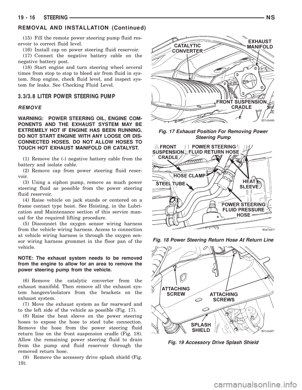
(7) Move the exhaust system as far rearward and
to the left side of the vehicle as possible (Fig. 17).
(8) Raise the heat sleeve on the power steering
hoses to expose the hose to steel tube connection.
Remove the hose from the power steering fluid
return line on the front suspension cradle (Fig. 18).
Allow the remaining power steering fluid to drain
from the pump and fluid reservoir through the
removed return hose.
(9) Remove the accessory drive splash shield (Fig.
19).
Fig. 17 Exhaust Position For Removing Power
Steering Pump
Fig. 18 Power Steering Return Hose At Return Line
Fig. 19 Accessory Drive Splash Shield
19 - 16 STEERINGNS
REMOVAL AND INSTALLATION (Continued)
Page 1444 of 1938
NOTE: Before installing power steering pressure
hose on power steering pump, inspect the O-ring
on the power steering pressure hose for damage
and replace if required.
(4) Install the power steering fluid pressure line
onto the output fitting of the power steering pump
(Fig. 21). Tighten the pressure line to pump fitting
tube nut to a torque of 31 N´m (275 in. lbs.).
(5) Install the power steering fluid, low pressure
return hose on the power steering pump low pressure
fitting (Fig. 21).Be sure hose clamps are prop-
erly reinstalled.
(6) Install the power steering fluid supply hose
from the power steering fluid reservoir, on the power
steering pump fluid fitting (Fig. 21).Be sure hose is
clear of accessory drive belts and all hose
clamps are properly reinstalled.
(7) Install the serpentine drive belt (Fig. 20). See
Cooling, Group 7 for detailed installation procedure.
(8) Install the power steering fluid return hose on
the steel tube at the front suspension cradle (Fig.
18).
(9) Install a screw type hose clamp on the power
steering hose to steel tube connection.Be sure hose
clamps are properly reinstalled.Tighten the screw
clamp to a torque of 2 N´m (18 in. lbs.).
CAUTION: The protective heat shield sleeves must
cover the entire rubber hose and hose to tube con-
nection portion of both the power steering fluid
pressure and return hoses (Fig. 18). This is required
to keep the power steering hoses from becoming
overheated.
(10) When used, properly position the protective
heat sleeves on the power steering hoses (Fig. 18).
Then, tie strap the heat sleeves to the power steering
hoses to keep them in their proper position.
(11) Install the exhaust pipe on the exhaust man-
ifold. Install all exhaust system hangers/isolators on
the exhaust system brackets.
(12) Connect the oxygen sensor wiring harness to
the vehicle wiring harness. Install wiring harness
grommet in the floor pan of the vehicle.
(13) Install the accessory drive splash shield (Fig.
19).
(14) Lower vehicle.
CAUTION: Do not use automatic transmission fluid
in power steering system. Only use MoparT, Power
Steering Fluid, or equivalent.
(15) Fill the remote power steering pump fluid res-
ervoir to correct fluid level.
(16) Install cap on power steering fluid reservoir.(17) Connect the negative battery cable on the
negative battery post.
(18) Start engine and turn steering wheel several
times from stop to stop to bleed air from fluid in sys-
tem. Stop engine, check fluid level, and inspect sys-
tem for leaks. See Checking Fluid Level.
POWER STEERING FLUID RESERVOIR TO PUMP
SUPPLY HOSE
REMOVE
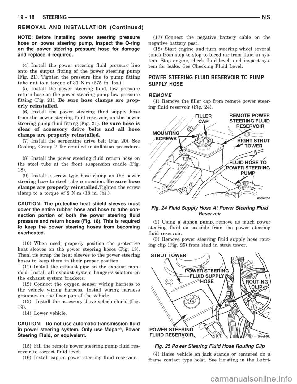
(1) Remove the filler cap from remote power steer-
ing fluid reservoir (Fig. 24).
(2) Using a siphon pump, remove as much power
steering fluid as possible from the power steering
fluid reservoir.
(3) Remove power steering fluid supply hose rout-
ing clip (Fig. 25) from stud in strut tower.
(4) Raise vehicle on jack stands or centered on a
frame contact type hoist. See Hoisting in the Lubri-
Fig. 24 Fluid Supply Hose At Power Steering Fluid
Reservoir
Fig. 25 Power Steering Fluid Hose Routing Clip
19 - 18 STEERINGNS
REMOVAL AND INSTALLATION (Continued)
Page 1445 of 1938
cation and Maintenance section of this service man-
ual, for the required lifting procedure to be used for
this vehicle.
(5) Remove at power steering pump, the power
steering fluid hose coming from the power steering
fluid reservoir. Let the power steering fluid drain out
of the reservoir and hose.
(6) Lower vehicle.
(7) Remove hose clamp attaching the power steer-
ing fluid supply hose to the power steering fluid res-
ervoir (Fig. 24).
(8) Remove the power steering fluid supply hose
from the vehicle. Hose is removed from the top of the
engine compartment.
INSTALL
CAUTION: On V-6 engine applications, the power
steering fluid reservoir to power steering hose must
be routed tightly against the strut tower and parallel
to the dash panel. It must also be routed under the
wiring harness and below the drip tube. This rout-
ing will prevent the power steering fluid supply
hose from coming in contact with the accessory
drive belt.
(1) Install and correctly route the power steering
fluid supply hose from remote fluid reservoir down to
power steering pump.
(2) Install the fluid supply hose onto the power
steering fluid reservoir (Fig. 24). Install the hose
clamp on the fluid supply hose.Be sure hose clamp
is installed past bead on fluid reservoir fitting.
(3) Raise vehicle on jack stands or centered on a
frame contact type hoist. See Hoisting in the Lubri-
cation and Maintenance section of this service man-
ual, for the required lifting procedure to be used for
this vehicle.
(4) Install power steering fluid supply hose on
power steering pump. Install the hose clamp on the
fluid supply hose.Be sure hose clamp is installed
past bead on pump fitting.
(5) Lower vehicle.
(6) Install routing clip on power steering fluid sup-
ply hose. Be sure routing clip is installed in a posi-
tion to correctly align with stud in strut tower.
(7) Install routing clip for power steering fluid sup-
ply hose on stud in strut tower (Fig. 25).
(8) Fill the remote fluid reservoir to the proper
level and let the fluid settle for at least two (2) min-
utes.
(9) Start the engine and let run for a few seconds.
Then turn the engine off.
(10) Add fluid if necessary. Repeat the above pro-
cedure until the fluid level remains constant after
running the engine.
(11) Raise the front wheels off the ground.(12) Start the engine. Slowly turn the steering
wheel right and left, lightly contacting the wheel
stops.
(13) Add power steering fluid if necessary.
(14) Lower the vehicle and turn the steering wheel
slowly from lock to lock.
(15) Stop the engine. Check the fluid level and
refill as required.
(16) If the fluid is extremely foamy, allow the vehi-
cle to stand a few minutes and repeat the above pro-
cedure.
POWER STEERING FLUID PRESSURE HOSE
Service all power steering hoses with vehicle raised
on hoist. Cap all open ends of hoses, power steering
pump fittings and steering gear ports to prevent
entry of foreign material into the components.
WARNING: POWER STEERING OIL, ENGINE
PARTS AND THE EXHAUST SYSTEM MAY BE
EXTREMELY HOT IF ENGINE HAS BEEN RUNNING.
DO NOT START ENGINE WITH ANY LOOSE OR DIS-
CONNECTED HOSES. DO NOT ALLOW HOSES TO
TOUCH HOT EXHAUST MANIFOLD OR CATALYST.
For part reference and part location for the vehicle
that is being serviced, refer to the following figure
numbers. These show the hose bracket locations,
hose routings and fitting locations by the engine
application of the vehicle. Use these figure numbers
when referring to the removal or installation proce-
dures for the power steering hoses listed below.
REMOVE
(1) Remove cap from power steering fluid reser-
voir.
(2) Using a siphon pump, remove as much power
steering fluid as possible from the power steering
fluid reservoir.
(3) Raise vehicle See Hoisting, Group 0. Put oil
drain pan under vehicle to catch power steering fluid.
(4) Raise the heat sleeve on the power steering
fluid return hose (Fig. 26) to expose the return hose
to steel tube connection. Remove the hose clamp from
the power steering fluid return hose (Fig. 26).
Remove power steering fluid return hose from steel
tube and allow power steering fluid to drain from
pump.
NSSTEERING 19 - 19
REMOVAL AND INSTALLATION (Continued)
Page 1448 of 1938
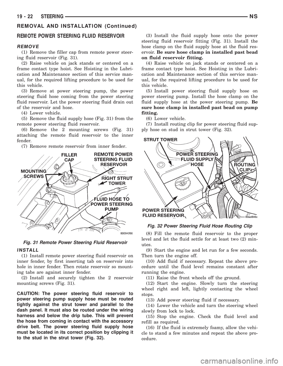
REMOTE POWER STEERING FLUID RESERVOIR
REMOVE
(1) Remove the filler cap from remote power steer-
ing fluid reservoir (Fig. 31).
(2) Raise vehicle on jack stands or centered on a
frame contact type hoist. See Hoisting in the Lubri-
cation and Maintenance section of this service man-
ual, for the required lifting procedure to be used for
this vehicle.
(3) Remove at power steering pump, the power
steering fluid hose coming from the power steering
fluid reservoir. Let the power steering fluid drain out
of the reservoir and hose.
(4) Lower vehicle.
(5) Remove the fluid supply hose (Fig. 31) from the
remote power steering fluid reservoir.
(6) Remove the 2 mounting screws (Fig. 31)
attaching the remote fluid reservoir to the inner
fender.
(7) Remove remote reservoir from inner fender.
INSTALL
(1) Install remote power steering fluid reservoir on
inner fender, by first inserting tab on reservoir into
hole in inner fender. Then rotate reservoir so mount-
ing tabs are against inner fender.
(2) Install and securely tighten the 2 reservoir
mounting screws (Fig. 31).
CAUTION: The power steering fluid reservoir to
power steering pump supply hose must be routed
tightly against the strut tower and parallel to the
dash panel. It must also be routed under the wiring
harness and below the drip tube. This will prevent
the hose from coming in contact with the accessory
drive belt. The power steering fluid supply hose
must be located in its correct position by clipping it
to the stud in the strut tower (Fig. 32).(3) Install the fluid supply hose onto the power
steering fluid reservoir fitting (Fig. 31). Install the
hose clamp on the fluid supply hose at the fluid res-
ervoir.Be sure hose clamp in installed past bead
on fluid reservoir fitting.
(4) Raise vehicle on jack stands or centered on a
frame contact type hoist. See Hoisting in the Lubri-
cation and Maintenance section of this service man-
ual, for the required lifting procedure to be used for
this vehicle.
(5) Install power steering fluid supply hose on
power steering pump. Install the hose clamp on the
fluid supply hose at the power steering pump.Be
sure hose clamp in installed past bead on pump
fitting.
(6) Lower vehicle.
(7) Install routing clip for power steering fluid sup-
ply hose on stud in strut tower (Fig. 32).
(8) Fill the remote fluid reservoir to the proper
level and let the fluid settle for at least two (2) min-
utes.
(9) Start the engine and let run for a few seconds.
Then turn the engine off.
(10) Add fluid if necessary. Repeat the above pro-
cedure until the fluid level remains constant after
running the engine.
(11) Raise the front wheels off the ground.
(12) Start the engine. Slowly turn the steering
wheel right and left, lightly contacting the wheel
stops.
(13) Add power steering fluid if necessary.
(14) Lower the vehicle and turn the steering wheel
slowly from lock to lock.
(15) Stop the engine. Check the fluid level and
refill as required.
(16) If the fluid is extremely foamy, allow the vehi-
cle to stand a few minutes and repeat the above pro-
cedure.
Fig. 31 Remote Power Steering Fluid Reservoir
Fig. 32 Power Steering Fluid Hose Routing Clip
19 - 22 STEERINGNS
REMOVAL AND INSTALLATION (Continued)