stop start CHRYSLER VOYAGER 1996 Workshop Manual
[x] Cancel search | Manufacturer: CHRYSLER, Model Year: 1996, Model line: VOYAGER, Model: CHRYSLER VOYAGER 1996Pages: 1938, PDF Size: 55.84 MB
Page 1831 of 1938
be 21ÉC to 27ÉC (70ÉF to 85ÉF). To test the expansion
valve:
NOTE: Liquid CO2 is required to test the expansion
valve. It is available from most welding supply facil-
ities. CO2 is also available from companies which
service and sell fire extinguishers.
(1) Connect a charging station or manifold gauge
set to the refrigerant system service ports. Verify the
refrigerant charge level.
(2) Close all doors, windows and vents to the pas-
senger compartment.
(3) Set heater A/C control to A/C, full heat,
FLOOR, and high blower.
(4) Start the engine and allow to idle (1000 rpm).
After the engine has reached running temperature,
allow the passenger compartment to heat up. This
will create the need for maximum refrigerant flow
into the evaporator.
(5) If the refrigerant charge is sufficient, discharge
(high pressure) gauge should read 965 to 1655 kPa
(140 to 240 psi). Suction (low pressure) gauge should
read 140 kPa to 207 kPa (20 psi to 30 psig). If system
cannot achieve proper pressure readings, replace the
expansion valve. If pressure is correct, proceed with
test.
WARNING: PROTECT SKIN AND EYES FROM CON-
TACTING CO2 PERSONAL INJURY CAN RESULT.
(6) If suction side low pressure is within specified
range, freeze the expansion valve control head for 30
seconds. Use a super cold substance (liquid CO2).Do
not spray R-134a or R-12 Refrigerant on the
expansion valve for this test.Suction side low
pressure should drop by 10 psi. If not, replace expan-
sion valve.
(7) Allow expansion valve to thaw. The low pres-
sure gauge reading should stabilize at 140 kPa to
240 kPa (20 psi to 30 psig). If not, replace expansion
valve.
(8) When expansion valve test is complete, test
A/C overall performance. Remove all test equipment
before returning vehicle to use.
HEATER PERFORMANCE TEST
PRE-DIAGNOSTIC PREPARATIONS
Review Safety Precautions and Warnings in this
group before performing the following procedures.
Check the coolant level, drive belt tension, vacuum
line connections, radiator air flow and fan operation.
Start engine and allow to warm up to normal tem-
perature.WARNING: DO NOT REMOVE RADIATOR CAP
WHEN ENGINE IS HOT, PERSONAL INJURY CAN
RESULT.
If vehicle has been run recently, wait 15 minutes
before removing cap. Place a rag over the cap and
turn it to the first safety stop. Allow pressure to
escape through the overflow tube. When the system
stabilizes, remove the cap completely.
MAXIMUM HEATER OUTPUT: TEST AND
ACTION
Engine coolant is provided to the heater system by
two 16 mm (5/8 inch inside diameter) heater hoses.
With engine idling at normal running temperature,
set the control to maximum heat, floor, and high
blower setting. Using a test thermometer, check the
air temperature coming from the floor outlets, refer
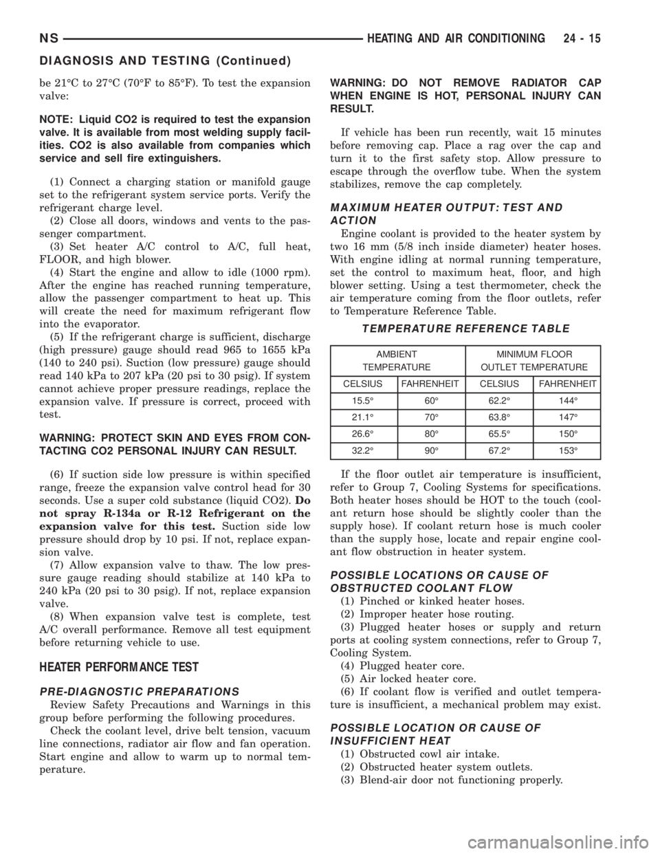
to Temperature Reference Table.
If the floor outlet air temperature is insufficient,
refer to Group 7, Cooling Systems for specifications.
Both heater hoses should be HOT to the touch (cool-
ant return hose should be slightly cooler than the
supply hose). If coolant return hose is much cooler
than the supply hose, locate and repair engine cool-
ant flow obstruction in heater system.
POSSIBLE LOCATIONS OR CAUSE OF
OBSTRUCTED COOLANT FLOW
(1) Pinched or kinked heater hoses.
(2) Improper heater hose routing.
(3) Plugged heater hoses or supply and return
ports at cooling system connections, refer to Group 7,
Cooling System.
(4) Plugged heater core.
(5) Air locked heater core.
(6) If coolant flow is verified and outlet tempera-
ture is insufficient, a mechanical problem may exist.
POSSIBLE LOCATION OR CAUSE OF
INSUFFICIENT HEAT
(1) Obstructed cowl air intake.
(2) Obstructed heater system outlets.
(3) Blend-air door not functioning properly.
TEMPERATURE REFERENCE TABLE
AMBIENT
TEMPERATUREMINIMUM FLOOR
OUTLET TEMPERATURE
CELSIUS FAHRENHEIT CELSIUS FAHRENHEIT
15.5É 60É 62.2É 144É
21.1É 70É 63.8É 147É
26.6É 80É 65.5É 150É
32.2É 90É 67.2É 153É
NSHEATING AND AIR CONDITIONING 24 - 15
DIAGNOSIS AND TESTING (Continued)
Page 1834 of 1938
NOTE: When connecting the service equipment
coupling to the line fitting, verify that the valve of
the coupling is fully closed. This will reduce the
amount of effort required to make the connection.
(1) Connect manifold gauge set.
(2) Measure refrigerant (refer to capacities) and
heat to 52ÉC (125ÉF) with the charging station. Refer
to the instructions provided with the equipment
being used.
REFRIGERANT CAPACITIES
²Without Rear A/C = .96 kg (34 oz. or 2.13lb.)
²With Rear A/C = 1.36 kg (48 oz. or 3.00 lb.)
(3) Open the suction and discharge valves. Open
the charge valve to allow the heated refrigerant to
flow into the system. When the transfer of refriger-
ant has stopped, close the suction and discharge
valve.
(4) If all of the charge did not transfer from the
dispensing device, run engine at a high idle (1400
rpm). Set the A/C control to A/C, low blower speed,
and open windows. If the A/C compressor does not
engage, test the compressor clutch control circuit and
correct any failure. Refer to Group 8W, Wiring Dia-
grams.
(5) Open the suction valve to allow the remaining
refrigerant to transfer to the system.
WARNING: TAKE CARE NOT TO OPEN THE DIS-
CHARGE (HIGH-PRESSURE) VALVE AT THIS TIME.(6) Close all valves and test the A/C system perfor-
mance.
(7) Disconnect the charging station or manifold
gauge set. Install the service port caps.
EVACUATING REFRIGERANT SYSTEM
NOTE: Special effort must be used to prevent mois-
ture from entering the A/C system oil. Moisture in
the oil is very difficult to remove and will cause a
reliability problem with the compressor.
If a compressor designed to use R-134a refrigerant
is left open to the atmosphere for an extended period
of time. It is recommended that the refrigerant oil be
drained and replaced with new oil or a new compres-
sor be used. This will eliminate the possibility of con-
taminating the refrigerant system.
If the refrigerant system has been open to the
atmosphere, it must be evacuated before the system
can be filled. Moisture and air mixed with the refrig-
erant will raise the compressor head pressure above
acceptable operating levels. This will reduce the per-
formance of the air conditioner and damage the com-
pressor. Moisture will boil at near room temperature
when exposed to vacuum. To evacuate the refrigerant
system:
NOTE: When connecting the service equipment
coupling to the line fitting, verify that the valve of
the coupling is fully closed. This will reduce the
amount of effort required to make the connection.
(1) Connect a suitable charging station, refrigerant
recovery machine, and a manifold gauge set with
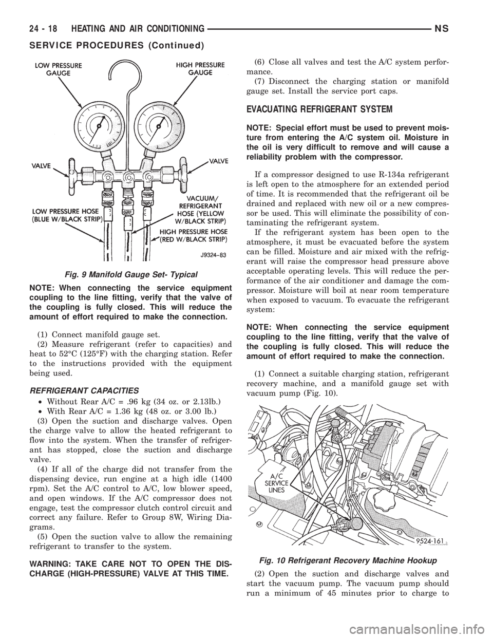
vacuum pump (Fig. 10).
(2) Open the suction and discharge valves and
start the vacuum pump. The vacuum pump should
run a minimum of 45 minutes prior to charge to
Fig. 9 Manifold Gauge Set- Typical
Fig. 10 Refrigerant Recovery Machine Hookup
24 - 18 HEATING AND AIR CONDITIONINGNS
SERVICE PROCEDURES (Continued)
Page 1873 of 1938
COOLDOWN TEST ENTRY
TO INITIATE TESTS:
²Set Blower motor ON HIGH
²Set Mode position to Panel
²Open all A/C outlets
²Set Temperature to Cold (Both slide pots if
equipped)
²Depress WASH and A/C simultaneously for 5
Seconds
NOTE: Prior to start of test, If the evaporator is
already cold, the system will fail test. To correct,
operate system with A/C OFF and the blower motor
ON high for three minutes prior to starting test.
RESULTS:
²All LED's will turn on for 5 Seconds
²Cooldown Test is running when A/C and
RECIRC. are alternately flashing. If A/C and
RECIRC. are flashing simultaneously, Cooldown has
failed.
CALIBRATION DIAGNOSTICS AND
COOLDOWN ABORT
Test can be aborted by doing one of the following:
²Depressing Rear Window Defogger, RECIRC and
Rear Wiper buttons.²Cycling Ignition OFF and then ON.
²Control will automatically abort after 15 min-
utes from the time Calibration Diagnostics and
Cooldown was entered.
The HVAC control module will return to normal
operation or may indicate unsuccessful Calibration
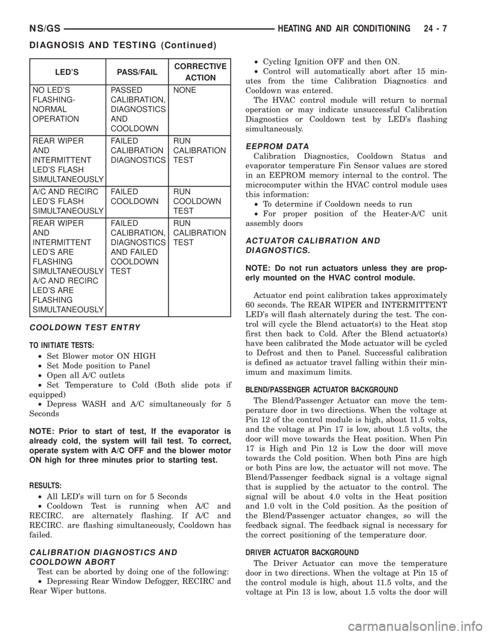
Diagnostics or Cooldown test by LED's flashing
simultaneously.
EEPROM DATA
Calibration Diagnostics, Cooldown Status and
evaporator temperature Fin Sensor values are stored
in an EEPROM memory internal to the control. The
microcomputer within the HVAC control module uses
this information:
²To determine if Cooldown needs to run
²For proper position of the Heater-A/C unit
assembly doors
ACTUATOR CALIBRATION AND
DIAGNOSTICS.
NOTE: Do not run actuators unless they are prop-
erly mounted on the HVAC control module.
Actuator end point calibration takes approximately
60 seconds. The REAR WIPER and INTERMITTENT
LED's will flash alternately during the test. The con-
trol will cycle the Blend actuator(s) to the Heat stop
first then back to Cold. After the Blend actuator(s)
have been calibrated the Mode actuator will be cycled
to Defrost and then to Panel. Successful calibration
is defined as actuator travel falling within their min-
imum and maximum limits.
BLEND/PASSENGER ACTUATOR BACKGROUND
The Blend/Passenger Actuator can move the tem-
perature door in two directions. When the voltage at
Pin 12 of the control module is high, about 11.5 volts,
and the voltage at Pin 17 is low, about 1.5 volts, the
door will move towards the Heat position. When Pin
17 is High and Pin 12 is Low the door will move
towards the Cold position. When both Pins are high
or both Pins are low, the actuator will not move. The
Blend/Passenger feedback signal is a voltage signal
that is supplied by the actuator to the control. The
signal will be about 4.0 volts in the Heat position
and 1.0 volt in the Cold position. As the position of
the Blend/Passenger actuator changes, so will the
feedback signal. The feedback signal is necessary for
the correct positioning of the temperature door.
DRIVER ACTUATOR BACKGROUND
The Driver Actuator can move the temperature
door in two directions. When the voltage at Pin 15 of
the control module is high, about 11.5 volts, and the
voltage at Pin 13 is low, about 1.5 volts the door will
LED'S PASS/FAILCORRECTIVE
ACTION
NO LED'S
FLASHING-
NORMAL
OPERATIONPASSED
CALIBRATION,
DIAGNOSTICS
AND
COOLDOWNNONE
REAR WIPER
AND
INTERMITTENT
LED'S FLASH
SIMULTANEOUSLYFAILED
CALIBRATION
DIAGNOSTICSRUN
CALIBRATION
TEST
A/C AND RECIRC
LED'S FLASH
SIMULTANEOUSLYFAILED
COOLDOWNRUN
COOLDOWN
TEST
REAR WIPER
AND
INTERMITTENT
LED'S ARE
FLASHING
SIMULTANEOUSLY
A/C AND RECIRC
LED'S ARE
FLASHING
SIMULTANEOUSLYFAILED
CALIBRATION,
DIAGNOSTICS
AND FAILED
COOLDOWN
TESTRUN
CALIBRATION
TEST
NS/GSHEATING AND AIR CONDITIONING 24 - 7
DIAGNOSIS AND TESTING (Continued)
Page 1880 of 1938
(6) If coil current reads zero, the coil is open and
should be replaced. If the ammeter reading is 4
amperes or more, the coil is shorted and should be
replaced. If the coil voltage is not within two volts of
the battery voltage, test clutch coil feed circuit for
excessive voltage drop.
EXPANSION VALVE
NOTE: Special effort must be used to keep all
R-134a system components moisture-free. Moisture
in the oil is very difficult to remove and will cause a
reliability problem with the compressor.
TESTS
NOTE: Expansion valve tests should be performed
after compressor tests.
Review Safety Precautions and Warnings in this
group. The work area and vehicle temperature must
be 21ÉC to 27ÉC (70ÉF to 85ÉF). To test the expansion
valve:
NOTE: Liquid CO2 is required to test the expansion
valve. It is available from most welding supply facil-
ities. CO2 is also available from companies which
service and sell fire extinguishers.
(1) Connect a charging station or manifold gauge
set to the refrigerant system service ports. Verify the
refrigerant charge level.
(2) Close all doors, windows and vents to the pas-
senger compartment.
(3) Set heater A/C control to A/C, full heat,
FLOOR, and high blower.
(4) Start the engine and allow to idle (1000 rpm).
After the engine has reached running temperature,
allow the passenger compartment to heat up. This
will create the need for maximum refrigerant flow
into the evaporator.
(5) I
f the refrigerant charge is sufficient, discharge
(high pressure) gauge should read 965 to 1655 kPa (140
to 240 psi). Suction (low pressure) gauge should read
140 kPa to 207 kPa (20 psi to 30 psig). If system cannot
achieve proper pressure readings, replace the expan-
sion valve. If pressure is correct, proceed with test.
WARNING: PROTECT SKIN AND EYES FROM CON-
TACTING CO2 PERSONAL INJURY CAN RESULT.
(6) If suction side low pressure is within specified
range, freeze the expansion valve control head for 30
seconds. Use a super cold substance (liquid CO2).Do
not spray R-134a Refrigerant on the expansion
valve for this test.Suction side low pressure should
drop by 10 psi. If not, replace expansion valve.(7) Allow expansion valve to thaw. The low pres-
sure gauge reading should stabilize at 140 kPa to
240 kPa (20 psi to 30 psig). If not, replace expansion
valve.
(8) When expansion valve test is complete, test
A/C overall performance. Remove all test equipment
before returning vehicle to use.
HEATER PERFORMANCE TEST
PRE-DIAGNOSTIC PREPARATIONS
Review Safety Precautions and Warnings in this
group before performing the following procedures.
Check the coolant level, drive belt tension, vacuum
line connections, radiator air flow and fan operation.
Start engine and allow to warm up to normal tem-
perature.
WARNING: DO NOT REMOVE RADIATOR CAP
WHEN ENGINE IS HOT, PERSONAL INJURY CAN
RESULT.
If vehicle has been run recently, wait 15 minutes
before removing cap. Place a rag over the cap and
turn it to the first safety stop. Allow pressure to
escape through the overflow tube. When the system
stabilizes, remove the cap completely.
MAXIMUM HEATER OUTPUT: TEST AND
ACTION
Engine coolant is provided to the heater system by
two 16 mm (5/8 inch inside diameter) heater hoses.
With engine idling at normal running temperature,
set the control to maximum heat, floor, and high
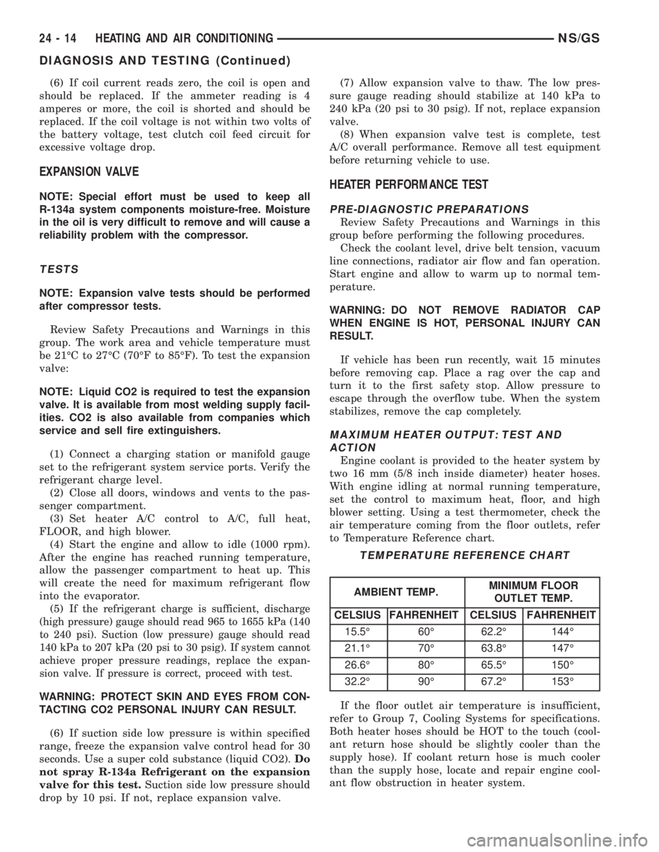
blower setting. Using a test thermometer, check the
air temperature coming from the floor outlets, refer
to Temperature Reference chart.
If the floor outlet air temperature is insufficient,
refer to Group 7, Cooling Systems for specifications.
Both heater hoses should be HOT to the touch (cool-
ant return hose should be slightly cooler than the
supply hose). If coolant return hose is much cooler
than the supply hose, locate and repair engine cool-
ant flow obstruction in heater system.
TEMPERATURE REFERENCE CHART
AMBIENT TEMP.MINIMUM FLOOR
OUTLET TEMP.
CELSIUS FAHRENHEIT CELSIUS FAHRENHEIT
15.5É 60É 62.2É 144É
21.1É 70É 63.8É 147É
26.6É 80É 65.5É 150É
32.2É 90É 67.2É 153É
24 - 14 HEATING AND AIR CONDITIONINGNS/GS
DIAGNOSIS AND TESTING (Continued)
Page 1883 of 1938
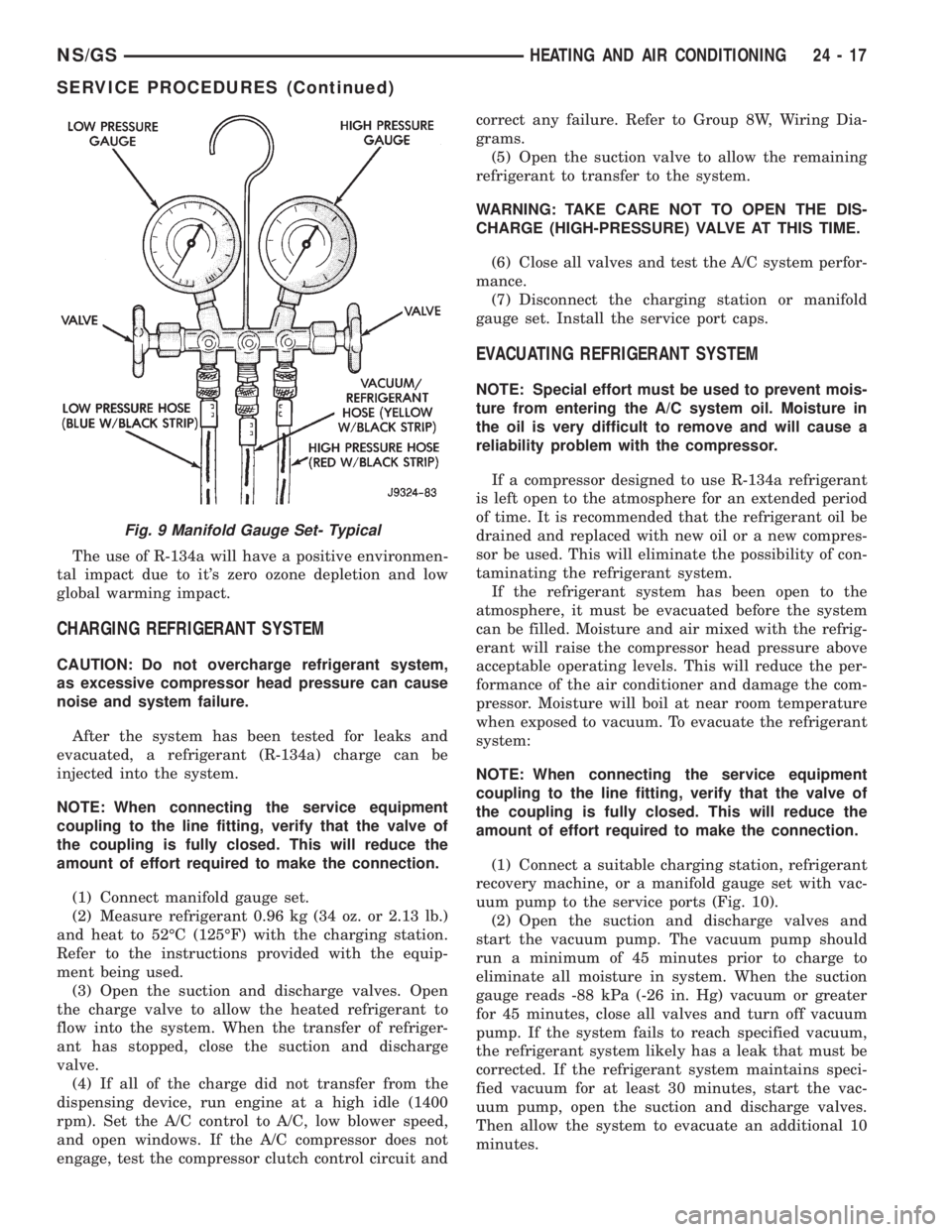
The use of R-134a will have a positive environmen-
tal impact due to it's zero ozone depletion and low
global warming impact.
CHARGING REFRIGERANT SYSTEM
CAUTION: Do not overcharge refrigerant system,
as excessive compressor head pressure can cause
noise and system failure.
After the system has been tested for leaks and
evacuated, a refrigerant (R-134a) charge can be
injected into the system.
NOTE: When connecting the service equipment
coupling to the line fitting, verify that the valve of
the coupling is fully closed. This will reduce the
amount of effort required to make the connection.
(1) Connect manifold gauge set.
(2) Measure refrigerant 0.96 kg (34 oz. or 2.13 lb.)
and heat to 52ÉC (125ÉF) with the charging station.
Refer to the instructions provided with the equip-
ment being used.
(3) Open the suction and discharge valves. Open
the charge valve to allow the heated refrigerant to
flow into the system. When the transfer of refriger-
ant has stopped, close the suction and discharge
valve.
(4) If all of the charge did not transfer from the
dispensing device, run engine at a high idle (1400
rpm). Set the A/C control to A/C, low blower speed,
and open windows. If the A/C compressor does not
engage, test the compressor clutch control circuit andcorrect any failure. Refer to Group 8W, Wiring Dia-
grams.
(5) Open the suction valve to allow the remaining
refrigerant to transfer to the system.
WARNING: TAKE CARE NOT TO OPEN THE DIS-
CHARGE (HIGH-PRESSURE) VALVE AT THIS TIME.
(6) Close all valves and test the A/C system perfor-
mance.
(7) Disconnect the charging station or manifold
gauge set. Install the service port caps.
EVACUATING REFRIGERANT SYSTEM
NOTE: Special effort must be used to prevent mois-
ture from entering the A/C system oil. Moisture in
the oil is very difficult to remove and will cause a
reliability problem with the compressor.
If a compressor designed to use R-134a refrigerant
is left open to the atmosphere for an extended period
of time. It is recommended that the refrigerant oil be
drained and replaced with new oil or a new compres-
sor be used. This will eliminate the possibility of con-
taminating the refrigerant system.
If the refrigerant system has been open to the
atmosphere, it must be evacuated before the system
can be filled. Moisture and air mixed with the refrig-
erant will raise the compressor head pressure above
acceptable operating levels. This will reduce the per-
formance of the air conditioner and damage the com-
pressor. Moisture will boil at near room temperature
when exposed to vacuum. To evacuate the refrigerant
system:
NOTE: When connecting the service equipment
coupling to the line fitting, verify that the valve of
the coupling is fully closed. This will reduce the
amount of effort required to make the connection.
(1) Connect a suitable charging station, refrigerant
recovery machine, or a manifold gauge set with vac-
uum pump to the service ports (Fig. 10).
(2) Open the suction and discharge valves and
start the vacuum pump. The vacuum pump should
run a minimum of 45 minutes prior to charge to
eliminate all moisture in system. When the suction
gauge reads -88 kPa (-26 in. Hg) vacuum or greater
for 45 minutes, close all valves and turn off vacuum
pump. If the system fails to reach specified vacuum,
the refrigerant system likely has a leak that must be
corrected. If the refrigerant system maintains speci-
fied vacuum for at least 30 minutes, start the vac-
uum pump, open the suction and discharge valves.
Then allow the system to evacuate an additional 10
minutes.
Fig. 9 Manifold Gauge Set- Typical
NS/GSHEATING AND AIR CONDITIONING 24 - 17
SERVICE PROCEDURES (Continued)
Page 1914 of 1938
The primary components within the assembly are:
A three port solenoid that activates both of the func-
tions listed above; a pump which contains a switch,
two check valves and a spring/diaphragm, a canister
vent valve (CVV) seal which contains a spring loaded
vent seal valve.
Immediately after a cold start, between predeter-
mined temperature thresholds limits, the three port
solenoid is briefly energized. This initializes the
pump by drawing air into the pump cavity and also
closes the vent seal. During non test conditions the
vent seal is held open by the pump diaphragm
assembly which pushes it open at the full travel posi-
tion. The vent seal will remain closed while the
pump is cycling due to the reed switch triggering of
the three port solenoid that prevents the diaphragm
assembly from reaching full travel. After the brief
initialization period, the solenoid is de-energized
allowing atmospheric pressure to enter the pump
cavity, thus permitting the spring to drive the dia-
phragm which forces air out of the pump cavity and
into the vent system. When the solenoid is energized
and de energized, the cycle is repeated creating flow
in typical diaphragm pump fashion. The pump is con-
trolled in 2 modes:
Pump Mode:The pump is cycled at a fixed rate to
achieve a rapid pressure build in order to shorten the
overall test length.
Test Mode:The solenoid is energized with a fixed
duration pulse. Subsequent fixed pulses occur when
the diaphragm reaches the Switch closure point.
The spring in the pump is set so that the system
will achieve an equalized pressure of about 7.5º H20.
The cycle rate of pump strokes is quite rapid as the
system begins to pump up to this pressure. As the
pressure increases, the cycle rate starts to drop off. If
there is no leak in the system, the pump would even-
tually stop pumping at the equalized pressure. If
there is a leak, it will continue to pump at a rate rep-
resentative of the flow characteristic of the size of the
leak. From this information we can determine if the
leak is larger than the required detection limit (cur-
rently set at .020º orifice by CARB). If a leak is
revealed during the leak test portion of the test, the
test is terminated at the end of the test mode and no
further system checks will be performed.
After passing the leak detection phase of the test,
system pressure is maintained by turning on the
LDP's solenoid until the purge system is activated.
Purge activation in effect creates a leak. The cycle
rate is again interrogated and when it increases due
to the flow through the purge system, the leak check
portion of the diagnostic is complete.
The canister vent valve will unseal the system
after completion of the test sequence as the pumpdiaphragm assembly moves to the full travel position.
Evaporative system functionality will be verified by
using the stricter evap purge flow monitor. At an
appropriate warm idle the LDP will be energized to
seal the canister vent. The purge flow will be clocked
up from some small value in an attempt to see a
shift in the 02 control system. If fuel vapor, indicated
by a shift in the 02 control, is present the test is
passed. If not, it is assumed that the purge system is
not functioning in some respect. The LDP is again
turned off and the test is ended.
TRIP DEFINITION
A ªTripº means vehicle operation (following an
engine-off period) of duration and driving mode such
that all components and systems are monitored at
least once by the diagnostic system. The monitors
must successfully pass before the PCM can verify
that a previously malfunctioning component is meet-
ing the normal operating conditions of that compo-
nent. For misfire or fuel system malfunction, the
MIL may be extinguished if the fault does not recur
when monitored during three subsequent sequential
driving cycles in which conditions are similar to
those under which the malfunction was first deter-
mined.
Anytime the MIL is illuminated, a DTC is stored.
The DTC can self erase only when the MIL has been
extinguished. Once the MIL is extinguished, the
PCM must pass the diagnostic test for the most
recent DTC for 40 warm-up cycles (80 warm-up
cycles for the Fuel System Monitor and the Misfire
Monitor). A warm-up cycle can best be described by
the following:
²The engine must be running
²A rise of 40ÉF in engine temperature must occur
from the time when the engine was started
²Engine coolant temperature must reach at least
160ÉF
²A ªdriving cycleº that consists of engine start up
and engine shut off.
Once the above conditions occur, the PCM is con-
sidered to have passed a warm-up cycle. Due to the
conditions required to extinguish the MIL and erase
the DTC, it is most important that after a repair has
been made, all DTC's be erased and the repair veri-
fied.
COMPONENT MONITORS
There are several components that will affect vehi-
cle emissions if they malfunction. If one of these com-
ponents malfunctions the Malfunction Indicator
Lamp (Check Engine) will illuminate.
Some of the component monitors are checking for
proper operation of the part. Electrically operated
25 - 10 EMISSION CONTROL SYSTEMSNS
DESCRIPTION AND OPERATION (Continued)
Page 1931 of 1938
Generic Scan
Tool CodeDRB III Scan Tool Display
P0725 Engine Speed Sensor Dynamic Plausibility
Engine Speed Sensor Over Speed Recognition
Engine Speed Sensor Static Plausibilty
P1105 Atmospheric Pressure Sensor SRC High Exceeded
Atmospheric Pressure Sensor SRC Low Exceeded
P1201 Needle Movement Sensor SRC High Exceeded
Needle Movement Sensor SRC Low Exceeded
P1220 Fuel Quantity Actuator Neg. Gov. Deviation Cold
Fuel Quantity Actuator Neg. Gov. Deviation Warm
Fuel Quantity Actuator Pos. Gov. Deviation Cold
Fuel Quantity Actuator Pos. Gov. Deviation Warm
P1225 Control Sleeve Sensor Signal High Exceeded
Control Sleeve Sensor Start End Pos. Not Attained
Control Sleeve Sensor Stop End Pos. Not Attained
P1230 Timing Governing Negative Governor Deviation
Timing Governing Positive Governor Deviation
P1515 Accelerator Pedal Sensor Signal High Exceeded
Accelerator Pedal Sensor Signal Low Exceeded
Accelerator Pedal Sensor Signal PWG Plaus With Low Idle Switch
Accelerator Pedal Sensor Signal PWG Plaus With Potentiometer
P1600 Battery Voltage SRC High Exceeded
P1605 Terminal #15 Plausibility After Startup
P1610 Regulator Lower Regulator Limit
Regulator Upper Regulator Limit
P1615 Microcontroller Gate-Array Monitoring
Microcontroller Gate-Array Watchdog
Microcontroller Prepare Fuel Quantity Stop
Microcontroller Recovery Was Occurred
Microcontrller Redundant Overrun Monitoring
P1630 Timing Solenoid Valve Controller Open Circuit
Timing Solenoid Valve Controller Short Circuit
P1635 Glow Relay Controller Open Circuit
Glow Relay Controller Short Circuit
P1650 Diagnostic Lamp Open Circuit
Diagnostic Lamp Short Circuit
P1655 A/C Control Short Circuit
A/C Control Open Circuit
P1660 Redundant Emer. Stop Plausibility In After-Run
Redundant Emer Stop Powerstage Defective
P1665 Cruise Status Indicator Lamp Short Circuit
P1680 EEPROM Plausibility Checksum Error for Adj.
EEPROM Plausibility Checksum Error in CC212
EEPROM Plausibility Communication With EEPROM
EEPROM Plausibility Func. Switch Wrong or Missing
NS/GSEMISSION CONTROL SYSTEM 25 - 3
DESCRIPTION AND OPERATION (Continued)