stop start CHRYSLER VOYAGER 1996 Owner's Guide
[x] Cancel search | Manufacturer: CHRYSLER, Model Year: 1996, Model line: VOYAGER, Model: CHRYSLER VOYAGER 1996Pages: 1938, PDF Size: 55.84 MB
Page 1453 of 1938
The drive tangs on the pinion mate loosely with a
stub shaft to permit manual steering control to be
maintained if the drive belt on the power steering
pump should break. However, under these conditions,
steering effort will be increased.
DIAGNOSIS AND TESTING
POWER STEERING GEAR
The following procedure can be used to test the
operation of the power steering system on this vehi-
cle. This test will provide the flow rate for the power
steering system along with the maximum relief pres-
sure of the power steering pump. This test is to be
performed any time a power steering system problem
is present to determine if the power steering pump or
power steering gear is not functioning properly. The
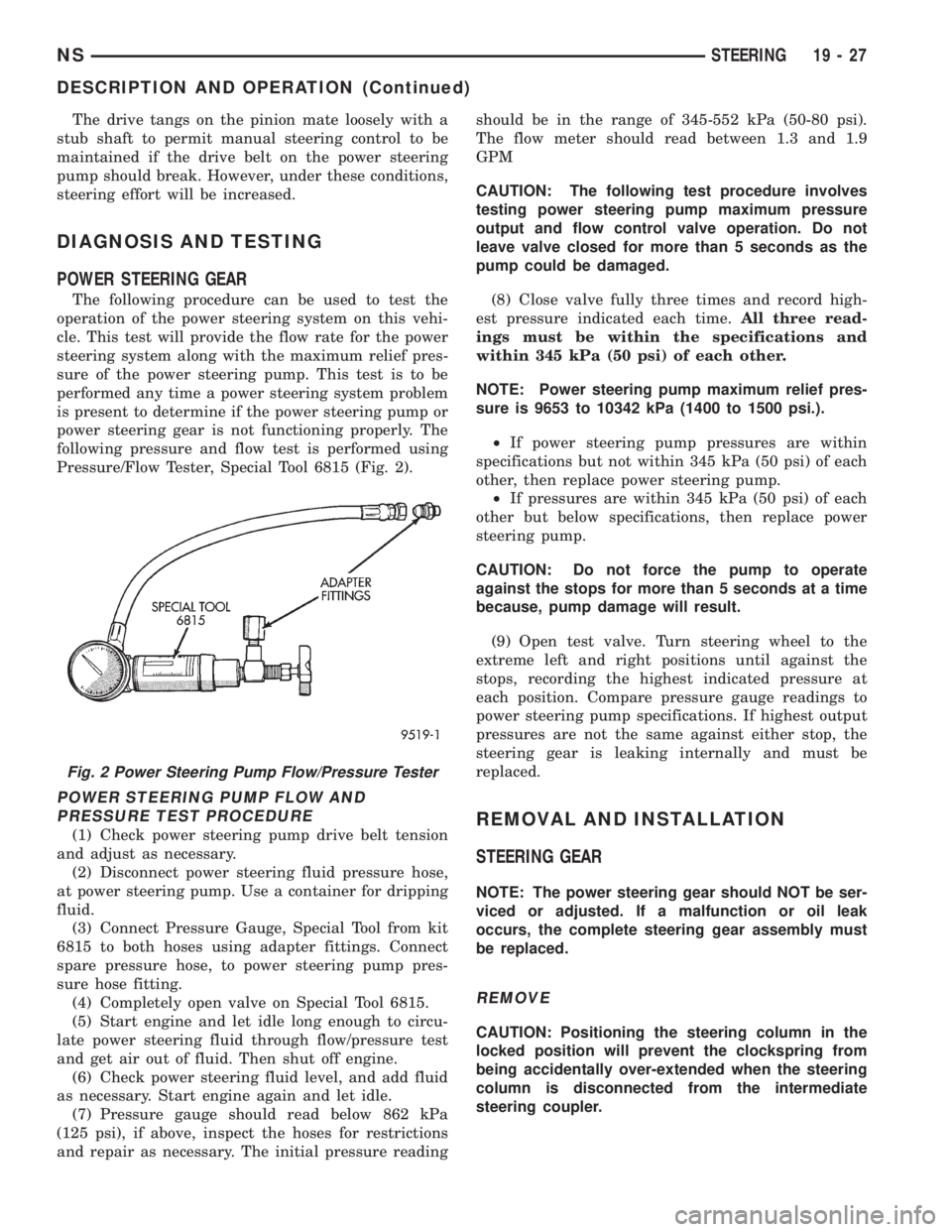
following pressure and flow test is performed using
Pressure/Flow Tester, Special Tool 6815 (Fig. 2).
POWER STEERING PUMP FLOW AND
PRESSURE TEST PROCEDURE
(1) Check power steering pump drive belt tension
and adjust as necessary.
(2) Disconnect power steering fluid pressure hose,
at power steering pump. Use a container for dripping
fluid.
(3) Connect Pressure Gauge, Special Tool from kit
6815 to both hoses using adapter fittings. Connect
spare pressure hose, to power steering pump pres-
sure hose fitting.
(4) Completely open valve on Special Tool 6815.
(5) Start engine and let idle long enough to circu-
late power steering fluid through flow/pressure test
and get air out of fluid. Then shut off engine.
(6) Check power steering fluid level, and add fluid
as necessary. Start engine again and let idle.
(7) Pressure gauge should read below 862 kPa
(125 psi), if above, inspect the hoses for restrictions
and repair as necessary. The initial pressure readingshould be in the range of 345-552 kPa (50-80 psi).
The flow meter should read between 1.3 and 1.9
GPM
CAUTION: The following test procedure involves
testing power steering pump maximum pressure
output and flow control valve operation. Do not
leave valve closed for more than 5 seconds as the
pump could be damaged.
(8) Close valve fully three times and record high-
est pressure indicated each time.All three read-
ings must be within the specifications and
within 345 kPa (50 psi) of each other.
NOTE: Power steering pump maximum relief pres-
sure is 9653 to 10342 kPa (1400 to 1500 psi.).
²If power steering pump pressures are within
specifications but not within 345 kPa (50 psi) of each
other, then replace power steering pump.
²If pressures are within 345 kPa (50 psi) of each
other but below specifications, then replace power
steering pump.
CAUTION: Do not force the pump to operate
against the stops for more than 5 seconds at a time
because, pump damage will result.
(9) Open test valve. Turn steering wheel to the
extreme left and right positions until against the
stops, recording the highest indicated pressure at
each position. Compare pressure gauge readings to
power steering pump specifications. If highest output
pressures are not the same against either stop, the
steering gear is leaking internally and must be
replaced.REMOVAL AND INSTALLATION
STEERING GEAR
NOTE: The power steering gear should NOT be ser-
viced or adjusted. If a malfunction or oil leak
occurs, the complete steering gear assembly must
be replaced.
REMOVE
CAUTION: Positioning the steering column in the
locked position will prevent the clockspring from
being accidentally over-extended when the steering
column is disconnected from the intermediate
steering coupler.
Fig. 2 Power Steering Pump Flow/Pressure Tester
NSSTEERING 19 - 27
DESCRIPTION AND OPERATION (Continued)
Page 1457 of 1938
CAUTION: Proper torque on the cradle plate to
suspension cradle mounting bolts is very impor-
tant.
(8) Install cradle plate on front suspension cradle
and install the 10 cradle plate to cradle attaching
bolts and nuts (Fig. 8). Tighten all attaching bolts to
a torque of 165 N´m (123 ft. lbs.).
(9) Install the bracket (Fig. 9) attaching the power
steering fluid tubes to the front suspension cradle.
CAUTION:
(10) Install the power steering fluid return hose on
the steel tube at the front suspension cradle (Fig. 4).
(11) Install a screw type hose clamp on the power
steering hose to steel tube connection.Be sure hose
clamp is installed on return tube past the upset
bead on the tube.Tighten the screw clamp to a
torque of 2 N´m (18 in. lbs.).
CAUTION: The protective heat shield sleeves must
cover the entire rubber hose and hose to tube con-
nection portion of both the power steering fluid
pressure and return hoses (Fig. 4). This is required
to prevent the power steering hoses from being
overheated.
(12) When used, properly position the protective
heat sleeves on the power steering hoses. Then, tie
strap the heat sleeves to the power steering hoses to
keep them in their proper position.
(13) Install the front tire and wheel assemblies on
vehicle. Install the wheel lug nuts and torque to 129
N´m (95 ft. lbs.).
(14) Lower the vehicle to a level were the interior
of vehicle is accessible.
(15) Using the intermediate coupler, turn the front
wheels of the vehicle to the left until the intermedi-
ate coupler shaft is properly aligned with the steer-
ing column coupler. Assemble the steering column
shaft coupler (Fig. 3) onto the steering gear interme-
diate coupler. Install steering column coupler to
intermediate shaft retaining pinch bolt (Fig. 3).
Tighten the pinch bolt nut to a torque of 28 N´m (250
in. lbs.).
CAUTION: Do not use automatic transmission fluid
in the power steering system. Only use Mopar,
Power Steering Fluid or an exact equivalent prod-
uct.
(16) Fill power steering pump fluid reservoir to the
proper level.
(17) Start the engine and let run for a few seconds.
Then turn the engine off.(18) Add fluid if necessary. Repeat the above pro-
cedure until the fluid level remains constant after
running the engine.
(19) Raise front wheels of vehicle off the ground.
(20) Start the engine. Slowly turn the steering
wheel right and left, lightly contacting the wheel
stops. Then turn the engine off.
(21) Add power steering fluid if necessary.
(22) Lower the vehicle and turn the steering wheel
slowly from lock to lock.
(23) Stop the engine. Check the fluid level and
refill as required.
(24) If the fluid is extremely foamy, allow the vehi-
cle to stand a few minutes and repeat the above pro-
cedure.
(25) Fill power steering reservoir to correct level
with Mopart, Power Steering Fluid, or equivalent.
(26) Adjust toe (Refer to Group 2 Suspension).
DISASSEMBLY AND ASSEMBLY
STEERING GEAR INNER TIE ROD BOOT
DISASSEMBLE
NOTE: The removal and installation of the inner tie
rod boot must be performed with the steering gear
assembly removed from the vehicle.
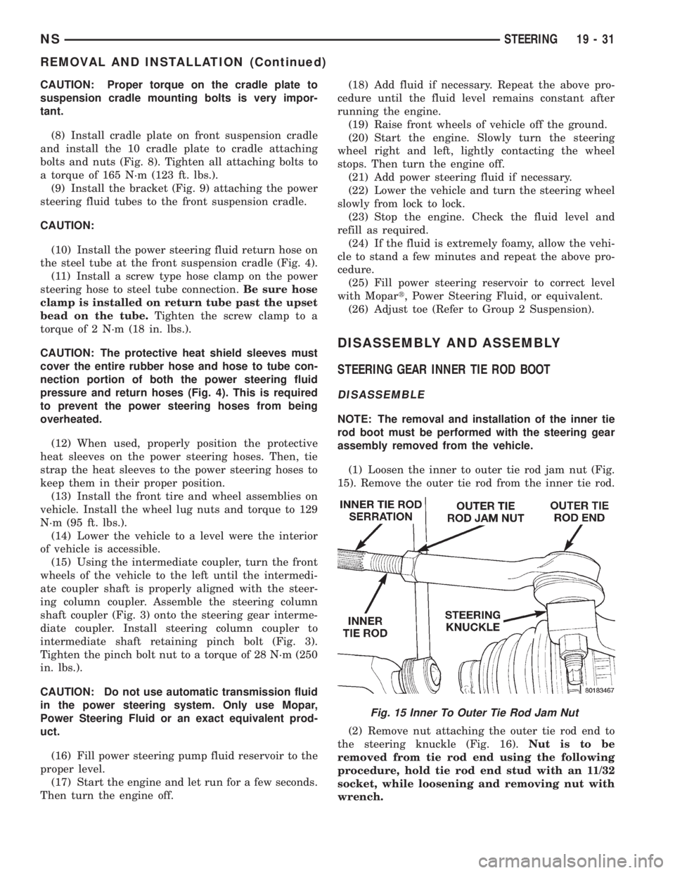
(1) Loosen the inner to outer tie rod jam nut (Fig.
15). Remove the outer tie rod from the inner tie rod.
(2) Remove nut attaching the outer tie rod end to
the steering knuckle (Fig. 16).Nut is to be
removed from tie rod end using the following
procedure, hold tie rod end stud with an 11/32
socket, while loosening and removing nut with
wrench.
Fig. 15 Inner To Outer Tie Rod Jam Nut
NSSTEERING 19 - 31
REMOVAL AND INSTALLATION (Continued)
Page 1474 of 1938
(4) Raise the front wheels off the ground.
(5) Slowly turn the steering wheel right and left,
lightly contacting the wheel stops at least 20 times.
(6) Check the fluid level add if necessary.
(7) Lower the vehicle, start the engine and turn
the steering wheel slowly from lock to lock.
(8) Stop the engine and check the fluid level and
refill as required.
(9) If the fluid is extremely foamy or milky look-
ing, allow the vehicle to stand a few minutes and
repeat the procedure.
CAUTION: Do not run a vehicle with foamy fluid for
an extended period. This may cause pump damage.
REMOVAL AND INSTALLATION
POWER STEERING PUMPÐ2.5L DIESEL
NOTE: The power steering pump is mounted below
the fuel pump on the left side of the engine. The
vehicle should be raised on a hoist to access the
pump from below.
REMOVAL
(1) Remove serpentine drive belt. Refer to Group 7,
Cooling System, for procedure.
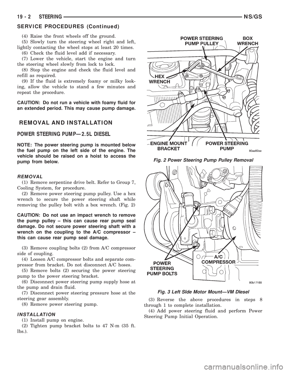
(2) Remove power steering pump pulley. Use a hex
wrench to secure the power steering shaft while
removing the pulley bolt with a box wrench. (Fig. 2)
CAUTION: Do not use an impact wrench to remove
the pump pulley ± this can cause rear pump seal
damage. Do not secure power steering shaft with a
wrench on the coupling to the A/C compressor ±
this can cause rear pump seal damage.
(3) Remove coupling bolts (2) from A/C compressor
side of coupling.
(4) Loosen A/C compressor bolts and separate com-
pressor from bracket. Do not disconnect A/C hoses.
(5) Remove bolts (2) securing the power steering
pump to the power steering bracket.
(6) Disconnect power steering pump supply hose at
the pump and drain fluid.
(7) Disconnect power steering pressure hose at the
steering gear assembly.
(8) Remove power steering pump.
INSTALLATION
(1) Install pump on engine.
(2) Tighten pump bracket bolts to 47 N´m (35 ft.
lbs.).(3) Reverse the above procedures in steps 8
through 1 to complete installation.
(4) Add power steering fluid and perform Power
Steering Pump Initial Operation.
Fig. 2 Power Steering Pump Pulley Removal
Fig. 3 Left SIde Motor MountÐVM DIesel
19 - 2 STEERINGNS/GS
SERVICE PROCEDURES (Continued)
Page 1492 of 1938
(13) Remove the pan and clean all sealant from
the pan and transaxle mating surfaces. Clean the
magnet and the inside of the pan.
(14) Separate the filter from the valve body to
allow additional fluid to drain from the transaxle.
Inspect the filter O-ring for any damage and replace
as necessary.
(15) After the transaxle has stopped draining,
reinstall the filter and O-ring.
(16) Apply a 1/8 inch bead of Mopar RTV Sealant
to the mounting flange of the transaxle oil pan.
Apply RTV Sealant to the underside of the attaching
bolts. Attach the oil pan to the transaxle. Tighten the
bolts to 19 N²m (165 in. lbs.).
(17) Lower the vehicle and add 4 Quarts of Mopar
ATF Plus 3 Type 7176 transaxle fluid.
(18) Start the engine and allow it to idle for a min-
imum of one minute. With the parking brake applied,
press your foot on the service brake and cycle the
transaxle from park to all gear positions ending in
neutral or park.
(19) Check the transaxle fluid level and add an
appropriate amount to bring the transaxle fluid level
to 3mm (1/8 in.) below the ADD mark on the dip-
stick.
(20) Recheck the fluid level after the transaxle is
at normal operating temperature. The level should be
in the HOT range.
FLUID DRAIN AND REFILL
(1) Raise vehicle on a hoist (See Group 0, Lubrica-
tion). Place a drain container with a large opening,
under transaxle oil pan.
(2) Loosen pan bolts and tap the pan at one corner
to break it loose allowing fluid to drain, then remove
the oil pan.
(3) Install a new filter and gasket on bottom of the
valve body and tighten retaining screws to 5 N´m (40
inch-pounds).
(4) Clean the oil pan and magnet. Reinstall pan
using new sealant. Tighten oil pan bolts to 19 N´m
(165 in. lbs.).
(5) Pour four quarts of Mopar ATF PLUS 3 (Auto-
matic Transmission Fluid) Type 7176 through the
dipstick opening.
(6) Start engine and allow to idle for at least one
minute. Then, with parking and service brakes
applied, move selector lever momentarily to each
position, ending in the park or neutral position.
(7) Add sufficient fluid to bring level to 1/8 inch
below the ADD mark.
(8) Recheck fluid level after transaxle is at normal
operating temperature. The level should be in the
HOT region.
ALUMINUM THREAD REPAIR
Damaged or worn threads in the aluminum transaxle
case and valve body can be repaired by the use of Heli-
Coils, or equivalent. This repair consists of drilling out
the worn-out damaged threads. Then tapping the hole
with a Heli-Coil tap, or equivalent, and installing a
Heli-Coil insert, or equivalent, into the hole. This
brings the hole back to its original thread size.
Heli-Coil, or equivalent, tools and inserts are readily
available from most automotive parts suppliers.
FLUSHING COOLERS AND TUBES
When a transaxle failure has contaminated the
fluid, the oil cooler(s) must be flushed. The cooler
bypass valve in the transaxle must be replaced also.
The torque converter must also be replaced with an
exchange unit. This will ensure that metal particles
or sludged oil are not later transferred back into the
reconditioned (or replaced) transaxle.
The recommended procedure for flushing the cool-
ers and tubes is to use Tool 6906A Cooler Flusher.
WARNING: WEAR PROTECTIVE EYEWEAR THAT
MEETS THE REQUIREMENTS OF OSHA AND ANSI
Z87.1±1968. WEAR STANDARD INDUSTRIAL RUB-
BER GLOVES.
KEEP LIGHTED CIGARETTES, SPARKS, FLAMES,
AND OTHER IGNITION SOURCES AWAY FROM THE
AREA TO PREVENT THE IGNITION OF COMBUSTI-
BLE LIQUIDS AND GASES. KEEP A CLASS (B) FIRE
EXTINGUISHER IN THE AREA WHERE THE
FLUSHER WILL BE USED.
KEEP THE AREA WELL VENTILATED.
DO NOT LET FLUSHING SOLVENT COME IN CON-
TACT WITH YOUR EYES OR SKIN: IF EYE CONTAM-
INATION OCCURS, FLUSH EYES WITH WATER FOR
15 TO 20 SECONDS. REMOVE CONTAMINATED
CLOTHING AND WASH AFFECTED SKIN WITH
SOAP AND WATER. SEEK MEDICAL ATTENTION.
COOLER FLUSH USING TOOL 6906A
(1) Remove cover plate filler plug on Tool 6906A.
Fill reservoir 1/2 to 3/4 full of fresh flushing solution.
Flushing solvents are petroleum based solutions gen-
erally used to clean automatic transmission compo-
nents.DO NOTuse solvents containing acids, water,
gasoline, or any other corrosive liquids.
(2) Reinstall filler plug on Tool 6906A.
(3) Verify pump power switch is turned OFF. Con-
nect red alligator clip to positive (+) battery post.
Connect black (-) alligator clip to a good ground.
(4) Disconnect the cooler lines at the transmission.
NOTE: When flushing transmission cooler and
lines, ALWAYS reverse flush.
21 - 18 TRANSAXLE AND POWER TRANSFER UNITNS
SERVICE PROCEDURES (Continued)
Page 1525 of 1938
Inspect all valve springs for distortion and col-
lapsed coils. Inspect all valves and plugs for burrs,
nicks, and scores. Small nicks and scores may be
removed with crocus cloth, providing extreme care is
taken not to round off sharp edges. The sharpness of
these edges is vitally important. It prevents foreign
matter from lodging between valve and valve body.
This reduces the possibility of sticking. Inspect all
valves and plugs for freedom of operation in valve
body bores.
When bores, valves, and plugs are clean and dry,
the valves and plugs should fall freely in the bores.
The valve body bores do not change its dimensions
with use. Therefore, a valve body that was function-
ing properly when vehicle was new, will operate cor-
rectly if it is properly and thoroughly cleaned. There
is no need to replace valve body unless it is damaged
in handling.
ADJUSTMENTS
GEARSHIFT CABLE ADJUSTMENT
Lift and rotate the gearshift hand lever into the
park (P) gate position and remove the ignition key.
This confirms the shift lever is in the gated park (P)
position.
After confirming the park gate position, turn the
ignition switch. If the starter will operate, the park
gate position is correct. Move the shift lever into the
neutral (N) position. If the starter will operate in this
position, the linkage is properly adjusted. If the
starter fails to operate in either position, linkage
adjustment is required.
(1) Park the vehicle on level ground and set the
parking brake.
(2) Place the gearshift lever in park (P) gate posi-
tion and remove key.
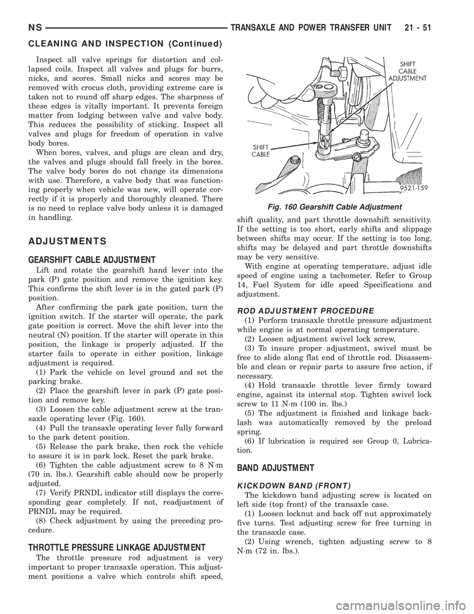
(3) Loosen the cable adjustment screw at the tran-
saxle operating lever (Fig. 160).
(4) Pull the transaxle operating lever fully forward
to the park detent position.
(5) Release the park brake, then rock the vehicle
to assure it is in park lock. Reset the park brake.
(6) Tighten the cable adjustment screw to 8 N´m
(70 in. lbs.). Gearshift cable should now be properly
adjusted.
(7) Verify PRNDL indicator still displays the corre-
sponding gear completely. If not, readjustment of
PRNDL may be required.
(8) Check adjustment by using the preceding pro-
cedure.
THROTTLE PRESSURE LINKAGE ADJUSTMENT
The throttle pressure rod adjustment is very
important to proper transaxle operation. This adjust-
ment positions a valve which controls shift speed,shift quality, and part throttle downshift sensitivity.
If the setting is too short, early shifts and slippage
between shifts may occur. If the setting is too long,
shifts may be delayed and part throttle downshifts
may be very sensitive.
With engine at operating temperature, adjust idle
speed of engine using a tachometer. Refer to Group
14, Fuel System for idle speed Specifications and
adjustment.
ROD ADJUSTMENT PROCEDURE
(1) Perform transaxle throttle pressure adjustment
while engine is at normal operating temperature.
(2) Loosen adjustment swivel lock screw.
(3) To insure proper adjustment, swivel must be
free to slide along flat end of throttle rod. Disassem-
ble and clean or repair parts to assure free action, if
necessary.
(4) Hold transaxle throttle lever firmly toward
engine, against its internal stop. Tighten swivel lock
screw to 11 N´m (100 in. lbs.)
(5) The adjustment is finished and linkage back-
lash was automatically removed by the preload
spring.
(6) I
f lubrication is required see Group 0, Lubrica-
tion.
BAND ADJUSTMENT
KICKDOWN BAND (FRONT)
The kickdown band adjusting screw is located on
left side (top front) of the transaxle case.
(1) Loosen locknut and back off nut approximately
five turns. Test adjusting screw for free turning in
the transaxle case.
(2) Using wrench, tighten adjusting screw to 8
N´m (72 in. lbs.).
Fig. 160 Gearshift Cable Adjustment
NSTRANSAXLE AND POWER TRANSFER UNIT 21 - 51
CLEANING AND INSPECTION (Continued)
Page 1548 of 1938
TORQUE MANAGEMENT
Most 41TE transaxles utilize torque management.
Torque management is a unique function of the Pow-
ertrain Control Module (PCM). The PCM receives
output signals from the Transmission Control Module
(TCM) and many various engine sensors. The PCM
evaluates these signals and decides if it is necessary
to decrease the output of the engine's torque. This
reduction in torque does not interfere with the nor-
mal operation of the vehicle. This reduction in torque
will prolong the life of the drivetrain components.
Torque reduction is not noticeable in normal driving
functions. The torque reduction function shuts off
above 16 MPH.
ON-BOARD DIAGNOSTICS
This vehicle utilizes a diagnostic system called
OBDII. The powertrain control module communicates
with the Transmission Control Module. Whenever
the transaxle sets a fault in the Transmission Con-
trol Module (dependent on which fault is set), the
powertrain control module will turn on a MIL (Mal-
function Indicator Lamp) on the instrument cluster.
By reading the code in the powertrain control module
it will tell you where the fault occurred. If the fault
occurred in the transaxle, the controller will read a
CODE 45.For further information regarding OBDII,
refer to Group 25, Emission Systems.
These controls provide comprehensive, on-board
transaxle diagnostics. The information available can
aid in transaxle diagnosis. For example, apply ele-
ment buildup rate indicates solenoid performance.
Also included are self diagnostic functions. Self diag-
nostics allow the technician to test the condition of
the electronic controls. The Transmission Control
Module continuously monitors its critical functions. It
also records any malfunctions, and the number of
engine starts since the last malfunction. This allows
the technician to use the information in the event of
a customer complaint.
TRANSMISSION CONTROL MODULE
Do not interchange Transmission Control Modules
with previous year transmission control modules. If a
same year TCM is being used from a different vehi-
cle, the following procedures must be performed:
²Quick Learn Procedure
²Electronic Pinion Factor Procedure
The Transmission Control Module is located on the
right inner fender panel, in the engine compartment.
It is held in place by four mounting screws.NOTE: If the Transmission Control Module has
been replaced, the following procedures must be
performed:
²Quick Learn Procedure: This procedure will
allow the transmission control module to learn the
characteristics of the vehicle.
²Electronic Pinion Factor Procedure: This proce-
dure will reprogram the TCM to compensate for dif-
ferent tire sizes and final drive ratios.
GEARSHIFT AND PARKING LOCK CONTROLS
The transaxle is controlled by a lever type gear-
shift incorporated within the steering column. The
control has six selector lever positions: P (park), R
(reverse), N (neutral), and D (drive), 2 (second), and
1 (first). The parking lock is applied by moving the
selector lever past a gate to the P position.Do not
apply the parking lock until the vehicle has
stopped; otherwise, a severe ratchet noise will
occur.
TRANSMISSION RANGE SENSOR
The 41TE transaxle is equipped with a transmis-
sion range sensor that is located on top of the valve
body. This sensor will allow for accurate transmission
gear position measurement.
To service the transmission range sensor (TRS),
you must remove the valve body. For repair proce-
dures, refer to the Removal and Installation section
within this group.
Also located within the TRS is a transmission tem-
perature sensor. This sensor is used to measure the
transmission fluid sump temperature. The transmis-
sion temperature sensor is serviced with the TRS as
a unit.
SHIFT POSITION INDICATOR
The shifter position indicator is located in the
instrument cluster. The shifter position indicator out-
lines with a box the gear position the transaxle man-
ual valve lever is in.
The transmission range sensor (located on the
valvebody) sends a signal to the TCM on the position
of the transaxle manual valve lever. The TCM
receives the switch signal and processes the data.
The TCM sends the Shift Lever Position (SLP) infor-
mation to the BCM via the CCD bus. The BCM then
outlines with a box the appropriate shifter position
indicator in the instrument cluster.
To replace the shifter position indicator, refer to
Group 8E, Instrument Panel And Gauges.
21 - 74 TRANSAXLE AND POWER TRANSFER UNITNS
DESCRIPTION AND OPERATION (Continued)
Page 1555 of 1938
(11) Recheck the fluid level after the transaxle is
at normal operating temperature. The level should be
in the HOT range. Drive the vehicle a minimum of
10 miles.
(12) Raise the vehicle on the hoist.
(13) Remove the pan and clean all sealant from
the pan and transaxle mating surfaces. Clean the
magnet and the inside of the pan.
(14) Separate the filter from the valve body to
allow additional fluid to drain from the transaxle.
Inspect the filter O-ring for any damage and replace
as necessary.
(15) After the transaxle has stopped draining,
reinstall the filter and O-ring.
(16) Apply a 1/8 inch bead of Mopar RTV Sealant
to the mounting flange of the transaxle oil pan.
Apply RTV Sealant to the underside of the attaching
bolts. Attach the oil pan to the transaxle. Tighten the
bolts to 19 N´m (165 in. lbs.).
(17) Lower the vehicle and add 4 Quarts of Mopar
ATF Plus 3 Type 7176 transaxle fluid.
(18) Start the engine and allow it to idle for a min-
imum of one minute. With the parking brake applied,
press your foot on the service brake and cycle the
transaxle from park to all gear positions ending in
neutral or park.
(19) Check the transaxle fluid level and add an
appropriate amount to bring the transaxle fluid level
to 3mm (1/8 in.) below the ADD mark on the dip-
stick.
(20) Recheck the fluid level after the transaxle is
at normal operating temperature. The level should be
in the HOT range.
FLUID DRAIN AND REFILL
(1) Raise vehicle on a hoist (See Group 0, Lubrica-
tion). Place a drain container with a large opening,
under transaxle oil pan.
(2) Loosen pan bolts and tap the pan at one corner
to break it loose allowing fluid to drain, then remove
the oil pan.
(3) Install a new filter and O-ring on bottom of the
valve body.
(4) Clean the oil pan and magnet. Reinstall pan
using new MOPARtRTV sealant. Tighten oil pan
bolts to 19 N´m (165 in. lbs.).
(5) Pour four quarts of MOPARtATF PLUS 3
(Automatic Transmission Fluid) Type 7176 through
the fill tube.
(6) Start engine and allow to idle for at least one
minute. Then, with parking and service brakes
applied, move selector lever momentarily to each
position, ending in the park or neutral position.(7) Add sufficient fluid to bring level to 1/8 inch
below the ADD mark.
CAUTION: Do not overfill transaxle. Do not add oil
if level is between: Lower holes for warm oil
(100ÉF). Upper holes for hot oil (180ÉF).
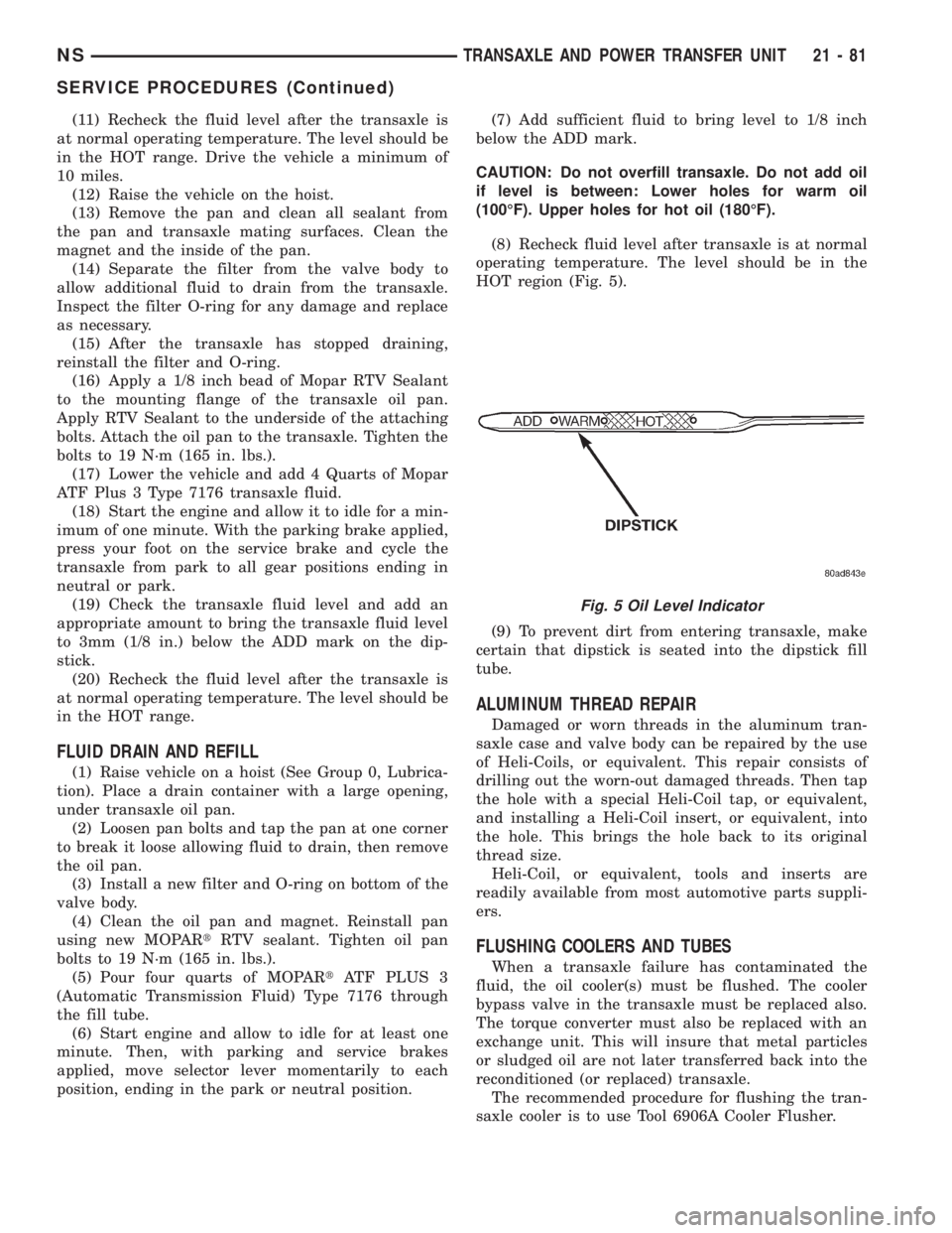
(8) Recheck fluid level after transaxle is at normal
operating temperature. The level should be in the
HOT region (Fig. 5).
(9) To prevent dirt from entering transaxle, make
certain that dipstick is seated into the dipstick fill
tube.
ALUMINUM THREAD REPAIR
Damaged or worn threads in the aluminum tran-
saxle case and valve body can be repaired by the use
of Heli-Coils, or equivalent. This repair consists of
drilling out the worn-out damaged threads. Then tap
the hole with a special Heli-Coil tap, or equivalent,
and installing a Heli-Coil insert, or equivalent, into
the hole. This brings the hole back to its original
thread size.
Heli-Coil, or equivalent, tools and inserts are
readily available from most automotive parts suppli-
ers.
FLUSHING COOLERS AND TUBES
When a transaxle failure has contaminated the
fluid, the oil cooler(s) must be flushed. The cooler
bypass valve in the transaxle must be replaced also.
The torque converter must also be replaced with an
exchange unit. This will insure that metal particles
or sludged oil are not later transferred back into the
reconditioned (or replaced) transaxle.
The recommended procedure for flushing the tran-
saxle cooler is to use Tool 6906A Cooler Flusher.
Fig. 5 Oil Level Indicator
NSTRANSAXLE AND POWER TRANSFER UNIT 21 - 81
SERVICE PROCEDURES (Continued)
Page 1754 of 1938
Some water leaks must be tested for a considerable
length of time to become apparent. When a leak
appears, find the highest point of the water track or
drop. The highest point usually will show the point of
entry. After leak point has been found, repair the
leak and water test to verify that the leak has
stopped.
Locating the entry point of water that is leaking
into a cavity between panels can be difficult. The
trapped water may splash or run from the cavity,
often at a distance from the entry point. Most water
leaks of this type become apparent after accelerating,
stopping, turning, or when on an incline.
MIRROR INSPECTION METHOD
When a leak point area is visually obstructed, use
a suitable mirror to gain visual access. A mirror can
also be used to deflect light to a limited-access area
to assist in locating a leak point.
BRIGHT LIGHT LEAK TEST METHOD
Some water leaks in the luggage compartment can
be detected without water testing. Position the vehi-
cle in a brightly lit area. From inside the darkened
luggage compartment inspect around seals and body
seams. If necessary, have a helper direct a drop light
over the suspected leak areas around the luggage
compartment. If light is visible through a normally
sealed location, water could enter through the open-
ing.
PRESSURIZED LEAK TEST METHOD
When a water leak into the passenger compart-
ment cannot be detected by water testing, pressurize
the passenger compartment and soap test exterior of
the vehicle. To pressurize the passenger compart-
ment, close all doors and windows, start engine, and
set heater control to high blower in HEAT position. If
engine can not be started, connect a charger to the
battery to ensure adequate voltage to the blower.
With interior pressurized, apply dish detergent solu-
tion to suspected leak area on the exterior of the
vehicle. Apply detergent solution with spray device or
soft bristle brush. If soap bubbles occur at a body
seam, joint, seal or gasket, the leak entry point could
be at that location.
WIND NOISE
Wind noise is the result of most air leaks. Air leaks
can be caused by poor sealing, improper body compo-
nent alignment, body seam porosity, or missing plugs
in the engine compartment or door hinge pillar areas.
All body sealing points should be airtight in normal
driving conditions. Moving sealing surfaces will not
always seal airtight under all conditions. At times,
side glass or door seals will allow wind noise to be
noticed in the passenger compartment during highcrosswinds. Over compensating on door or glass
adjustments to stop wind noise that occurs under
severe conditions can cause premature seal wear and
excessive closing or latching effort. After a repair pro-
cedure has been performed, test vehicle to verify
noise has stopped before returning vehicle to use.
Wind noise can also be caused by improperly fitted
exterior moldings or body ornamentation. Loose
moldings can flutter, creating a buzzing or chattering
noise. An open cavity or protruding edge can create a
whistling or howling noise. Inspect the exterior of the
vehicle to verify that these conditions do not exist.
VISUAL INSPECTION BEFORE TESTS
Verify that floor and body plugs are in place and
body components are aligned and sealed. If component
alignment or sealing is necessary, refer to the appro-
priate section of this group for proper procedures.
ROAD TESTING WIND NOISE
(1) Drive the vehicle to verify the general location
of the wind noise.
(2) Apply 50 mm (2 in.) masking tape in 150 mm
(6 in.) lengths along weatherstrips, weld seams or
moldings. After each length is applied, drive the vehi-
cle. If noise goes away after a piece of tape is applied,
remove tape, locate, and repair defect.
POSSIBLE CAUSE OF WIND NOISE
²Moldings standing away from body surface can
catch wind and whistle.
²Gaps in sealed areas behind overhanging body
flanges can cause wind-rushing sounds.
²Misaligned movable components.
²Missing or improperly installed plugs in pillars.
²Weld burn through holes.
SERVICE PROCEDURES
HEAT STAKING
(1) Remove trim panel.
(2) Bend or move the trim panel components at
the heat staked joints. Observe the heat staked loca-
tions and/or component seams for looseness.
(3) Heat stake the components.
(a) If the heat staked or component seam loca-
tion is loose, hold the two components tightly
together and using a soldering gun with a flat tip,
melt the material securing the components
together. Do not over heat the affected area, dam-
age to the exterior of the trim panel may occur.
(b) If the heat staked material is broken or miss-
ing, use a hot glue gun to apply new material to
the area to be repaired. The panels that are being
heat staked must be held together while the apply-
ing the glue. Once the new material is in place, it
23 - 24 BODYNS
DIAGNOSIS AND TESTING (Continued)
Page 1824 of 1938
COOLDOWN TEST ENTRY
TO INITIATE TESTS:
²Set Blower motor ON HIGH
²Set Mode position to Panel
²Open all A/C outlets
²Set Temperature to Cold (Both slide pots if
equipped)
²Depress WASH and A/C simultaneously for 5
Seconds
NOTE: Prior to start of test, If the evaporator is
already cold, the system will fail test. To correct,
operate system with A/C OFF and the blower motor
ON high for three minutes prior to starting test.
RESULTS:
²All LED's will turn on for 5 Seconds
²Cooldown Test is running when A/C and
RECIRC. are alternately flashing. If A/C and
RECIRC. are flashing simultaneously, Cooldown has
failed.
CALIBRATION DIAGNOSTICS AND
COOLDOWN ABORT
Test can be aborted by doing one of the following:
²Depressing Rear Window Defogger, RECIRC and
Rear Wiper buttons.
²Cycling Ignition OFF and then ON.
²Control will automatically abort after 15 min-
utes from the time Calibration Diagnostics and
Cooldown was entered.
The HVAC control module will return to normal
operation or may indicate unsuccessful Calibration
Diagnostics or Cooldown test by LED's flashing
simultaneously.
EEPROM DATA
Calibration Diagnostics, Cooldown Status and
evaporator temperature Fin Sensor values are stored
in an EEPROM memory internal to the control. The
microcomputer within the HVAC control module uses
this information:
²To determine if Cooldown needs to run
²For proper position of the Heater-A/C unit
assembly doors
ACTUATOR CALIBRATION AND
DIAGNOSTICS.
NOTE: Do not run actuators unless they are prop-
erly mounted on the HVAC control module.
Actuator end point calibration takes approximately
60 seconds. The REAR WIPER and INTERMITTENT
LED's will flash alternately during the test. The con-
trol will cycle the Blend actuator(s) to the Heat stopfirst then back to Cold. After the Blend actuator(s)
have been calibrated the Mode actuator will be cycled
to Defrost and then to Panel. Successful calibration
is defined as actuator travel falling within their min-
imum and maximum limits.
BLEND/PASSENGER ACTUATOR BACKGROUND
The Blend/Passenger Actuator can move the tem-
perature door in two directions. When the voltage at
Pin 12 of the control module is high, about 11.5 volts,
and the voltage at Pin 17 is low, about 1.5 volts, the
door will move towards the Heat position. When Pin
17 is High and Pin 12 is Low the door will move
towards the Cold position. When both Pins are high
or both Pins are low, the actuator will not move. The
Blend/Passenger feedback signal is a voltage signal
that is supplied by the actuator to the control. The
signal will be about 4.0 volts in the Heat position
and 1.0 volt in the Cold position. As the position of
the Blend/Passenger actuator changes, so will the
feedback signal. The feedback signal is necessary for
the correct positioning of the temperature door.
DRIVER ACTUATOR BACKGROUND
The Driver Actuator can move the temperature
door in two directions. When the voltage at Pin 15 of
the control module is high, about 11.5 volts, and the
voltage at Pin 13 is low, about 1.5 volts the door will
move towards the Cold position. When Pin 13 is High
and Pin 15 is Low the door will move towards the
Heat position. When both Pins are high or when both
Pins are low, the actuator will not move. The Driver
feedback signal is a voltage signal that is supplied by
the actuator to the control. The signal will be about
4.0 volts in the Heat position and 1.0 volt in the Cold
position. As the position of the Driver Actuator
changes, so will the feedback signal. The feedback
signal is necessary for the correct positioning of the
temperature door.
MODE ACTUATOR BACKGROUND
The Mode actuator can move the mode door in two
directions. When the voltage at Pin 18 of the control
module is high, about 11.5 volts, and the voltage at
Pin 12 is low, about 1.5 volts the door will move
towards the Panel position. When Pin 12 is High and
Pin 18 is Low the door will move towards the Defrost
position. When both Pin are high or when both Pins
are low, the actuator will not move. The Mode door
feedback signal is a voltage signal that is supplied by
the actuator to the control. The signal will be about
4.5 volts in the Panel position and 0.5 volts in the
Defrost position. As the position of the Mode actuator
changes, so will the feedback signal. The feedback
signal is necessary for the correct positioning of the
mode door.
24 - 8 HEATING AND AIR CONDITIONINGNS
DIAGNOSIS AND TESTING (Continued)
Page 1827 of 1938
After calibration, Rear Wiper LED flashing
once, Intermittent LED flashing six times. The
evaporator probe is shorted.
(1) Using a voltmeter, check Pin 1 of the evapora-
tor probe wiring connector for 0.1 - 4.75 volts. If OK,
go to Step 2. If less than 0.1 volts, check for loose or
corroded connector, open or shorted circuit and repair
as necessary.
(2) Using a ohmmeter, check Pin 2 for a good
ground, If OK, go to Step 3. If not OK, check for
shorted circuit and repair as necessary.
(3) If ground and power circuit are OK, replace
Evaporator Probe
(4) Once repairs are completed, press the intermit-
tent button about 5 seconds until all LED's light to
remove fault code from memory. Then repeat the Cal-
ibration Diagnostic and Cooldown test. Repeating the
test is necessary to clear the fault codes.
After calibration, Rear Wiper LED flashing
once, Intermittent LED flashing seven times.
The Driver's temperature actuator on a zone
system did not reach cold stop.
(1) Check if the correct HVAC control module was
used.
(2) Using a voltmeter, check at the temperature
door actuator wiring connector, check Pin 1 for bat-
tery voltage. Move the HVAC control from cold to the
hot position, check Pin 4 voltage it should change
from 0.5 - 1.5 volts 3.5 - 4.5 volts. If voltage is OK, go
to Step 3. If not OK, check for loose or corroded con-
nector, open or shorted circuit and repair as neces-
sary.
(3) Remove actuator, and check if the gear pins are
in the correct track on cam or if they are binding. If
OK, go to Step 4. If not OK, repair as necessary.
(4) Check for binding doors, if door are binding
repair as necessary. If gears and door are OK, replace
actuator.
(5) Once repairs are completed repeat the Calibra-
tion Diagnostic and Cooldown test. Repeating the
test is necessary to clear the fault codes.
After calibration, Rear Wiper LED flashing
once, Intermittent LED flashing eight times.
The Driver's temperature actuator on a zone
system did not reach hot stop.
(1) Check if the correct HVAC control module was
used.
(2) Using a voltmeter, check at the temperature
door actuator wiring connector, check Pin 1 for bat-
tery voltage. Move the HVAC control from hot to cold
position, Pin 4 voltage it should change from 3.5 - 4.5
volts to 0.5 - 1.5 volts. If voltage is OK, go to Step 3.
If not OK, check for loose or corroded connector, open
or shorted circuit and repair as necessary.(3) Remove actuator, and check if the gear pins are
in the correct track on cam or if they are binding. If
OK, go to Step 4. If not OK, repair as necessary.
(4) Check for binding door, if door is binding repair
as necessary. If gears and door are OK, replace
actuator.
(5) Once repairs are completed repeat the Calibra-
tion Diagnostic and Cooldown test. Repeating the
test is necessary to clear the fault codes.
After calibration, Rear Wiper LED flashing
once, Intermittent LED flashing nine times.
The HVAC control module, has a internal
failure.
(1) Replace the HVAC control module.
(2) Once repairs are completed repeat the Calibra-
tion Diagnostic and Cooldown test. Repeating the
test is necessary to clear the fault codes.
After calibration and testing the A/C and
RECIRC LED flashing simultaneously. Failed
Cooldown test.
(1) Determine if the refrigerant system is operat-
ing correctly:
²Check the outlet air temperature
²Feel the compressor suction plumbing, is it hot?
(2) If not OK, go to Step 3. If OK, repeat the Cal-
ibration Diagnostic and Cooldown test.
(3) If system does not seem to be operating cor-
rectly, perform diagnostics for poor performance:
²Low refrigerant charge
²No charge
²Compressor not operating
Verify that the test was done with the evaporator
at room temperature. The test consists of starting
the compressor and measuring the time it takes for
the evaporator temperature to fall 7ÉC (20ÉF). If the
compressor has been running, the evaporator is cold
already and will not be capable of falling 7ÉC (20ÉF).
If the test was run with a cold evaporator, turn A/C
off and turn the blower motor switch to high position
for 3 to 5 minutes till the evaporator is to room tem-
perature. Then repeat the Calibration Diagnostic and
Cooldown test.
If refrigerant system is performing properly and
the system will not pass test. Repeat the Calibration
Diagnostic and Cooldown test to determine if the
evaporator temperature FIN sensor has developed an
open or a short circuit. If the HVAC control module
still passes Calibration test, verify Cooldown test
manually with a pocket thermometer. The outlet air
temperature must drop at least 7ÉC (20ÉF) within
two minutes. If the vehicle passes with the manual
thermometer, take HVAC control to level 4 (evapora-
tor probe temperature readout) and repeat the
Cooldown test. Ensure the evaporator is at room tem-
perature before starting test. Check if evaporator
NSHEATING AND AIR CONDITIONING 24 - 11
DIAGNOSIS AND TESTING (Continued)