sensor CHRYSLER VOYAGER 1996 Service Manual
[x] Cancel search | Manufacturer: CHRYSLER, Model Year: 1996, Model line: VOYAGER, Model: CHRYSLER VOYAGER 1996Pages: 1938, PDF Size: 55.84 MB
Page 1271 of 1938
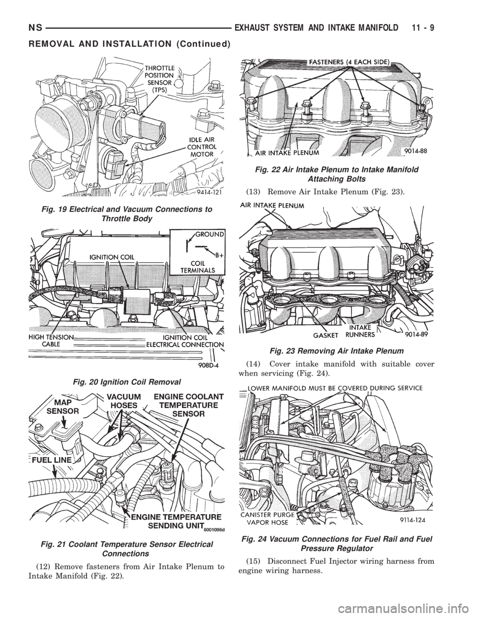
(12) Remove fasteners from Air Intake Plenum to
Intake Manifold (Fig. 22).(13) Remove Air Intake Plenum (Fig. 23).
(14) Cover intake manifold with suitable cover
when servicing (Fig. 24).
(15) Disconnect Fuel Injector wiring harness from
engine wiring harness.
Fig. 19 Electrical and Vacuum Connections to
Throttle Body
Fig. 20 Ignition Coil Removal
Fig. 21 Coolant Temperature Sensor Electrical
Connections
Fig. 22 Air Intake Plenum to Intake Manifold
Attaching Bolts
Fig. 23 Removing Air Intake Plenum
Fig. 24 Vacuum Connections for Fuel Rail and Fuel
Pressure Regulator
NSEXHAUST SYSTEM AND INTAKE MANIFOLD 11 - 9
REMOVAL AND INSTALLATION (Continued)
Page 1273 of 1938
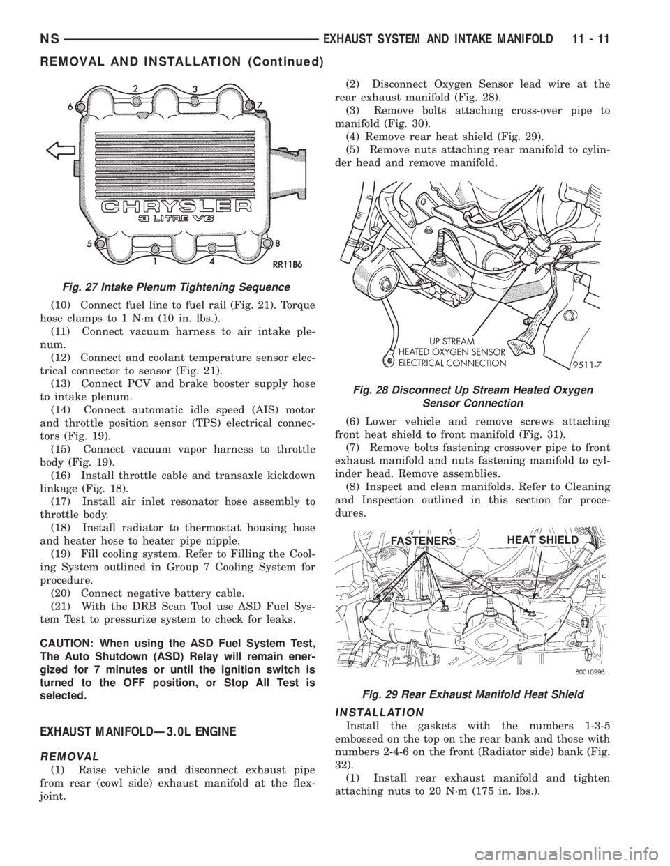
(10) Connect fuel line to fuel rail (Fig. 21). Torque
hose clamps to 1 N´m (10 in. lbs.).
(11) Connect vacuum harness to air intake ple-
num.
(12) Connect and coolant temperature sensor elec-
trical connector to sensor (Fig. 21).
(13) Connect PCV and brake booster supply hose
to intake plenum.
(14) Connect automatic idle speed (AIS) motor
and throttle position sensor (TPS) electrical connec-
tors (Fig. 19).
(15) Connect vacuum vapor harness to throttle
body (Fig. 19).
(16) Install throttle cable and transaxle kickdown
linkage (Fig. 18).
(17) Install air inlet resonator hose assembly to
throttle body.
(18) Install radiator to thermostat housing hose
and heater hose to heater pipe nipple.
(19) Fill cooling system. Refer to Filling the Cool-
ing System outlined in Group 7 Cooling System for
procedure.
(20) Connect negative battery cable.
(21) With the DRB Scan Tool use ASD Fuel Sys-
tem Test to pressurize system to check for leaks.
CAUTION: When using the ASD Fuel System Test,
The Auto Shutdown (ASD) Relay will remain ener-
gized for 7 minutes or until the ignition switch is
turned to the OFF position, or Stop All Test is
selected.
EXHAUST MANIFOLDÐ3.0L ENGINE
REMOVAL
(1) Raise vehicle and disconnect exhaust pipe
from rear (cowl side) exhaust manifold at the flex-
joint.(2) Disconnect Oxygen Sensor lead wire at the
rear exhaust manifold (Fig. 28).
(3) Remove bolts attaching cross-over pipe to
manifold (Fig. 30).
(4) Remove rear heat shield (Fig. 29).
(5) Remove nuts attaching rear manifold to cylin-
der head and remove manifold.
(6) Lower vehicle and remove screws attaching
front heat shield to front manifold (Fig. 31).
(7) Remove bolts fastening crossover pipe to front
exhaust manifold and nuts fastening manifold to cyl-
inder head. Remove assemblies.
(8) Inspect and clean manifolds. Refer to Cleaning
and Inspection outlined in this section for proce-
dures.
INSTALLATION
Install the gaskets with the numbers 1-3-5
embossed on the top on the rear bank and those with
numbers 2-4-6 on the front (Radiator side) bank (Fig.
32).
(1) Install rear exhaust manifold and tighten
attaching nuts to 20 N´m (175 in. lbs.).
Fig. 27 Intake Plenum Tightening Sequence
Fig. 28 Disconnect Up Stream Heated Oxygen
Sensor Connection
Fig. 29 Rear Exhaust Manifold Heat Shield
NSEXHAUST SYSTEM AND INTAKE MANIFOLD 11 - 11
REMOVAL AND INSTALLATION (Continued)
Page 1274 of 1938
(2) Attach exhaust pipe to exhaust manifold and
tighten bolts to 28 N´m (250 in. lbs.)
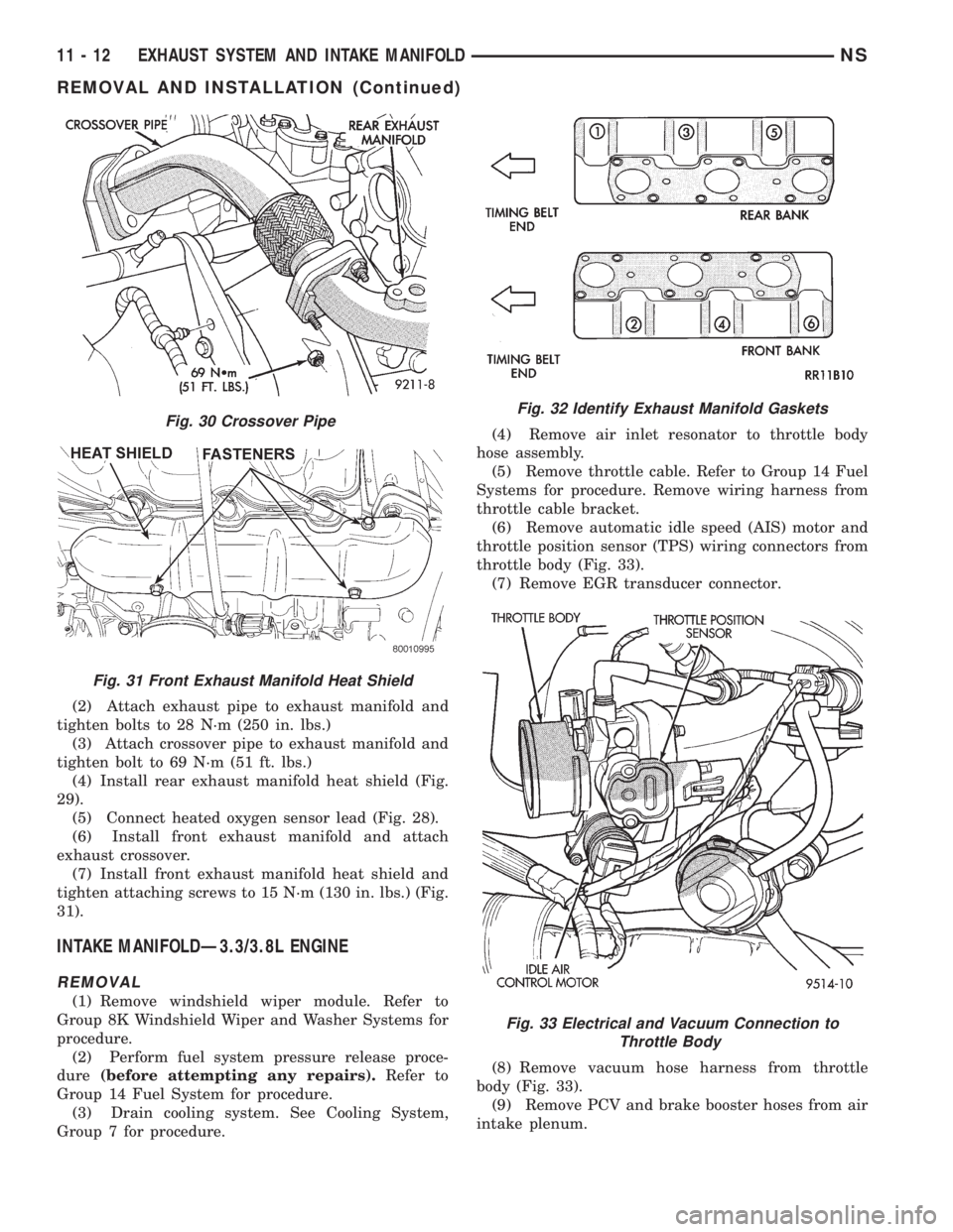
(3) Attach crossover pipe to exhaust manifold and
tighten bolt to 69 N´m (51 ft. lbs.)
(4) Install rear exhaust manifold heat shield (Fig.
29).
(5) Connect heated oxygen sensor lead (Fig. 28).
(6) Install front exhaust manifold and attach
exhaust crossover.
(7) Install front exhaust manifold heat shield and
tighten attaching screws to 15 N´m (130 in. lbs.) (Fig.
31).
INTAKE MANIFOLDÐ3.3/3.8L ENGINE
REMOVAL
(1) Remove windshield wiper module. Refer to
Group 8K Windshield Wiper and Washer Systems for
procedure.
(2) Perform fuel system pressure release proce-
dure(before attempting any repairs).Refer to
Group 14 Fuel System for procedure.
(3) Drain cooling system. See Cooling System,
Group 7 for procedure.(4) Remove air inlet resonator to throttle body
hose assembly.
(5) Remove throttle cable. Refer to Group 14 Fuel
Systems for procedure. Remove wiring harness from
throttle cable bracket.
(6) Remove automatic idle speed (AIS) motor and
throttle position sensor (TPS) wiring connectors from
throttle body (Fig. 33).
(7) Remove EGR transducer connector.
(8) Remove vacuum hose harness from throttle
body (Fig. 33).
(9) Remove PCV and brake booster hoses from air
intake plenum.
Fig. 30 Crossover Pipe
Fig. 31 Front Exhaust Manifold Heat Shield
Fig. 32 Identify Exhaust Manifold Gaskets
Fig. 33 Electrical and Vacuum Connection to
Throttle Body
11 - 12 EXHAUST SYSTEM AND INTAKE MANIFOLDNS
REMOVAL AND INSTALLATION (Continued)
Page 1275 of 1938
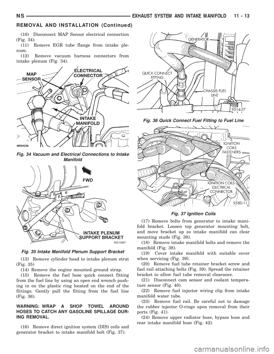
(10) Disconnect MAP Sensor electrical connection
(Fig. 34).
(11) Remove EGR tube flange from intake ple-
num.
(12) Remove vacuum harness connectors from
intake plenum (Fig. 34).
(13) Remove cylinder head to intake plenum strut
(Fig. 35)
(14) Remove the engine mounted ground strap.
(15) Remove the fuel hose quick connect fitting
from the fuel line by using an open end wrench push-
ing in on the plastic ring located on the end of the
fittings. Gently pull the fitting from the fuel line
(Fig. 36).
WARNING: WRAP A SHOP TOWEL AROUND
HOSES TO CATCH ANY GASOLINE SPILLAGE DUR-
ING REMOVAL.
(16) Remove direct ignition system (DIS) coils and
generator bracket to intake manifold bolt (Fig. 37).(17) Remove bolts from generator to intake mani-
fold bracket. Loosen top generator mounting bolt,
and move bracket up so intake manifold can clear
mounting studs (Fig. 38).
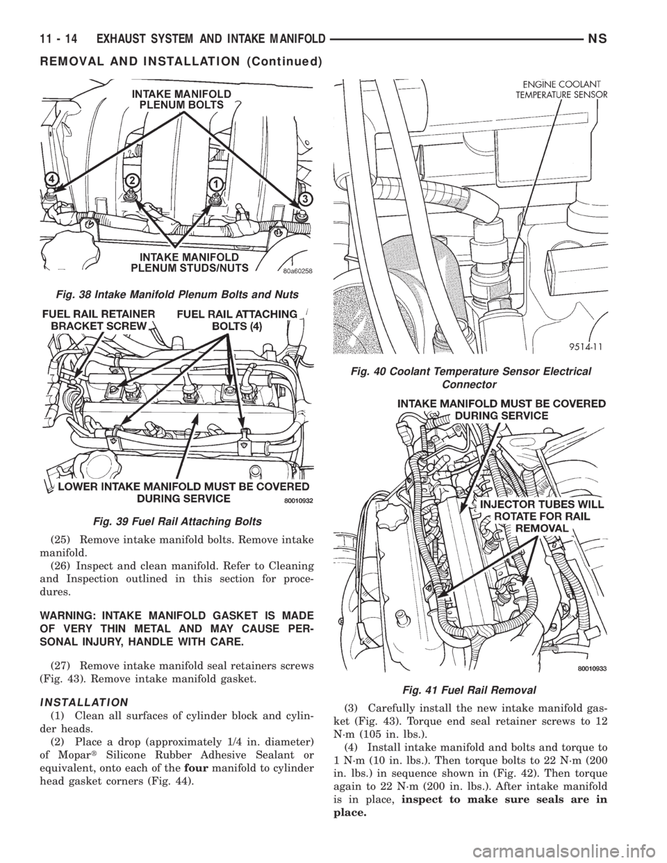
(18) Remove intake manifold bolts and remove the
manifold (Fig. 38).
(19) Cover intake manifold with suitable cover
when servicing (Fig. 39).
(20) Remove fuel tube retainer bracket screw and
fuel rail attaching bolts (Fig. 39). Spread the retainer
bracket to allow fuel tube removal clearance.
(21) Disconnect cam sensor and coolant tempera-
ture sensor (Fig. 40).
(22) Remove fuel injector wiring clip from intake
manifold water tube.
(23) Remove fuel rail. Be careful not to damage
the rubber injector O-rings upon removal from their
ports (Fig. 41).
(24) Remove upper radiator hose, bypass hose and
rear intake manifold hose (Fig. 42).
Fig. 34 Vacuum and Electrical Connections to Intake
Manifold
Fig. 35 Intake Manifold Plenum Support Bracket
Fig. 36 Quick Connect Fuel Fitting to Fuel Line
Fig. 37 Ignition Coils
NSEXHAUST SYSTEM AND INTAKE MANIFOLD 11 - 13
REMOVAL AND INSTALLATION (Continued)
Page 1276 of 1938
(25) Remove intake manifold bolts. Remove intake
manifold.
(26) Inspect and clean manifold. Refer to Cleaning
and Inspection outlined in this section for proce-
dures.
WARNING: INTAKE MANIFOLD GASKET IS MADE
OF VERY THIN METAL AND MAY CAUSE PER-
SONAL INJURY, HANDLE WITH CARE.
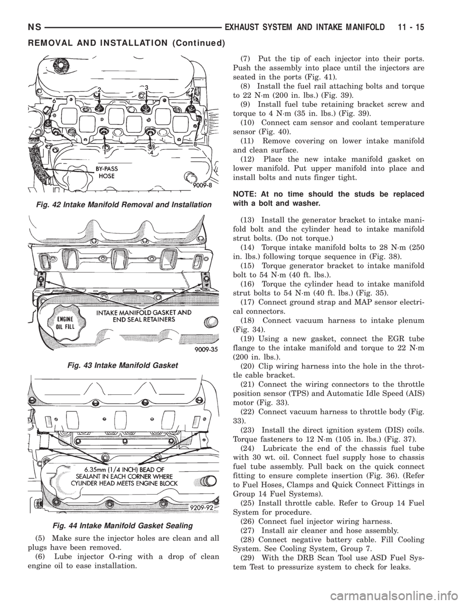
(27) Remove intake manifold seal retainers screws
(Fig. 43). Remove intake manifold gasket.
INSTALLATION
(1) Clean all surfaces of cylinder block and cylin-
der heads.
(2) Place a drop (approximately 1/4 in. diameter)
of MopartSilicone Rubber Adhesive Sealant or
equivalent, onto each of thefourmanifold to cylinder
head gasket corners (Fig. 44).(3) Carefully install the new intake manifold gas-
ket (Fig. 43). Torque end seal retainer screws to 12
N´m (105 in. lbs.).
(4) Install intake manifold and bolts and torque to
1 N´m (10 in. lbs.). Then torque bolts to 22 N´m (200
in. lbs.) in sequence shown in (Fig. 42). Then torque
again to 22 N´m (200 in. lbs.). After intake manifold
is in place,inspect to make sure seals are in
place.
Fig. 38 Intake Manifold Plenum Bolts and Nuts
Fig. 39 Fuel Rail Attaching Bolts
Fig. 40 Coolant Temperature Sensor Electrical
Connector
Fig. 41 Fuel Rail Removal
11 - 14 EXHAUST SYSTEM AND INTAKE MANIFOLDNS
REMOVAL AND INSTALLATION (Continued)
Page 1277 of 1938
(5) Make sure the injector holes are clean and all
plugs have been removed.
(6) Lube injector O-ring with a drop of clean
engine oil to ease installation.(7) Put the tip of each injector into their ports.
Push the assembly into place until the injectors are
seated in the ports (Fig. 41).
(8) Install the fuel rail attaching bolts and torque
to 22 N´m (200 in. lbs.) (Fig. 39).
(9) Install fuel tube retaining bracket screw and
torque to 4 N´m (35 in. lbs.) (Fig. 39).
(10) Connect cam sensor and coolant temperature
sensor (Fig. 40).
(11) Remove covering on lower intake manifold
and clean surface.
(12) Place the new intake manifold gasket on
lower manifold. Put upper manifold into place and
install bolts and nuts finger tight.
NOTE: At no time should the studs be replaced
with a bolt and washer.
(13) Install the generator bracket to intake mani-
fold bolt and the cylinder head to intake manifold
strut bolts. (Do not torque.)
(14) Torque intake manifold bolts to 28 N´m (250
in. lbs.) following torque sequence in (Fig. 38).
(15) Torque generator bracket to intake manifold
bolt to 54 N´m (40 ft. lbs.).
(16) Torque the cylinder head to intake manifold
strut bolts to 54 N´m (40 ft. lbs.) (Fig. 35).
(17) Connect ground strap and MAP sensor electri-
cal connectors.
(18) Connect vacuum harness to intake plenum
(Fig. 34).
(19) Using a new gasket, connect the EGR tube
flange to the intake manifold and torque to 22 N´m
(200 in. lbs.).
(20) Clip wiring harness into the hole in the throt-
tle cable bracket.
(21) Connect the wiring connectors to the throttle
position sensor (TPS) and Automatic Idle Speed (AIS)
motor (Fig. 33).
(22) Connect vacuum harness to throttle body (Fig.
33).
(23) Install the direct ignition system (DIS) coils.
Torque fasteners to 12 N´m (105 in. lbs.) (Fig. 37).
(24) Lubricate the end of the chassis fuel tube
with 30 wt. oil. Connect fuel supply hose to chassis
fuel tube assembly. Pull back on the quick connect
fitting to ensure complete insertion (Fig. 36). (Refer
to Fuel Hoses, Clamps and Quick Connect Fittings in
Group 14 Fuel Systems).
(25) Install throttle cable. Refer to Group 14 Fuel
System for procedure.
(26) Connect fuel injector wiring harness.
(27) Install air cleaner and hose assembly.
(28) Connect negative battery cable. Fill Cooling
System. See Cooling System, Group 7.
(29) With the DRB Scan Tool use ASD Fuel Sys-
tem Test to pressurize system to check for leaks.
Fig. 42 Intake Manifold Removal and Installation
Fig. 43 Intake Manifold Gasket
Fig. 44 Intake Manifold Gasket Sealing
NSEXHAUST SYSTEM AND INTAKE MANIFOLD 11 - 15
REMOVAL AND INSTALLATION (Continued)
Page 1278 of 1938
CAUTION: When using the ASD Fuel System Test,
The Auto Shutdown (ASD) Relay will remain ener-
gized for 7 minutes or until the ignition switch is
turned to the OFF position, or Stop All Test is
selected.
EXHAUST MANIFOLDSÐ3.3/3.8L ENGINE
REMOVAL
(1) Disconnect battery negative cable.
(2) Remove accessory drive belt. Refer to Accessory
Drive section located in Group 7 Cooling System for
procedure.
(3) Remove generator.
(4) Raise vehicle and disconnect exhaust pipe
from rear (cowl side) exhaust manifold at flex-joint.
(5) Disconnect down stream oxygen sensor connec-
tor.
(6) Lower exhaust system to gain access to rear
manifold.
(7) Separate EGR tube from rear manifold and
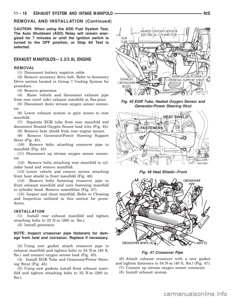
disconnect Heated Oxygen Sensor lead wire (Fig. 45).
(8) Remove heat shield from rear engine mount.
(9) Remove Generator/Power Steering Support
Strut (Fig. 45).
(10) Remove bolts attaching crossover pipe to
manifold (Fig. 45).
(11) Disconnect up stream oxygen sensor connec-
tor.
(12) Remove bolts attaching rear manifold to cyl-
inder head and remove manifold.
(13) Lower vehicle and remove screws attaching
front heat shield to front manifold (Fig. 46).
(14) Remove bolts fastening crossover pipe to
front exhaust manifold and nuts fastening manifold
to cylinder head. Remove assemblies (Fig. 47).
(15) Inspect and clean manifold. Refer to Cleaning
and Inspection outlined in this section for proce-
dures.
INSTALLATION
(1) Install rear exhaust manifold and tighten
attaching bolts to 23 N´m (200 in. lbs.).
(2) Install generator.
NOTE: Inspect crossover pipe fasteners for dam-
age from heat and corrosion. Replace if necessary.
(3) Using new gasket attach crossover pipe to
exhaust manifold and tighten bolts to 54 N´m (40 ft.
lbs.) and connect oxygen sensor lead (Fig. 45).
(4) Install EGR Tube and Generator/Power Steer-
ing Strut (Fig. 45).
(5) Using new gaskets install front exhaust mani-
fold and tighten attaching bolts to 23 N´m (200 in.
lbs.).(6) Attach exhaust crossover with a new gasket
and tighten fasteners to 54 N´m (40 ft. lbs.) (Fig. 47).
(7) Connect up stream oxygen sensor connector.
(8) Install exhaust system.
Fig. 45 EGR Tube, Heated Oxygen Sensor and
Generator/Power Steering Strut
Fig. 46 Heat ShieldÐFront
Fig. 47 Crossover Pipe
11 - 16 EXHAUST SYSTEM AND INTAKE MANIFOLDNS
REMOVAL AND INSTALLATION (Continued)
Page 1279 of 1938
(9) Attach exhaust pipe to exhaust manifold using
new gasket and tighten bolts to 28 N´m (250 in. lbs.).
(10) Connect down stream oxygen sensor connec-
tor.
(11) Install front manifold heat shield and tighten
attaching screws to 12 N´m (105 in. lbs.) (Fig. 46).
(12) Install accessory drive belt. Refer to Accessory
Drive section located in Group 7 Cooling System for
procedure.
(13) Connect battery negative cable.
CLEANING AND INSPECTION
INTAKE MANIFOLD
INSPECTION
Check for:
²Damage and cracks of each section.
²Clogged water passages in end cross-overs (if
equipped).
²Check for cylinder head mounting surface distor-
tion using a straightedge and thickness gauge. Refer
to specifications for warpage specification.
CLEANING
Remove the gasket material from the manifold sur-
faces.
Be careful not to gouge or scratch the sealing sur-
face.
EXHAUST MANIFOLD
INSPECTION
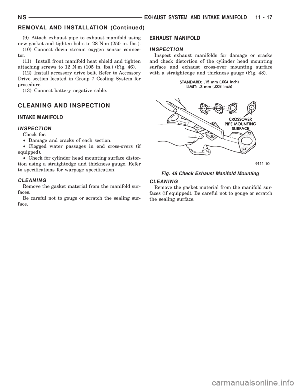
Inspect exhaust manifolds for damage or cracks
and check distortion of the cylinder head mounting
surface and exhaust cross-over mounting surface
with a straightedge and thickness gauge (Fig. 48).
CLEANING
Remove the gasket material from the manifold sur-
faces (if equipped). Be careful not to gouge or scratch
the sealing surface.
Fig. 48 Check Exhaust Manifold Mounting
NSEXHAUST SYSTEM AND INTAKE MANIFOLD 11 - 17
REMOVAL AND INSTALLATION (Continued)
Page 1283 of 1938
FRAME
INDEX
page page
REMOVAL AND INSTALLATION
FRONT CROSSMEMBER MOUNT BUSHINGS . . . 5
FRONT CROSSMEMBER................... 3SPECIFICATIONS
FRAME AND BODY OPENING DIMENSIONS.... 5
REMOVAL AND INSTALLATION
FRONT CROSSMEMBER
The front suspension crossmember must be
installed in the design location to achieve proper
front end suspension alignment. If the crossmember
is removed without applying reference marks on the
frame rails, align the crossmember according to the
dimensions provided in this group.
NOTE: If the caged nuts in the frame rails become
damaged and cannot be reused, a replacement nut
can be obtained through a MoparTParts supplier.
REMOVAL
(1) Disconnect battery negative cable.
(2) Remove steering column lower cover from
instrument panel. Refer to Group 8E, Instrument
Panel and Systems.
(3) Remove knee blocker reinforcement. Refer to
Group 8E, Instrument Panel and Systems.
(4) Position steering so front wheels are straight
ahead.
CAUTION: Do not rotate steering wheel after disen-
gaging lower coupling from steering gear, damage
to airbag clock spring can result.
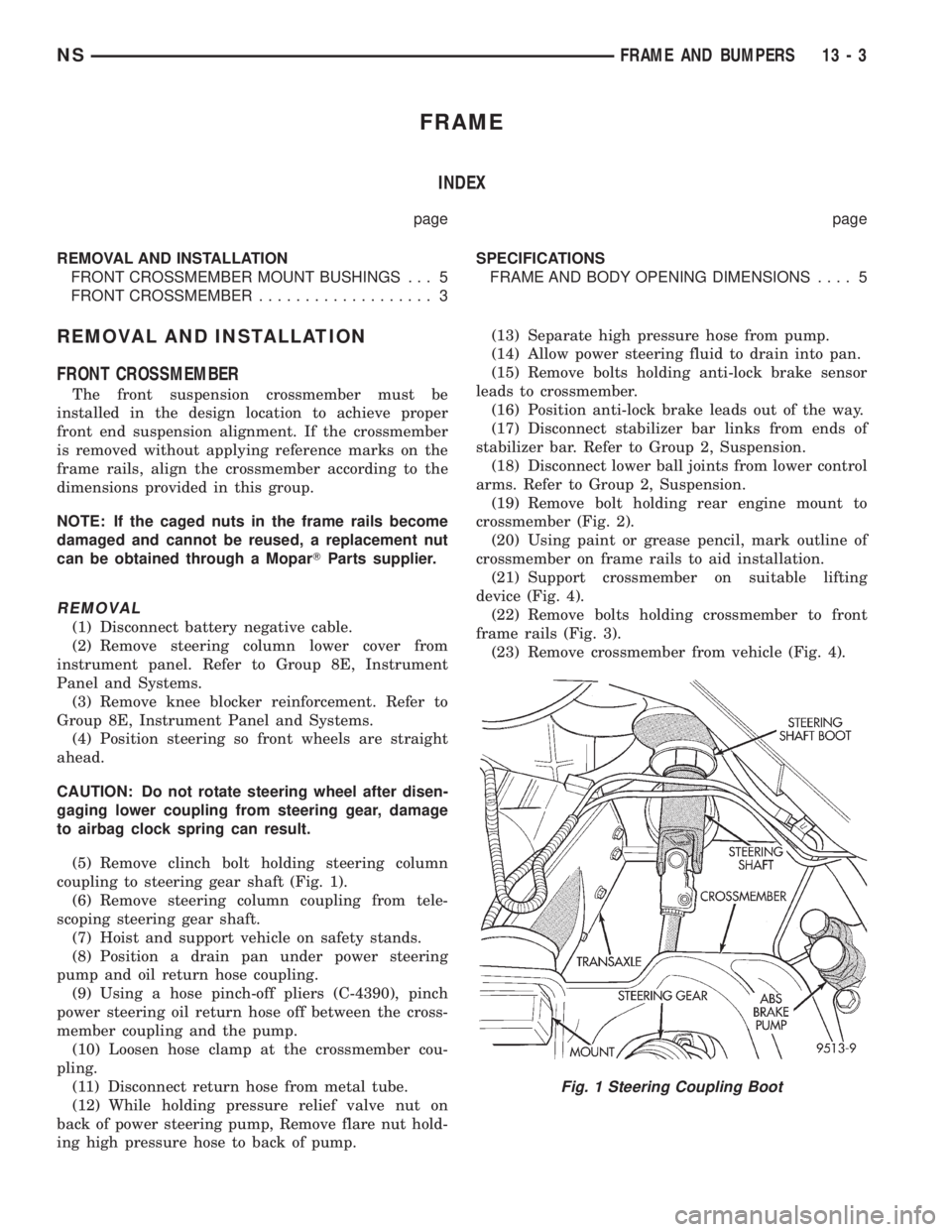
(5) Remove clinch bolt holding steering column
coupling to steering gear shaft (Fig. 1).
(6) Remove steering column coupling from tele-
scoping steering gear shaft.
(7) Hoist and support vehicle on safety stands.
(8) Position a drain pan under power steering
pump and oil return hose coupling.
(9) Using a hose pinch-off pliers (C-4390), pinch
power steering oil return hose off between the cross-
member coupling and the pump.
(10) Loosen hose clamp at the crossmember cou-
pling.
(11) Disconnect return hose from metal tube.
(12) While holding pressure relief valve nut on
back of power steering pump, Remove flare nut hold-
ing high pressure hose to back of pump.(13) Separate high pressure hose from pump.
(14) Allow power steering fluid to drain into pan.
(15) Remove bolts holding anti-lock brake sensor
leads to crossmember.
(16) Position anti-lock brake leads out of the way.
(17) Disconnect stabilizer bar links from ends of
stabilizer bar. Refer to Group 2, Suspension.
(18) Disconnect lower ball joints from lower control
arms. Refer to Group 2, Suspension.
(19) Remove bolt holding rear engine mount to
crossmember (Fig. 2).
(20) Using paint or grease pencil, mark outline of
crossmember on frame rails to aid installation.
(21) Support crossmember on suitable lifting
device (Fig. 4).
(22) Remove bolts holding crossmember to front
frame rails (Fig. 3).
(23) Remove crossmember from vehicle (Fig. 4).
Fig. 1 Steering Coupling Boot
NSFRAME AND BUMPERS 13 - 3
Page 1285 of 1938
(7) Connect lower ball joints to lower control arms.
Refer to Group 2, Suspension.
(8) Connect stabilizer bar links to ends of stabi-
lizer bar. Refer to Group 2, Suspension.
(9) Install bolts to hold anti-lock brake sensor
leads to crossmember.
(10) Install high pressure hose to pump.
(11) Connect return hose to metal tube.
(12) Tighten hose clamp at the crossmember cou-
pling.
(13) Remove pinch-off pliers.
(14) Position steering so front wheels are straight
ahead.
(15) Install steering column coupling to telescoping
steering gear shaft.
(16) Install clinch bolt to hold steering column cou-
pling to steering gear shaft.
(17) Install knee blocker reinforcement. Refer to
Group 8E, Instrument Panel and Systems.
(18) Install steering column lower cover from
instrument panel. Refer to Group 8E, Instrument
Panel and Systems.
(19) Connect battery negative cable.
FRONT CROSSMEMBER MOUNT BUSHINGS
REMOVAL
(1) Using paint or grease pencil, mark outline of
crossmember on frame rails.
(2) Loosen bolts holding crossmember to frame
rails.
(3) Remove bolt on bushing that requires replace-
ment.
(4) Allow crossmember to drop down enough to
gain clearance for bushing removal.
(5) Remove bushing from vehicle.
INSTALLATION
(1) Apply rubber lube or soap to replacement bush-
ing.(2) Insert lower half of bushing into square hole in
crossmember.
(3) Place upper half of bushing on top of cross-
member aligned to receive square tube protruding
upward from lower bushing half.
(4) Squeeze bushing halves together to ensure they
are properly mated.
(5) Lift crossmember upward to close gap between
the bushing and frame.
(6) Verify that lower bushing is fully seated into
crossmember and upper bushing.
(7) Install bolt to hold bushing and crossmember
to frame rail hand tight.
(8) Align crossmember to reference marks on
frame rails.
(9) Tighten crossmember to frame rails attaching
bolts to 163 N´m (120 ft. lbs.) torque.
SPECIFICATIONS
FRAME AND BODY OPENING DIMENSIONS
Frame dimensions are listed in metric scale. All
dimensions are from center to center of Principal
Locating Point (PLP), or from center to center of PLP
and fastener location.
VEHICLE PREPARATION
Position the vehicle on a frame alignment rack,
refer to instructions provided with equipment being
used. Adjust the vehicle PLP heights to the specified
dimension above the work surface (datum line). Ver-
tical dimensions can be taken from the datum line to
the locations indicated were applicable. Refer to (Fig.
5), (Fig. 6), (Fig. 7), (Fig. 8), (Fig. 9), (Fig. 10) and
(Fig. 11) for proper dimensions.
NSFRAME AND BUMPERS 13 - 5
REMOVAL AND INSTALLATION (Continued)