sensor CHRYSLER VOYAGER 1996 Service Manual
[x] Cancel search | Manufacturer: CHRYSLER, Model Year: 1996, Model line: VOYAGER, Model: CHRYSLER VOYAGER 1996Pages: 1938, PDF Size: 55.84 MB
Page 1188 of 1938
HYDRAULIC LASH ADJUSTER NOISE
A tappet-like noise may be produced from several
items. Refer to Lash Adjuster Noise - Diagnosis in
Standard Service Procedures, outlined in this Group.
Lash adjusters are replaced with the rocker
arm as an assembly.
VALVE SEALS AND SPRINGS IN VEHICLE
REMOVAL
(1) Remove rocker arm shafts assemblies as previ-
ously outlined in this section.
(2) Rotate crankshaft until piston is at TDC on
compression.
(3) With air hose attached to adapter tool installed
in spark plug hole, apply 90-120 psi air pressure.
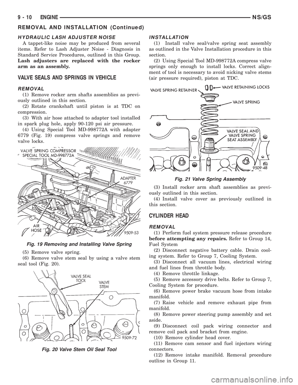
(4) Using Special Tool MD-998772A with adapter
6779 (Fig. 19) compress valve springs and remove
valve locks.
(5) Remove valve spring.
(6) Remove valve stem seal by using a valve stem
seal tool (Fig. 20).
INSTALLATION
(1) Install valve seal/valve spring seat assembly
as outlined in the Valve Installation procedure in this
section.
(2) Using Special Tool MD-998772A compress valve
springs only enough to install locks. Correct align-
ment of tool is necessary to avoid nicking valve stems
(air pressure required), piston at TDC.
(3) Install rocker arm shaft assemblies as previ-
ously outlined in this section.
(4) Install valve cover as previously outlined in
this section.
CYLINDER HEAD
REMOVAL
(1) Perform fuel system pressure release procedure
before attempting any repairs.Refer to Group 14,
Fuel System
(2) Disconnect negative battery cable. Drain cool-
ing system. Refer to Group 7, Cooling System.
(3) Disconnect all vacuum lines, electrical wiring
and fuel lines from throttle body.
(4) Remove throttle linkage.
(5) Remove accessory drive belts. Refer to Group 7,
Cooling System for procedure.
(6) Remove power brake vacuum hose from intake
manifold.
(7) Raise vehicle and remove exhaust pipe from
manifold.
(8) Remove power steering pump assembly and set
aside.
(9) Disconnect coil pack wiring connector and
remove coil pack and bracket from engine.
(10) Remove cylinder head cover.
(11) Remove cam sensor and fuel injectors wiring
connectors.
(12) Remove intake manifold. Removal procedure
outline in Group 11.
Fig. 19 Removing and Installing Valve Spring
Fig. 20 Valve Stem Oil Seal Tool
Fig. 21 Valve Spring Assembly
9 - 10 ENGINENS/GS
REMOVAL AND INSTALLATION (Continued)
Page 1214 of 1938
Valve Margin
Intake.....1.15 ± 1.48 mm (0.0452 ± 0.0582 in.)
Exhaust....1.475 ± 1.805 mm (0.058 ± 0.071 in.)
Valve Length (Overall)
Intake....114.69 ± 115.19 mm (4.515 ± 4.535 in.)
Exhaust . . 109.59 ± 110.09 mm (4.603 ± 4.623 in.)
Valve Stem Tip Height
Intake.......45.01 ± 46.07 mm (1.77 ± 1.81 in.)
Exhaust......43.51 ± 44.57 mm (1.71 ± 1.75 in.)
Stem Diameter
Intake.....5.934 ± 5.952 mm (0.234 ± 0.234 in.)
Exhaust....5.906 ± 5.924 mm (0.233 ± 0.233 in.)
Stem to Guide Clearance
Intake . . . 0.048 ± 0.066 mm (0.0018 ± 0.0025 in.)
Exhaust . 0.0736 ± 0.094 mm (0.0029 ± 0.0037 in.)
Max. Allowable Intake.....0.076 mm (0.003 in.)
Max. Allowable Exhaust....0.101 mm (0.004 in.)
Valve Springs
Free Length (Approx.)......44.4 mm (1.747 in.)
Nominal Force (Valve closed) . 91 N´m @ 39.8 mm
(67 ft. lbs. @ 1.57 in.)
Nominal Force (Valve open) . 239 N´m @ 32.6 mm
(176 lbs. @ 1.28 in.)
Installed Height..........40.18 mm (1.580 in.)
* SERVICE AS AN ASSEMBLY WITH ROCKER
ARM.
** ALL READINGS IN CRANKSHAFT DEGREES,
AT 0.5 mm (0.019 in.) OF VALVE LIFT.
TORQUE CHART 2.0L SOHC
DESCRIPTION...................TORQUE
Camshaft Sensor Pick Up
Bolts...................9.6N´m(85in.lbs.)
Camshaft Sprocket
Bolt....................115N´m(85ft.lbs.)
Connecting Rod Cap
Bolts.........27N´m(20ft.lbs.) Plus 1/4 Turn
CollarÐOil Pan to Transaxle
Step 1: Collar to Oil Pan Bolts . 3 N´m (30 in. lbs.)
Step 2: Collar to Transaxle
Bolts...................108N´m(80ft.lbs.)
Step 3: Collar to Oil Pan
Bolts....................54N´m(40ft.lbs.)
Crankshaft Main Bearing Cap/Bedplate
M8 Bedplate Bolts..........30N´m(22ft.lbs.)
M11 Main Cap Bolts........81N´m(60ft.lbs.)
Crankshaft Damper
Bolt...................142N´m(105 ft. lbs.)
Cylinder Head
Bolts.......Refer To Cylinder Head Installation
Cylinder Head Cover
Bolts...................12N´m(105 in. lbs.)
Engine Mount BracketÐRight
Bolts....................61N´m(45ft.lbs.)DESCRIPTION...................TORQUE
Engine Mounting
Bolts.......Refer to Engine Mount Installation
Exhaust Manifold to Cylinder Head
Bolts...................23N´m(200 in. lbs.)
Exhaust Manifold Heat Shield
Bolts...................12N´m(105 in. lbs.)
Intake Manifold
Bolts...................12N´m(105 in. lbs.)
Oil Filter Adapter
Fastener.................80N´m(60ft.lbs.)
Oil Filter.................20N´m(15ft.lbs.)
Oil Pan
Bolts...................12N´m(105 in. lbs.)
Drain Plug...............27N´m(20ft.lbs.)
Oil Pump Attaching
Bolts...................28N´m(250 in. lbs.)
Oil Pump Cover Fastener . . . 12 N´m (105 in. lbs.)
Oil Pump Pick-up Tube Bolt . 28 N´m (250 in. lbs.)
Oil Pump Relief Valve Cap . . . 41 N´m (30 ft. lbs.)
Rocker Arm Shaft
Bolts...................28N´m(250 in. lbs.)
Spark Plugs...............28N´m(20ft.lbs.)
Thermostat Housing
Bolts...................23N´m(200 in lbs.)
Timing Belt Cover
Bolts M6................12N´m(105 in. lbs.)
Timing Belt Mechanical Tensioner Assembly
Bolts...................28N´m(250 in. lbs.)
Timing Belt Hydraulic Tensioner
Pulley Bolt...............68N´m(50ft.lbs.)
Pivot Bracket Bolt..........31N´m(23ft.lbs.)
Tensioner Bolts............31N´m(23ft.lbs.)
Water Pump Mounting
Bolts...................12N´m(105 in. lbs.)
SPECIAL TOOLS
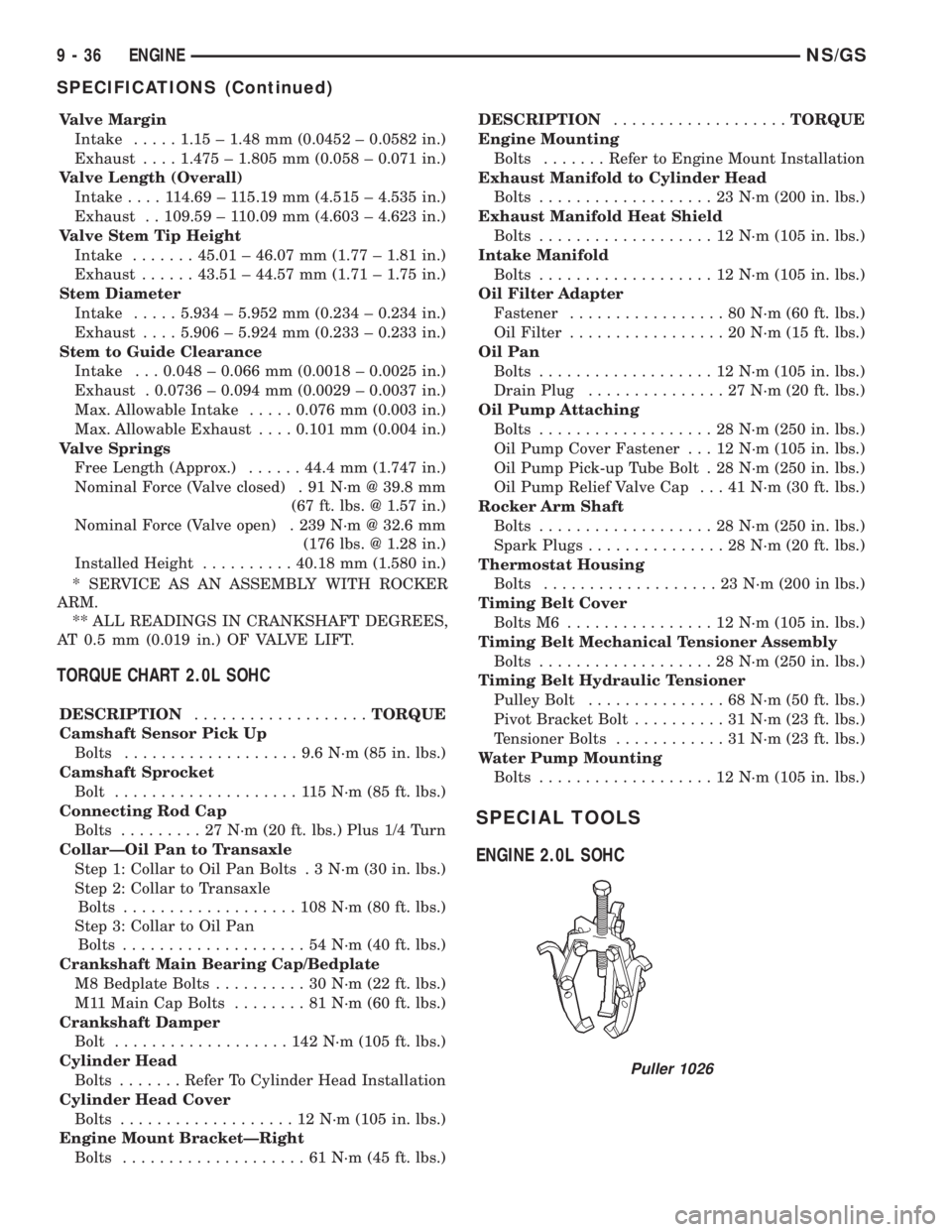
ENGINE 2.0L SOHC
Puller 1026
9 - 36 ENGINENS/GS
SPECIFICATIONS (Continued)
Page 1221 of 1938
DIAGNOSIS AND TESTING
ENGINE DIAGNOSISÐPERFORMANCE
CONDITION POSSIBLE CAUSES CORRECTION
ENGINE WILL NOT
CRANK OR CRANKS
SLOWLY1. Starting motor operating, but not cranking the
engine.1. Remove the starter motor. Check for broken
flywheel teeth or a broken starter motor spring.
2. Crankshaft rotation restricted. 2. Rotate the engine to check for rotational
resistance.
3. Starting circuit connections loose or corroded. 3. Clean and tighten connections.
4. Neutral safety or starter relay inoperative. 4. Check starter relay supply voltage and proper
operation of neutral safety switch (if equipped).
Replace defective parts.
5. Battery charge low. 5. Check Battery voltage. Replace battery if a
charge cannot be held.
6. No voltage to starter solenoid. 6. Check voltage to solenoid. If necessary, replace
the solenoid.
7. Solenoid or starter motor inoperative. 7. Replace starter motor.
ENGINE CRANKS, BUT
WILL NOT START, NO
SMOKE1. No fuel in supply tank. 1. Fill fuel supply.
2. Electrical fuel shutdown solenoid not operating. 2. Check for loose wires and verify that the fuel
shutdown solenoid is functioning. Check for fault
codes in the ECU.
3. Fuel injection system defective: Cranking speed
sensor. Loose connection between ECU and
harness. No power supply to the ECU. Loose
connection between injection pump and harness.3. Check for fault codes at ECU. Refer to Group 14,
Fuel System for repairs procedures.
4. Air intake or exhaust plugged. 4. Remove the obstruction.
5. Fuel filter plugged. 5. Drain fuel/water separator and replace fuel filter.
6. Excessive fuel inlet restriction. 6. Check for restriction. Correct cause.
7. Injection pump not getting fuel or fuel is aerated. 7. Check fuel flow/bleed fuel system.
8. One or more injectors worn or not operating
properly.8. Check/replace bad or improperly operating
injectors.
9. Camshaft out of time. 9. Check/correct timing chain sprocket alignment.
ENGINE HARD TO
START, OR WILL NOT
START, SMOKE FROM
EXHAUST1. Incorrect starting procedure. 1. The fuel shutoff solenoid control must be in the
run position. Ensure the proper procedure is being
used.
2. Cranking speed to slow. 2. Check the battery, starter motor and look for
loose or corroded wiring connections.
3. Cylinder head heater plugs defective. 3. Verify system is working. Verify connection
between heater plug relay and ECU. Repair/replace
inoperative parts.
4. Insufficient intake air 4. Inspect or replace air filter and check for
obstruction in air supply.
5. Air in fuel system or the fuel supply is
inadequate.5. Check the fuel flow through the filter and bleed
system. Locate and eliminate the air source.
6. Contaminated fuel. 6. Verify by operating the engine with clean fuel
from a temporary tank. Check for the presence of
gasoline. Drain and flush fuel supply tank. Replace
fuel/water separator filter.
7. Fuel screen plugged. 7. Check fuel screen.
8. One or more injectors worn or not operating
properly.8. Check/replace improperly operating injectors.
9. Injector pump out of time. 9. Check pump timing. Refer to Group 14, Fuel
System for procedure.
10. Engine compression low. 10. Check compression to identify the problem.
11. Fuel injection system defective. 11. Vacuum modulator defective causing EGR to
open in cold condition. Check for fault codes in the
ECU.
NS/GSENGINE 9 - 43
Page 1231 of 1938
ENGINE ASSEMBLY
REMOVAL
(1) Disconnect the battery.
(2) Remove the air cleaner assembly and inlet
hose.
(3) Remove both hoses at intercooler and engine.
(4) Disconnect EGR vacuum hose.
(5) Disconnect brake booster vacuum hose.
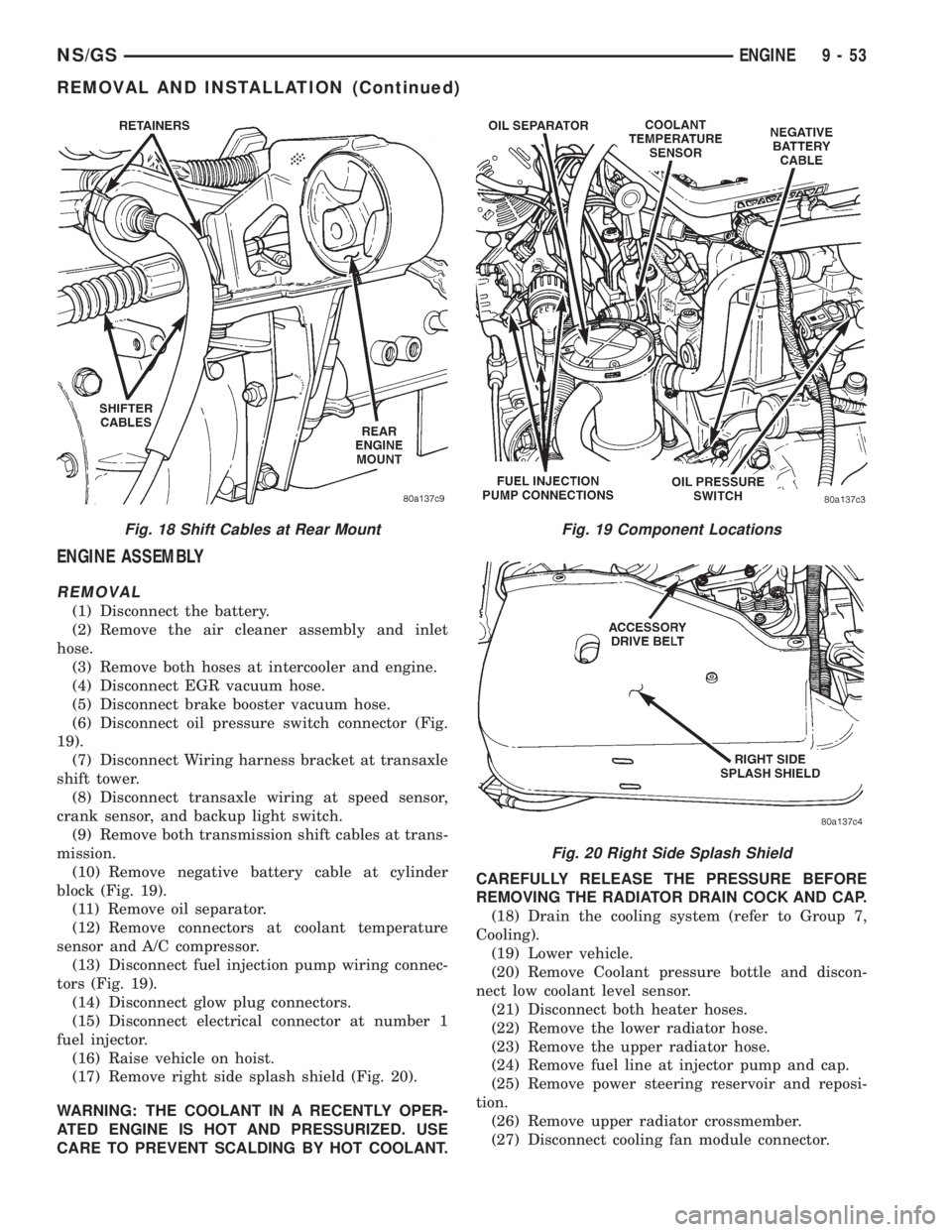
(6) Disconnect oil pressure switch connector (Fig.
19).
(7) Disconnect Wiring harness bracket at transaxle
shift tower.
(8) Disconnect transaxle wiring at speed sensor,
crank sensor, and backup light switch.
(9) Remove both transmission shift cables at trans-
mission.
(10) Remove negative battery cable at cylinder
block (Fig. 19).
(11) Remove oil separator.
(12) Remove connectors at coolant temperature
sensor and A/C compressor.
(13) Disconnect fuel injection pump wiring connec-
tors (Fig. 19).
(14) Disconnect glow plug connectors.
(15) Disconnect electrical connector at number 1
fuel injector.
(16) Raise vehicle on hoist.
(17) Remove right side splash shield (Fig. 20).
WARNING: THE COOLANT IN A RECENTLY OPER-
ATED ENGINE IS HOT AND PRESSURIZED. USE
CARE TO PREVENT SCALDING BY HOT COOLANT.CAREFULLY RELEASE THE PRESSURE BEFORE
REMOVING THE RADIATOR DRAIN COCK AND CAP.
(18) Drain the cooling system (refer to Group 7,
Cooling).
(19) Lower vehicle.
(20) Remove Coolant pressure bottle and discon-
nect low coolant level sensor.
(21) Disconnect both heater hoses.
(22) Remove the lower radiator hose.
(23) Remove the upper radiator hose.
(24) Remove fuel line at injector pump and cap.
(25) Remove power steering reservoir and reposi-
tion.
(26) Remove upper radiator crossmember.
(27) Disconnect cooling fan module connector.
Fig. 18 Shift Cables at Rear MountFig. 19 Component Locations
Fig. 20 Right Side Splash Shield
NS/GSENGINE 9 - 53
REMOVAL AND INSTALLATION (Continued)
Page 1235 of 1938
(22) Remove the injector sensor wire at the con-
nector, and glow plug Connectors.
NOTE: The attachment point for the injector sensor
wire at the injector is not a connector. The connec-
tor is located in the wire 4 to 6 inches away from
the injector.
(23) Remove injector fuel lines from injectors to
pump.
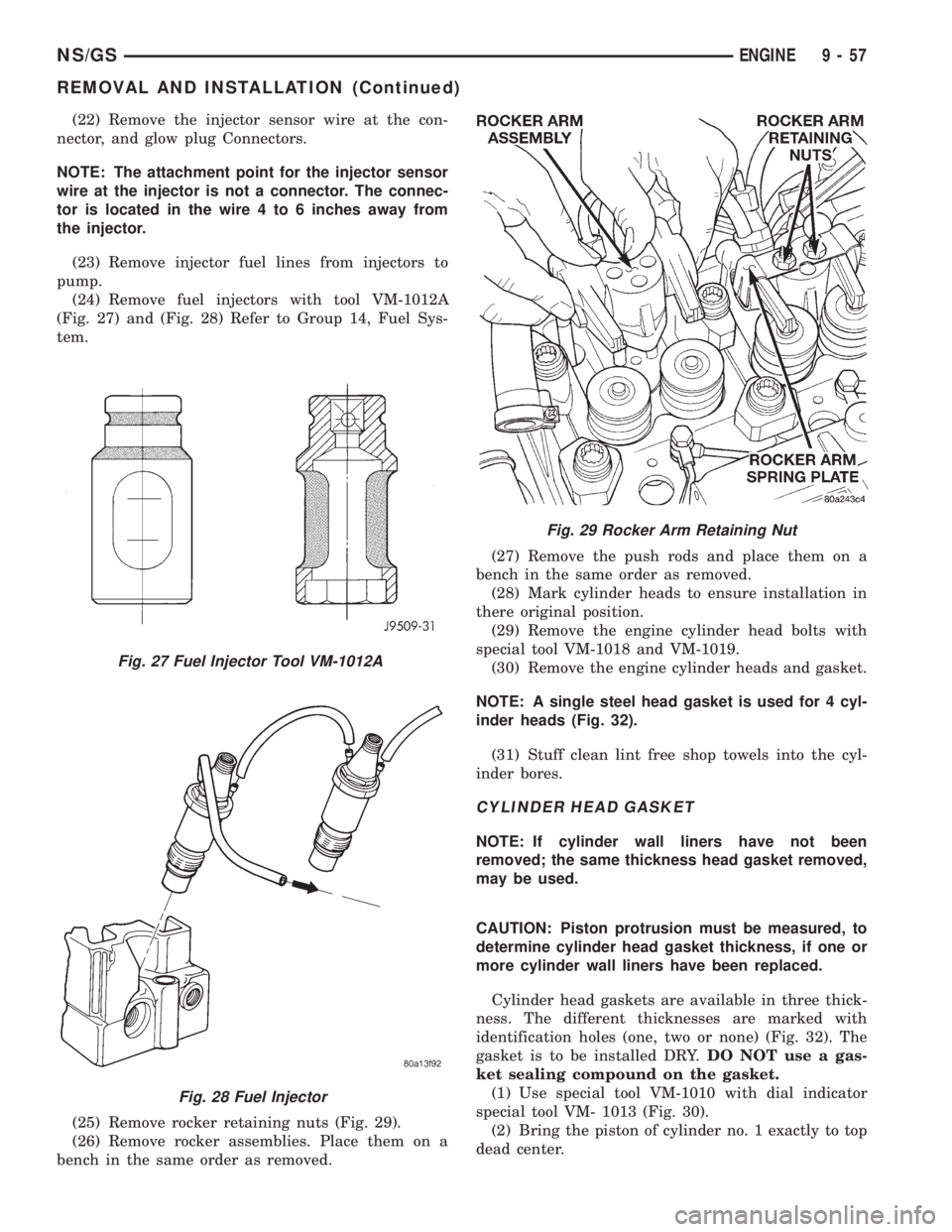
(24) Remove fuel injectors with tool VM-1012A
(Fig. 27) and (Fig. 28) Refer to Group 14, Fuel Sys-
tem.
(25) Remove rocker retaining nuts (Fig. 29).
(26) Remove rocker assemblies. Place them on a
bench in the same order as removed.(27) Remove the push rods and place them on a
bench in the same order as removed.
(28) Mark cylinder heads to ensure installation in
there original position.
(29) Remove the engine cylinder head bolts with
special tool VM-1018 and VM-1019.
(30) Remove the engine cylinder heads and gasket.
NOTE: A single steel head gasket is used for 4 cyl-
inder heads (Fig. 32).
(31) Stuff clean lint free shop towels into the cyl-
inder bores.
CYLINDER HEAD GASKET
NOTE: If cylinder wall liners have not been
removed; the same thickness head gasket removed,
may be used.
CAUTION: Piston protrusion must be measured, to
determine cylinder head gasket thickness, if one or
more cylinder wall liners have been replaced.
Cylinder head gaskets are available in three thick-
ness. The different thicknesses are marked with
identification holes (one, two or none) (Fig. 32). The
gasket is to be installed DRY.DO NOT use a gas-
ket sealing compound on the gasket.
(1) Use special tool VM-1010 with dial indicator
special tool VM- 1013 (Fig. 30).
(2) Bring the piston of cylinder no. 1 exactly to top
dead center.
Fig. 27 Fuel Injector Tool VM-1012A
Fig. 28 Fuel Injector
Fig. 29 Rocker Arm Retaining Nut
NS/GSENGINE 9 - 57
REMOVAL AND INSTALLATION (Continued)
Page 1237 of 1938
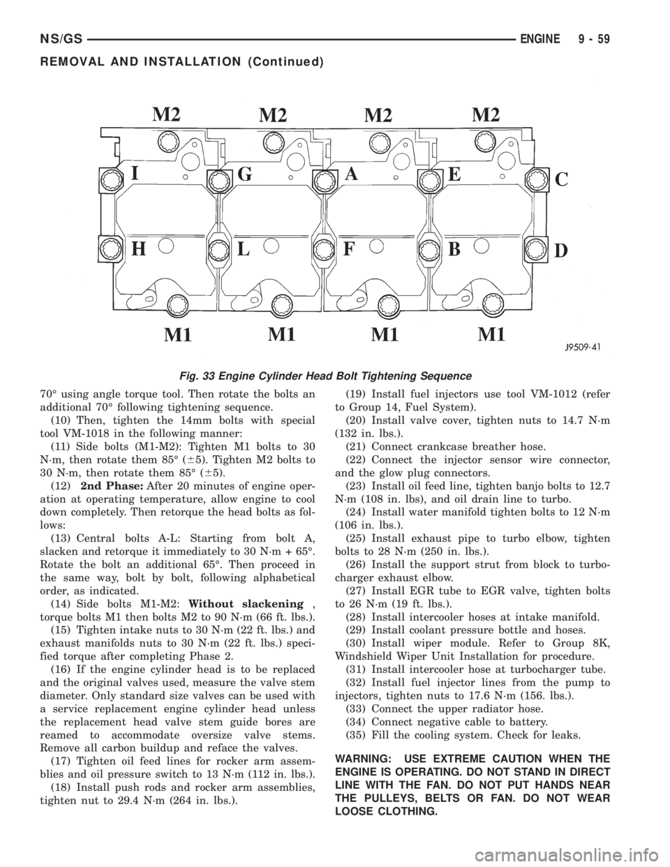
70É using angle torque tool. Then rotate the bolts an
additional 70É following tightening sequence.
(10) Then, tighten the 14mm bolts with special
tool VM-1018 in the following manner:
(11) Side bolts (M1-M2): Tighten M1 bolts to 30
N´m, then rotate them 85É (65). Tighten M2 bolts to
30 N´m, then rotate them 85É (65).
(12)2nd Phase:After 20 minutes of engine oper-
ation at operating temperature, allow engine to cool
down completely. Then retorque the head bolts as fol-
lows:
(13) Central bolts A-L: Starting from bolt A,
slacken and retorque it immediately to 30 N´m + 65É.
Rotate the bolt an additional 65É. Then proceed in
the same way, bolt by bolt, following alphabetical
order, as indicated.
(14) Side bolts M1-M2:Without slackening,
torque bolts M1 then bolts M2 to 90 N´m (66 ft. lbs.).
(15) Tighten intake nuts to 30 N´m (22 ft. lbs.) and
exhaust manifolds nuts to 30 N´m (22 ft. lbs.) speci-
fied torque after completing Phase 2.
(16) If the engine cylinder head is to be replaced
and the original valves used, measure the valve stem
diameter. Only standard size valves can be used with
a service replacement engine cylinder head unless
the replacement head valve stem guide bores are
reamed to accommodate oversize valve stems.
Remove all carbon buildup and reface the valves.
(17) Tighten oil feed lines for rocker arm assem-
blies and oil pressure switch to 13 N´m (112 in. lbs.).
(18) Install push rods and rocker arm assemblies,
tighten nut to 29.4 N´m (264 in. lbs.).(19) Install fuel injectors use tool VM-1012 (refer
to Group 14, Fuel System).
(20) Install valve cover, tighten nuts to 14.7 N´m
(132 in. lbs.).
(21) Connect crankcase breather hose.
(22) Connect the injector sensor wire connector,
and the glow plug connectors.
(23) Install oil feed line, tighten banjo bolts to 12.7
N´m (108 in. lbs), and oil drain line to turbo.
(24) Install water manifold tighten bolts to 12 N´m
(106 in. lbs.).
(25) Install exhaust pipe to turbo elbow, tighten
bolts to 28 N´m (250 in. lbs.).
(26) Install the support strut from block to turbo-
charger exhaust elbow.
(27) Install EGR tube to EGR valve, tighten bolts
to 26 N´m (19 ft. lbs.).
(28) Install intercooler hoses at intake manifold.
(29) Install coolant pressure bottle and hoses.
(30) Install wiper module. Refer to Group 8K,
Windshield Wiper Unit Installation for procedure.
(31) Install intercooler hose at turbocharger tube.
(32) Install fuel injector lines from the pump to
injectors, tighten nuts to 17.6 N´m (156. lbs.).
(33) Connect the upper radiator hose.
(34) Connect negative cable to battery.
(35) Fill the cooling system. Check for leaks.
WARNING: USE EXTREME CAUTION WHEN THE
ENGINE IS OPERATING. DO NOT STAND IN DIRECT
LINE WITH THE FAN. DO NOT PUT HANDS NEAR
THE PULLEYS, BELTS OR FAN. DO NOT WEAR
LOOSE CLOTHING.
Fig. 33 Engine Cylinder Head Bolt Tightening Sequence
NS/GSENGINE 9 - 59
REMOVAL AND INSTALLATION (Continued)
Page 1266 of 1938
REMOVAL AND INSTALLATION
EXHAUST PIPES, MUFFLERS AND TAILPIPES
REMOVAL
(1) Raise vehicle on hoist and apply penetrating
oil to clamp bolts and nuts of component being
removed.
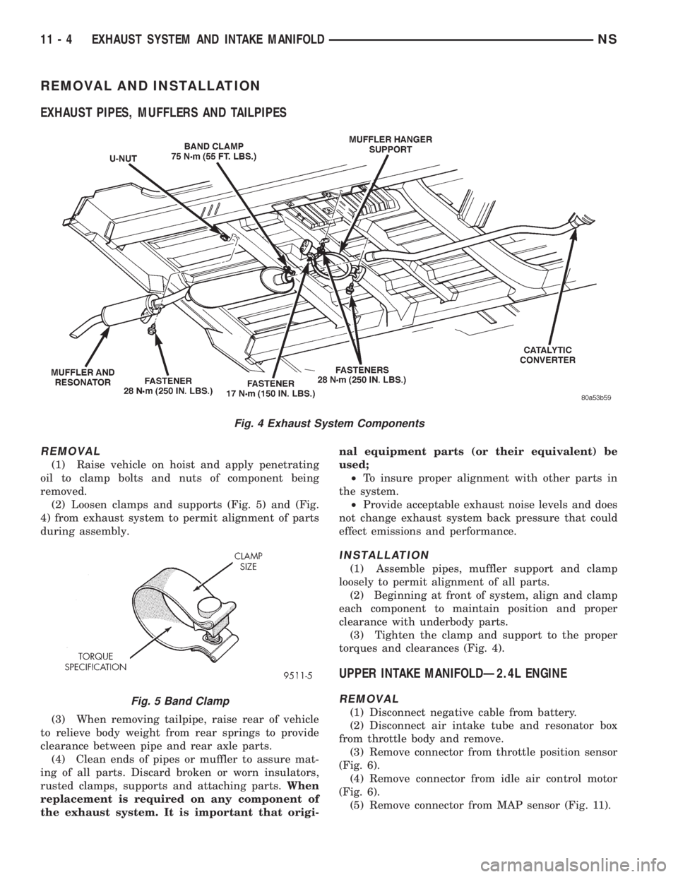
(2) Loosen clamps and supports (Fig. 5) and (Fig.
4) from exhaust system to permit alignment of parts
during assembly.
(3) When removing tailpipe, raise rear of vehicle
to relieve body weight from rear springs to provide
clearance between pipe and rear axle parts.
(4) Clean ends of pipes or muffler to assure mat-
ing of all parts. Discard broken or worn insulators,
rusted clamps, supports and attaching parts.When
replacement is required on any component of
the exhaust system. It is important that origi-nal equipment parts (or their equivalent) be
used;
²To insure proper alignment with other parts in
the system.
²Provide acceptable exhaust noise levels and does
not change exhaust system back pressure that could
effect emissions and performance.
INSTALLATION
(1) Assemble pipes, muffler support and clamp
loosely to permit alignment of all parts.
(2) Beginning at front of system, align and clamp
each component to maintain position and proper
clearance with underbody parts.
(3) Tighten the clamp and support to the proper
torques and clearances (Fig. 4).
UPPER INTAKE MANIFOLDÐ2.4L ENGINE
REMOVAL
(1) Disconnect negative cable from battery.
(2) Disconnect air intake tube and resonator box
from throttle body and remove.
(3) Remove connector from throttle position sensor
(Fig. 6).
(4) Remove connector from idle air control motor
(Fig. 6).
(5) Remove connector from MAP sensor (Fig. 11).
Fig. 4 Exhaust System Components
Fig. 5 Band Clamp
11 - 4 EXHAUST SYSTEM AND INTAKE MANIFOLDNS
Page 1268 of 1938
INSTALLATION
(1) Install new upper intake manifold gasket.
NOTE: Center outboard fastener is a double stud.
(2) Tighten upper intake manifold fasteners start-
ing at center and progressing outward in both direc-
tions. Tighten bolts to 28 N´m (250 in. lbs.). Repeat
this procedures until all fasteners are at specified
torque.
(3) Install dipstick tube. Seal tube to cylinder
block using MopartStud N' Bearing Mount Adhe-
sive. Tighten dipstick tube fastener to 12 N´m (105
in. lbs.)
(4) Install dipstick.
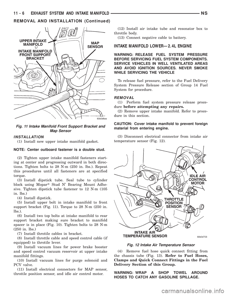
(5) Install upper bolt in intake manifold to front
support bracket (Fig. 11). Torque to 28 N´m (250 in.
lbs.).
(6) Install two top bolts at intake manifold to rear
support bracket making sure bracket to manifold
spacer is in place (Fig. 10). Tighten bolts to 28 N´m
(250 in. lbs.)
(7) Install throttle cables in bracket.
(8) Install throttle cable and speed control cable (if
equipped) to throttle lever.
(9) Install vacuum lines for power brake booster
and speed control vacuum reservoir at upper intake
manifold fittings.
(10) Install vacuum lines for purge solenoid and
PCV valve.
(11) Install electrical connectors for MAP sensor,
throttle position sensor, and idle air control motor.(12) Install air intake tube and resonator box to
throttle body.
(13) Connect negative cable to battery.
INTAKE MANIFOLD LOWERÐ2.4L ENGINE
WARNING: RELEASE FUEL SYSTEM PRESSURE
BEFORE SERVICING FUEL SYSTEM COMPONENTS.
SERVICE VEHICLES IN WELL VENTILATED AREAS
AND AVOID IGNITION SOURCES. NEVER SMOKE
WHILE SERVICING THE VEHICLE
To release fuel pressure, refer to the Fuel Delivery
System Pressure Release section of Group 14 Fuel
System for procedure.
REMOVAL
(1) Perform fuel system pressure release proce-
durebefore attempting any repairs.
(2) Remove upper intake manifold. Refer to proce-
dure in this section.
CAUTION: Cover intake manifold to prevent foreign
material from entering engine.
(3) Disconnect electrical connector from intake air
temperature sensor (Fig. 12).
(4) Remove fuel hose quick connect fitting from
the chassis tube (Fig. 13).Refer to Fuel Hoses,
Clamps and Quick Connect Fittings in the Fuel
Delivery Section of this Group.
WARNING: WRAP A SHOP TOWEL AROUND
HOSES TO CATCH ANY GASOLINE SPILLAGE.
Fig. 11 Intake Manifold Front Support Bracket and
Map Sensor
Fig. 12 Intake Air Temperature Sensor
11 - 6 EXHAUST SYSTEM AND INTAKE MANIFOLDNS
REMOVAL AND INSTALLATION (Continued)
Page 1269 of 1938
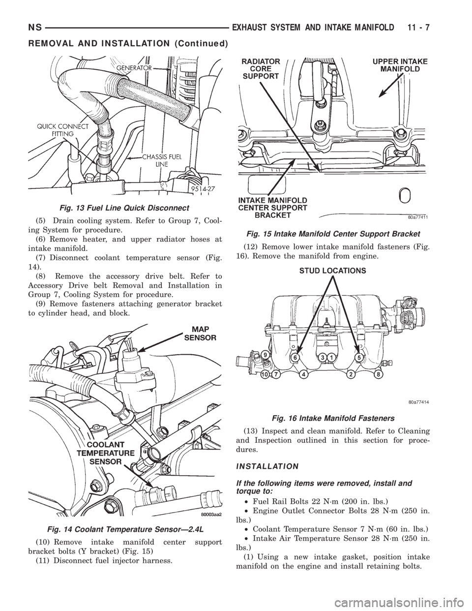
(5) Drain cooling system. Refer to Group 7, Cool-
ing System for procedure.
(6) Remove heater, and upper radiator hoses at
intake manifold.
(7) Disconnect coolant temperature sensor (Fig.
14).
(8) Remove the accessory drive belt. Refer to
Accessory Drive belt Removal and Installation in
Group 7, Cooling System for procedure.
(9) Remove fasteners attaching generator bracket
to cylinder head, and block.
(10) Remove intake manifold center support
bracket bolts (Y bracket) (Fig. 15)
(11) Disconnect fuel injector harness.(12) Remove lower intake manifold fasteners (Fig.
16). Remove the manifold from engine.
(13) Inspect and clean manifold. Refer to Cleaning
and Inspection outlined in this section for proce-
dures.
INSTALLATION
If the following items were removed, install and
torque to:
²Fuel Rail Bolts 22 N´m (200 in. lbs.)
²Engine Outlet Connector Bolts 28 N´m (250 in.
lbs.)
²Coolant Temperature Sensor 7 N´m (60 in. lbs.)
²Intake Air Temperature Sensor 28 N´m (250 in.
lbs.)
(1) Using a new intake gasket, position intake
manifold on the engine and install retaining bolts.
Fig. 13 Fuel Line Quick Disconnect
Fig. 14 Coolant Temperature SensorÐ2.4L
Fig. 15 Intake Manifold Center Support Bracket
Fig. 16 Intake Manifold Fasteners
NSEXHAUST SYSTEM AND INTAKE MANIFOLD 11 - 7
REMOVAL AND INSTALLATION (Continued)
Page 1270 of 1938
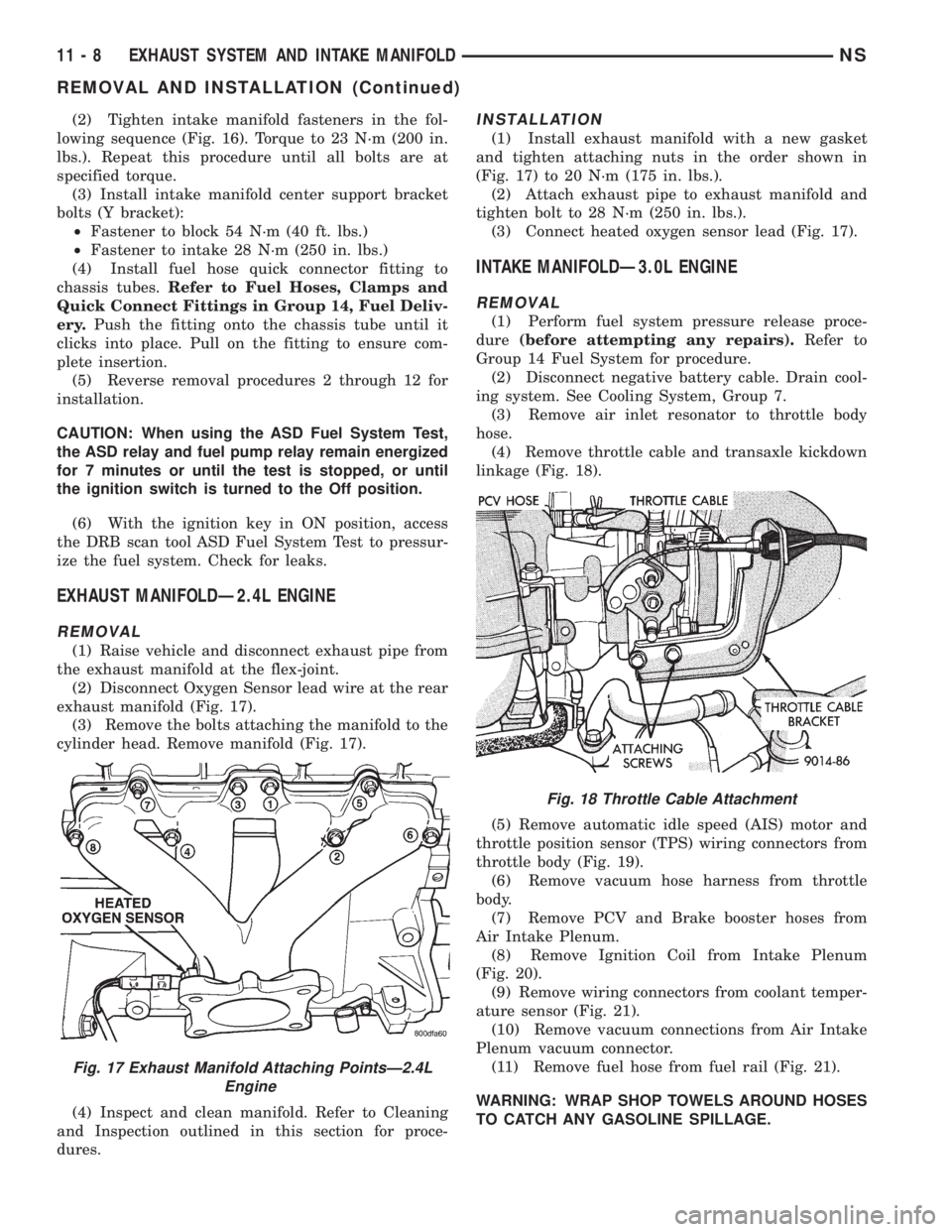
(2) Tighten intake manifold fasteners in the fol-
lowing sequence (Fig. 16). Torque to 23 N´m (200 in.
lbs.). Repeat this procedure until all bolts are at
specified torque.
(3) Install intake manifold center support bracket
bolts (Y bracket):
²Fastener to block 54 N´m (40 ft. lbs.)
²Fastener to intake 28 N´m (250 in. lbs.)
(4) Install fuel hose quick connector fitting to
chassis tubes.Refer to Fuel Hoses, Clamps and
Quick Connect Fittings in Group 14, Fuel Deliv-
ery.Push the fitting onto the chassis tube until it
clicks into place. Pull on the fitting to ensure com-
plete insertion.
(5) Reverse removal procedures 2 through 12 for
installation.
CAUTION: When using the ASD Fuel System Test,
the ASD relay and fuel pump relay remain energized
for 7 minutes or until the test is stopped, or until
the ignition switch is turned to the Off position.
(6) With the ignition key in ON position, access
the DRB scan tool ASD Fuel System Test to pressur-
ize the fuel system. Check for leaks.
EXHAUST MANIFOLDÐ2.4L ENGINE
REMOVAL
(1) Raise vehicle and disconnect exhaust pipe from
the exhaust manifold at the flex-joint.
(2) Disconnect Oxygen Sensor lead wire at the rear
exhaust manifold (Fig. 17).
(3) Remove the bolts attaching the manifold to the
cylinder head. Remove manifold (Fig. 17).
(4) Inspect and clean manifold. Refer to Cleaning
and Inspection outlined in this section for proce-
dures.
INSTALLATION
(1) Install exhaust manifold with a new gasket
and tighten attaching nuts in the order shown in
(Fig. 17) to 20 N´m (175 in. lbs.).
(2) Attach exhaust pipe to exhaust manifold and
tighten bolt to 28 N´m (250 in. lbs.).
(3) Connect heated oxygen sensor lead (Fig. 17).
INTAKE MANIFOLDÐ3.0L ENGINE
REMOVAL
(1) Perform fuel system pressure release proce-
dure(before attempting any repairs).Refer to
Group 14 Fuel System for procedure.
(2) Disconnect negative battery cable. Drain cool-
ing system. See Cooling System, Group 7.
(3) Remove air inlet resonator to throttle body
hose.
(4) Remove throttle cable and transaxle kickdown
linkage (Fig. 18).
(5) Remove automatic idle speed (AIS) motor and
throttle position sensor (TPS) wiring connectors from
throttle body (Fig. 19).
(6) Remove vacuum hose harness from throttle
body.
(7) Remove PCV and Brake booster hoses from
Air Intake Plenum.
(8) Remove Ignition Coil from Intake Plenum
(Fig. 20).
(9) Remove wiring connectors from coolant temper-
ature sensor (Fig. 21).
(10) Remove vacuum connections from Air Intake
Plenum vacuum connector.
(11) Remove fuel hose from fuel rail (Fig. 21).
WARNING: WRAP SHOP TOWELS AROUND HOSES
TO CATCH ANY GASOLINE SPILLAGE.
Fig. 17 Exhaust Manifold Attaching PointsÐ2.4L
Engine
Fig. 18 Throttle Cable Attachment
11 - 8 EXHAUST SYSTEM AND INTAKE MANIFOLDNS
REMOVAL AND INSTALLATION (Continued)