sensor CHRYSLER VOYAGER 1996 Service Manual
[x] Cancel search | Manufacturer: CHRYSLER, Model Year: 1996, Model line: VOYAGER, Model: CHRYSLER VOYAGER 1996Pages: 1938, PDF Size: 55.84 MB
Page 1343 of 1938
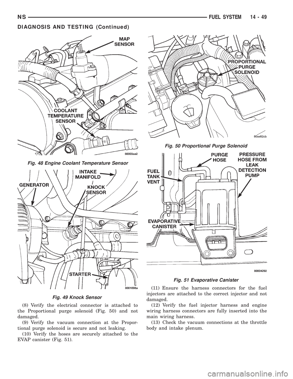
(8) Verify the electrical connector is attached to
the Proportional purge solenoid (Fig. 50) and not
damaged.
(9) Verify the vacuum connection at the Propor-
tional purge solenoid is secure and not leaking.
(10) Verify the hoses are securely attached to the
EVAP canister (Fig. 51).(11) Ensure the harness connectors for the fuel
injectors are attached to the correct injector and not
damaged.
(12) Verify the fuel injector harness and engine
wiring harness connectors are fully inserted into the
main wiring harness.
(13) Check the vacuum connections at the throttle
body and intake plenum.
Fig. 48 Engine Coolant Temperature Sensor
Fig. 49 Knock Sensor
Fig. 50 Proportional Purge Solenoid
Fig. 51 Evaporative Canister
NSFUEL SYSTEM 14 - 49
DIAGNOSIS AND TESTING (Continued)
Page 1344 of 1938
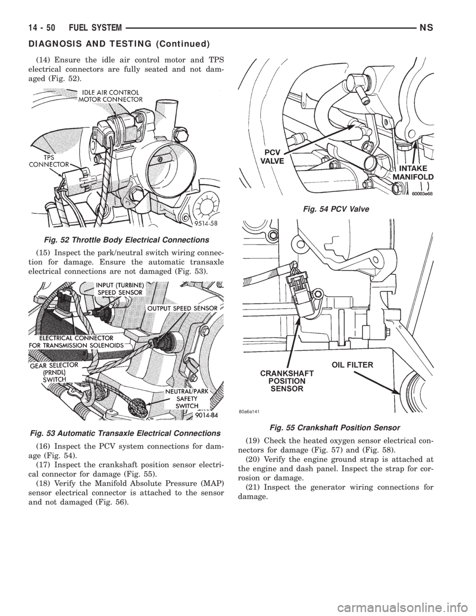
(14) Ensure the idle air control motor and TPS
electrical connectors are fully seated and not dam-
aged (Fig. 52).
(15) Inspect the park/neutral switch wiring connec-
tion for damage. Ensure the automatic transaxle
electrical connections are not damaged (Fig. 53).
(16) Inspect the PCV system connections for dam-
age (Fig. 54).
(17) Inspect the crankshaft position sensor electri-
cal connector for damage (Fig. 55).
(18) Verify the Manifold Absolute Pressure (MAP)
sensor electrical connector is attached to the sensor
and not damaged (Fig. 56).(19) Check the heated oxygen sensor electrical con-
nectors for damage (Fig. 57) and (Fig. 58).
(20) Verify the engine ground strap is attached at
the engine and dash panel. Inspect the strap for cor-
rosion or damage.
(21) Inspect the generator wiring connections for
damage.
Fig. 52 Throttle Body Electrical Connections
Fig. 53 Automatic Transaxle Electrical Connections
Fig. 54 PCV Valve
Fig. 55 Crankshaft Position Sensor
14 - 50 FUEL SYSTEMNS
DIAGNOSIS AND TESTING (Continued)
Page 1345 of 1938
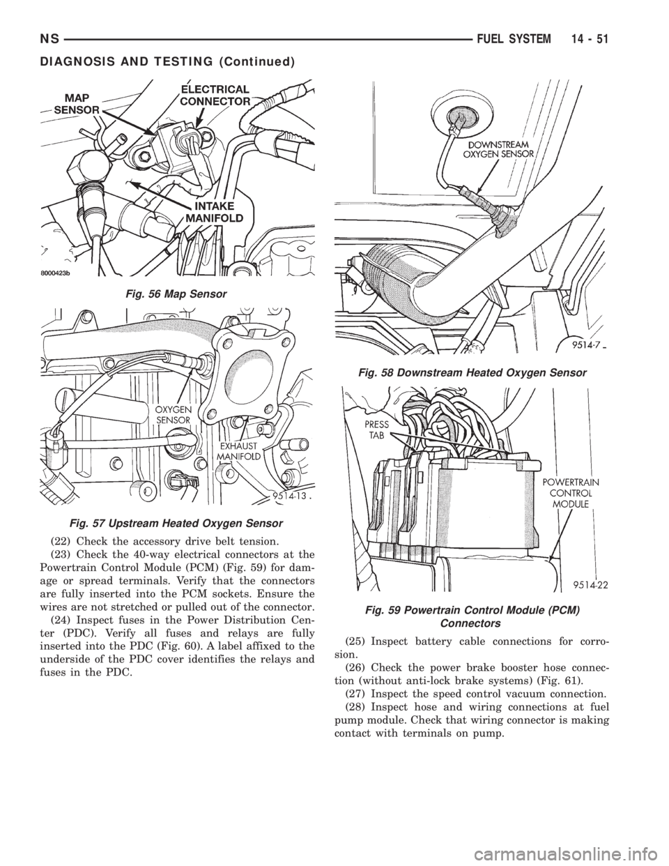
(22) Check the accessory drive belt tension.
(23) Check the 40-way electrical connectors at the
Powertrain Control Module (PCM) (Fig. 59) for dam-
age or spread terminals. Verify that the connectors
are fully inserted into the PCM sockets. Ensure the
wires are not stretched or pulled out of the connector.
(24) Inspect fuses in the Power Distribution Cen-
ter (PDC). Verify all fuses and relays are fully
inserted into the PDC (Fig. 60). A label affixed to the
underside of the PDC cover identifies the relays and
fuses in the PDC.(25) Inspect battery cable connections for corro-
sion.
(26) Check the power brake booster hose connec-
tion (without anti-lock brake systems) (Fig. 61).
(27) Inspect the speed control vacuum connection.
(28) Inspect hose and wiring connections at fuel
pump module. Check that wiring connector is making
contact with terminals on pump.
Fig. 56 Map Sensor
Fig. 57 Upstream Heated Oxygen Sensor
Fig. 58 Downstream Heated Oxygen Sensor
Fig. 59 Powertrain Control Module (PCM)
Connectors
NSFUEL SYSTEM 14 - 51
DIAGNOSIS AND TESTING (Continued)
Page 1347 of 1938
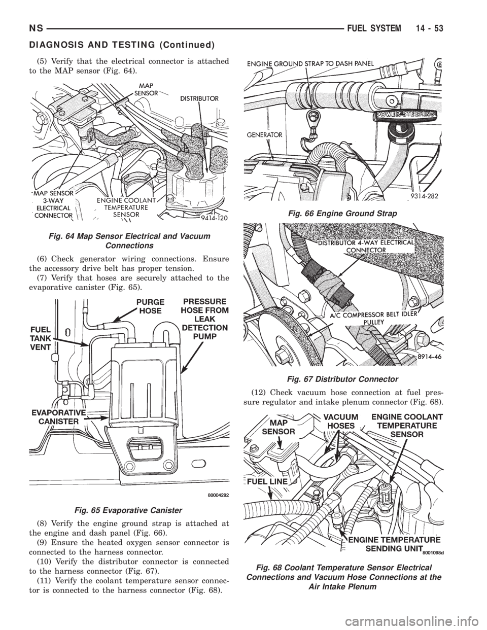
(5) Verify that the electrical connector is attached
to the MAP sensor (Fig. 64).
(6) Check generator wiring connections. Ensure
the accessory drive belt has proper tension.
(7) Verify that hoses are securely attached to the
evaporative canister (Fig. 65).
(8) Verify the engine ground strap is attached at
the engine and dash panel (Fig. 66).
(9) Ensure the heated oxygen sensor connector is
connected to the harness connector.
(10) Verify the distributor connector is connected
to the harness connector (Fig. 67).
(11) Verify the coolant temperature sensor connec-
tor is connected to the harness connector (Fig. 68).(12) Check vacuum hose connection at fuel pres-
sure regulator and intake plenum connector (Fig. 68).
Fig. 64 Map Sensor Electrical and Vacuum
Connections
Fig. 65 Evaporative Canister
Fig. 66 Engine Ground Strap
Fig. 67 Distributor Connector
Fig. 68 Coolant Temperature Sensor Electrical
Connections and Vacuum Hose Connections at the
Air Intake Plenum
NSFUEL SYSTEM 14 - 53
DIAGNOSIS AND TESTING (Continued)
Page 1349 of 1938
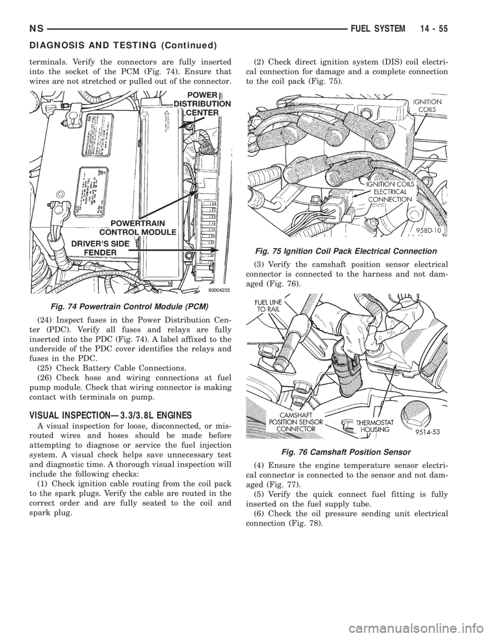
terminals. Verify the connectors are fully inserted
into the socket of the PCM (Fig. 74). Ensure that
wires are not stretched or pulled out of the connector.
(24) Inspect fuses in the Power Distribution Cen-
ter (PDC). Verify all fuses and relays are fully
inserted into the PDC (Fig. 74). A label affixed to the
underside of the PDC cover identifies the relays and
fuses in the PDC.
(25) Check Battery Cable Connections.
(26) Check hose and wiring connections at fuel
pump module. Check that wiring connector is making
contact with terminals on pump.
VISUAL INSPECTIONÐ3.3/3.8L ENGINES
A visual inspection for loose, disconnected, or mis-
routed wires and hoses should be made before
attempting to diagnose or service the fuel injection
system. A visual check helps save unnecessary test
and diagnostic time. A thorough visual inspection will
include the following checks:
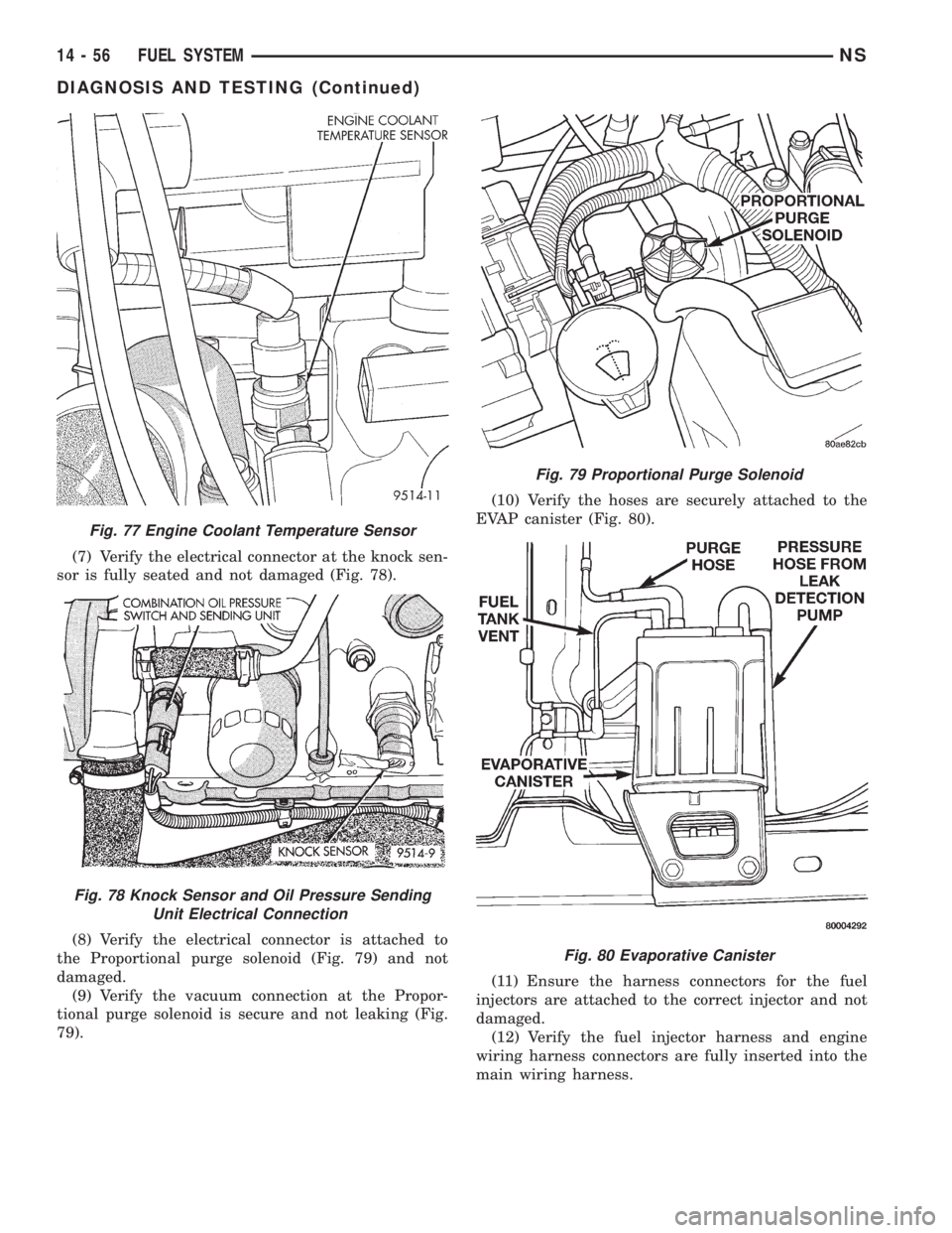
(1) Check ignition cable routing from the coil pack
to the spark plugs. Verify the cable are routed in the
correct order and are fully seated to the coil and
spark plug.(2) Check direct ignition system (DIS) coil electri-
cal connection for damage and a complete connection
to the coil pack (Fig. 75).
(3) Verify the camshaft position sensor electrical
connector is connected to the harness and not dam-
aged (Fig. 76).
(4) Ensure the engine temperature sensor electri-
cal connector is connected to the sensor and not dam-
aged (Fig. 77).
(5) Verify the quick connect fuel fitting is fully
inserted on the fuel supply tube.
(6) Check the oil pressure sending unit electrical
connection (Fig. 78).
Fig. 74 Powertrain Control Module (PCM)
Fig. 75 Ignition Coil Pack Electrical Connection
Fig. 76 Camshaft Position Sensor
NSFUEL SYSTEM 14 - 55
DIAGNOSIS AND TESTING (Continued)
Page 1350 of 1938
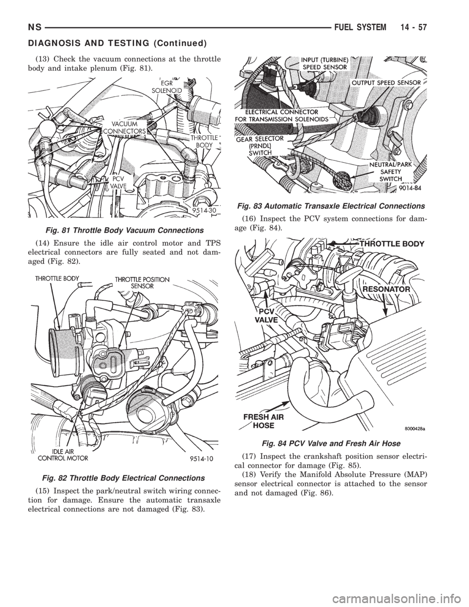
(7) Verify the electrical connector at the knock sen-
sor is fully seated and not damaged (Fig. 78).
(8) Verify the electrical connector is attached to
the Proportional purge solenoid (Fig. 79) and not
damaged.
(9) Verify the vacuum connection at the Propor-
tional purge solenoid is secure and not leaking (Fig.
79).(10) Verify the hoses are securely attached to the
EVAP canister (Fig. 80).
(11) Ensure the harness connectors for the fuel
injectors are attached to the correct injector and not
damaged.
(12) Verify the fuel injector harness and engine
wiring harness connectors are fully inserted into the
main wiring harness.
Fig. 77 Engine Coolant Temperature Sensor
Fig. 78 Knock Sensor and Oil Pressure Sending
Unit Electrical Connection
Fig. 79 Proportional Purge Solenoid
Fig. 80 Evaporative Canister
14 - 56 FUEL SYSTEMNS
DIAGNOSIS AND TESTING (Continued)
Page 1351 of 1938
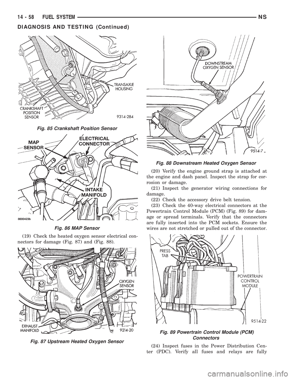
(13) Check the vacuum connections at the throttle
body and intake plenum (Fig. 81).
(14) Ensure the idle air control motor and TPS
electrical connectors are fully seated and not dam-
aged (Fig. 82).
(15) Inspect the park/neutral switch wiring connec-
tion for damage. Ensure the automatic transaxle
electrical connections are not damaged (Fig. 83).(16) Inspect the PCV system connections for dam-
age (Fig. 84).
(17) Inspect the crankshaft position sensor electri-
cal connector for damage (Fig. 85).
(18) Verify the Manifold Absolute Pressure (MAP)
sensor electrical connector is attached to the sensor
and not damaged (Fig. 86).
Fig. 81 Throttle Body Vacuum Connections
Fig. 82 Throttle Body Electrical Connections
Fig. 83 Automatic Transaxle Electrical Connections
Fig. 84 PCV Valve and Fresh Air Hose
NSFUEL SYSTEM 14 - 57
DIAGNOSIS AND TESTING (Continued)
Page 1352 of 1938
(19) Check the heated oxygen sensor electrical con-
nectors for damage (Fig. 87) and (Fig. 88).(20) Verify the engine ground strap is attached at
the engine and dash panel. Inspect the strap for cor-
rosion or damage.
(21) Inspect the generator wiring connections for
damage.
(22) Check the accessory drive belt tension.
(23) Check the 40-way electrical connectors at the
Powertrain Control Module (PCM) (Fig. 89) for dam-
age or spread terminals. Verify that the connectors
are fully inserted into the PCM sockets. Ensure the
wires are not stretched or pulled out of the connector.
(24) Inspect fuses in the Power Distribution Cen-
ter (PDC). Verify all fuses and relays are fully
Fig. 85 Crankshaft Position Sensor
Fig. 86 MAP Sensor
Fig. 87 Upstream Heated Oxygen Sensor
Fig. 88 Downstream Heated Oxygen Sensor
Fig. 89 Powertrain Control Module (PCM)
Connectors
14 - 58 FUEL SYSTEMNS
DIAGNOSIS AND TESTING (Continued)
Page 1354 of 1938
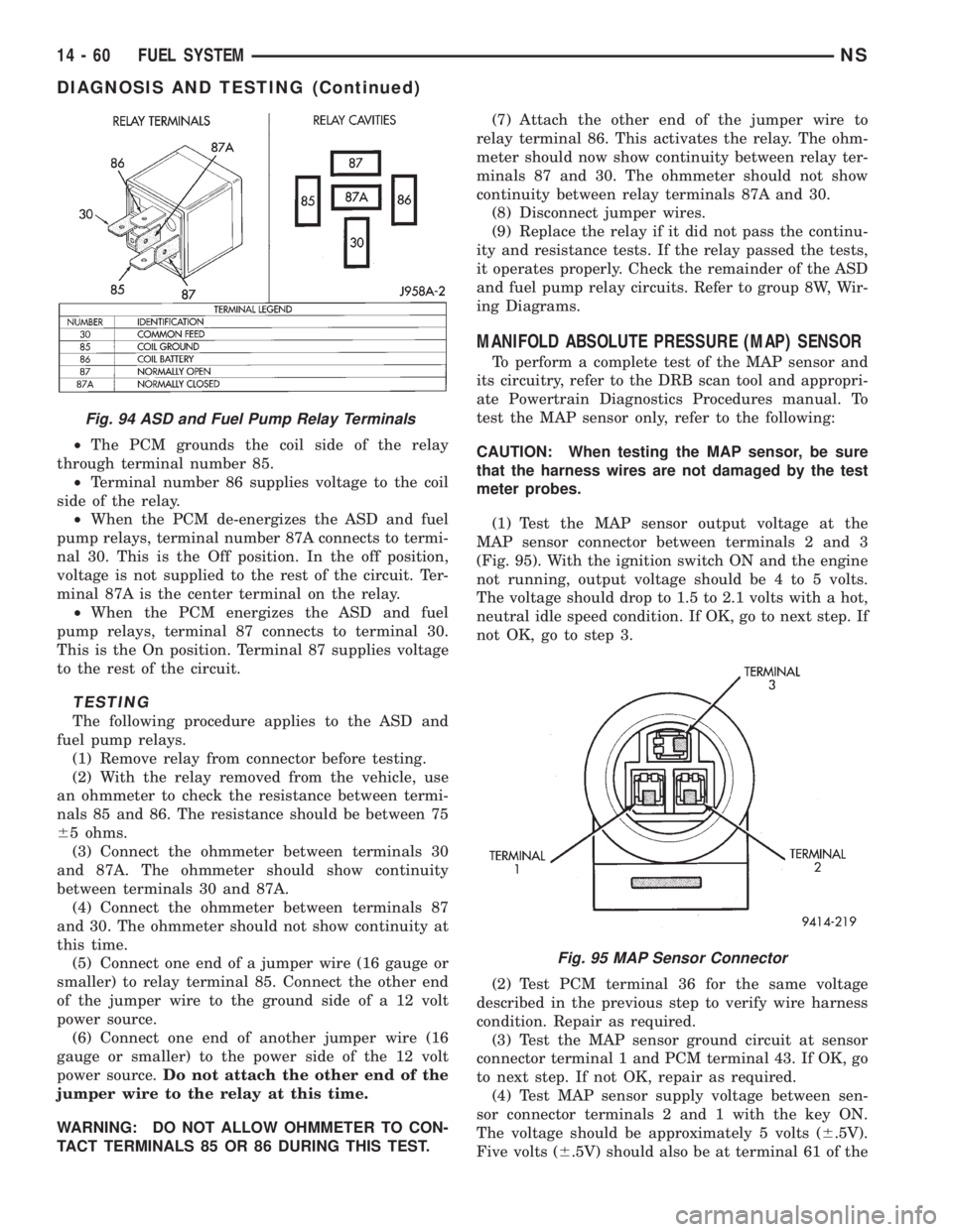
²The PCM grounds the coil side of the relay
through terminal number 85.
²Terminal number 86 supplies voltage to the coil
side of the relay.
²When the PCM de-energizes the ASD and fuel
pump relays, terminal number 87A connects to termi-
nal 30. This is the Off position. In the off position,
voltage is not supplied to the rest of the circuit. Ter-
minal 87A is the center terminal on the relay.
²When the PCM energizes the ASD and fuel
pump relays, terminal 87 connects to terminal 30.
This is the On position. Terminal 87 supplies voltage
to the rest of the circuit.
TESTING
The following procedure applies to the ASD and
fuel pump relays.
(1) Remove relay from connector before testing.
(2) With the relay removed from the vehicle, use
an ohmmeter to check the resistance between termi-
nals 85 and 86. The resistance should be between 75
65 ohms.
(3) Connect the ohmmeter between terminals 30
and 87A. The ohmmeter should show continuity
between terminals 30 and 87A.
(4) Connect the ohmmeter between terminals 87
and 30. The ohmmeter should not show continuity at
this time.
(5) Connect one end of a jumper wire (16 gauge or
smaller) to relay terminal 85. Connect the other end
of the jumper wire to the ground side of a 12 volt
power source.
(6) Connect one end of another jumper wire (16
gauge or smaller) to the power side of the 12 volt
power source.Do not attach the other end of the
jumper wire to the relay at this time.
WARNING: DO NOT ALLOW OHMMETER TO CON-
TACT TERMINALS 85 OR 86 DURING THIS TEST.(7) Attach the other end of the jumper wire to
relay terminal 86. This activates the relay. The ohm-
meter should now show continuity between relay ter-
minals 87 and 30. The ohmmeter should not show
continuity between relay terminals 87A and 30.
(8) Disconnect jumper wires.
(9) Replace the relay if it did not pass the continu-
ity and resistance tests. If the relay passed the tests,
it operates properly. Check the remainder of the ASD
and fuel pump relay circuits. Refer to group 8W, Wir-
ing Diagrams.
MANIFOLD ABSOLUTE PRESSURE (MAP) SENSOR
To perform a complete test of the MAP sensor and
its circuitry, refer to the DRB scan tool and appropri-
ate Powertrain Diagnostics Procedures manual. To
test the MAP sensor only, refer to the following:
CAUTION: When testing the MAP sensor, be sure
that the harness wires are not damaged by the test
meter probes.
(1) Test the MAP sensor output voltage at the
MAP sensor connector between terminals 2 and 3
(Fig. 95). With the ignition switch ON and the engine
not running, output voltage should be 4 to 5 volts.
The voltage should drop to 1.5 to 2.1 volts with a hot,
neutral idle speed condition. If OK, go to next step. If
not OK, go to step 3.
(2) Test PCM terminal 36 for the same voltage
described in the previous step to verify wire harness
condition. Repair as required.
(3) Test the MAP sensor ground circuit at sensor
connector terminal 1 and PCM terminal 43. If OK, go
to next step. If not OK, repair as required.
(4) Test MAP sensor supply voltage between sen-
sor connector terminals 2 and 1 with the key ON.
The voltage should be approximately 5 volts (6.5V).
Five volts (6.5V) should also be at terminal 61 of the
Fig. 94 ASD and Fuel Pump Relay Terminals
Fig. 95 MAP Sensor Connector
14 - 60 FUEL SYSTEMNS
DIAGNOSIS AND TESTING (Continued)
Page 1355 of 1938
PCM. If OK, replace MAP sensor. If not OK, repair or
replace the wire harness as required.
HEATED OXYGEN SENSOR
Use an ohmmeter to test the heating element of
the oxygen sensors. Disconnect the electrical connec-
tor from each oxygen sensor. The white wires in the
sensor connector are the power and ground circuits
for the heater. Connect the ohmmeter test leads to
terminals of the white wires in the heated oxygen
sensor connector. Replace the heated oxygen sensor if
the resistance is not between 4 and 7 ohms.
KNOCK SENSOR
The engine knock sensor is affected by a number of
factors. A few of these are: ignition timing, cylinder
pressure, fuel octane, etc. The knock sensor gener-
ates an AC voltage whose amplitude increases with
the increase of engine knock. The knock sensor can
be tested with a digital voltmeter. The RMS voltage
starts at about 20mVac (at about 700 rpm) and
increases to approximately 600 mVac (5000 rpm). If
the output falls outside of this range a DTC will be
set.
CAMSHAFT AND CRANKSHAFT POSITION SENSOR
Refer to Group 8D, Ignition for Diagnosis and Test-
ing of Camshaft and Crankshaft Sensors.
ENGINE COOLANT TEMPERATURE SENSOR
(1) With the key off, disconnect wire harness con-
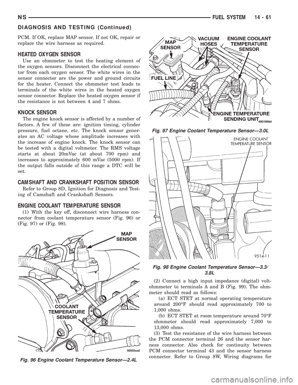
nector from coolant temperature sensor (Fig. 96) or
(Fig. 97) or (Fig. 98).
(2) Connect a high input impedance (digital) volt-
ohmmeter to terminals A and B (Fig. 99). The ohm-
meter should read as follows:
(a) ECT STET at normal operating temperature
around 200ÉF should read approximately 700 to
1,000 ohms.
(b) ECT STET at room temperature around 70ÉF
ohmmeter should read approximately 7,000 to
13,000 ohms.
(3) Test the resistance of the wire harness between
the PCM connector terminal 26 and the sensor har-
ness connector. Also check for continuity between
PCM connector terminal 43 and the sensor harness
connector. Refer to Group 8W, Wiring diagrams for
Fig. 96 Engine Coolant Temperature SensorÐ2.4L
Fig. 97 Engine Coolant Temperature SensorÐ3.0L
Fig. 98 Engine Coolant Temperature SensorÐ3.3/
3.8L
NSFUEL SYSTEM 14 - 61
DIAGNOSIS AND TESTING (Continued)