clock CHRYSLER VOYAGER 1996 Owner's Manual
[x] Cancel search | Manufacturer: CHRYSLER, Model Year: 1996, Model line: VOYAGER, Model: CHRYSLER VOYAGER 1996Pages: 1938, PDF Size: 55.84 MB
Page 405 of 1938

bracket behind the junction block/body control mod-
ule (Fig. 5).
REMOTE RADIO SWITCHES
A remote radio control switch option is available on
LXI models sold in North America with the AM/FM/
cassette/5-band graphic equalizer with CD changer
control feature (RBN sales code), or the AM/FM/CD/
cassette/3-band graphic equalizer (RAZ sales code)
radio receivers. Two rocker-type switches are
mounted on the back (instrument panel side) of the
steering wheel spokes. The switch on the left spoke is
the seek switch and has seek up, seek down, and pre-
set station advance functions. The switch on the
right spoke is the volume control switch and has vol-
ume up, and volume down functions (Fig. 6).
These switches are resistor multiplexed units that
are hard-wired to the Body Control Module (BCM)
through the clockspring. The BCM sends the propermessages on the Chrysler Collision Detection (CCD)
data bus network to the radio receiver. For diagnosis
of the BCM or the CCD data bus, the use of a DRB
scan tool and the proper Diagnostic Procedures man-
ual are recommended. For more information on the
operation of the remote radio switch controls, refer to
the owner's manual in the vehicle glove box.
NAME BRAND SPEAKER RELAY
Relay is located in the junction block. To test relay
refer to the Audio Diagnostic Test Procedures or use
a known good relay.
DIAGNOSIS AND TESTING
ANTENNA
WARNING: ON VEHICLES EQUIPPED WITH AIR-
BAGS, REFER TO GROUP 8M - PASSIVE
RESTRAINT SYSTEMS BEFORE ATTEMPTING ANY
STEERING WHEEL, STEERING COLUMN, OR
INSTRUMENT PANEL COMPONENT DIAGNOSIS OR
SERVICE. FAILURE TO TAKE THE PROPER PRE-
CAUTIONS COULD RESULT IN ACCIDENTAL AIR-
BAG DEPLOYMENT AND POSSIBLE PERSONAL
INJURY.
The following four tests are used to diagnose the
antenna with an ohmmeter:
²Test 1- Mast to ground test
²Test 2- Tip-of-mast to tip-of-conductor test
²Test 3- Body ground to battery ground test
²Test 4- Body ground to coaxial shield test.
The ohmmeter test lead connections for each test
are shown in Antenna Tests (Fig. 7).
NOTE: This model has a two-piece antenna coaxial
cable. Tests 2 and 4 must be conducted in two
steps to isolate a coaxial cable problem; from the
coaxial cable connection under the right end of the
instrument panel near the right cowl side panel to
the antenna base, and then from the coaxial cable
connection to the radio chassis connection.
TEST 1
Test 1 determines if the antenna mast is insulated
from the base. Proceed as follows:
(1) Unplug the antenna coaxial cable connector
from the radio chassis and isolate.
(2) Connect one ohmmeter test lead to the tip of
the antenna mast. Connect the other test lead to the
antenna base. Check for continuity.
(3) There should be no continuity. If continuity is
found, replace the faulty or damaged antenna base
and cable assembly.
Fig. 5 Choke Location
Fig. 6 Remote Radio Switch Operational View
NSAUDIO SYSTEMS 8F - 3
DESCRIPTION AND OPERATION (Continued)
Page 413 of 1938

HORNS
CONTENTS
page page
DESCRIPTION AND OPERATION
INTRODUCTION......................... 1
DIAGNOSIS AND TESTING
HORN RELAY........................... 1
HORN SYSTEM.......................... 3
HORN SYSTEM TEST..................... 3HORN................................. 1
HORNS SOUND CONTINUOUSLY............ 3
HORNS WILL NOT SOUND................ 2
REMOVAL AND INSTALLATION
HORN SWITCH.......................... 4
HORNS................................ 4
DESCRIPTION AND OPERATION
INTRODUCTION
WARNING: ON VEHICLES EQUIPPED WITH AIR-
BAG, SEE GROUP 8M, RESTRAINT SYSTEMS FOR
SAFETY PRECAUTIONS. DISCONNECT THE NEGA-
TIVE CABLE FROM THE BATTERY BEFORE SER-
VICING COMPONENTS INVOLVING THE AIRBAG
SYSTEM. ACCIDENTAL DEPLOYMENT OF AIRBAG
AND PERSONAL INJURY CAN RESULT.
The horn circuit consists of a horn switch, clock-
spring, horn relay, horns and Body Control Module
(Fig. 1). The horn switch is a membrane switch
located in the airbag cover. The horns are located for-
ward of the left front wheel behind the bumper fas-
cia. The horn relay plugs into the junction block. For
circuit information and component locations refer to
Group 8W, Wiring Diagrams.
DIAGNOSIS AND TESTING
HORN
(1) Disconnect wire connector at horn.
(2) Using a voltmeter, connect one lead to ground
terminal and the other lead to the positive wire ter-
minal (Fig. 3).
(3) Depress the horn switch, battery voltage
should be present.
(4) If no voltage, refer to Horn Will Not Sound. If
voltage is OK, go to step Step 5.
(5) Using ohmmeter, test ground wire for continu-
ity to ground.
(6) If no ground repair as necessary.
(7) If wires test OK and horn does not sound,
replace horn.
HORN RELAY
(1) Remove horn relay.
(2) Using ohmmeter, test between relay connector
terminals 85 to 86 for 70 to 75 ohms resistance (Fig.
2). If resistance not OK, replace relay.
(3) Test for continuity between ground and termi-
nal 85 of horn relay.
(a) When the horn switch is not depressed, no
continuity should be present.
(b) Continuity to ground when horn switch is
depressed.
(c) If continuity is not correct repair horn
switch or wiring as necessary, refer to Group 8W,
Wiring Diagrams Group 8M Restraint System for
Driver's Airbag Module removal procedures.
(4) Using voltmeter, test voltage at:
(a) Terminals 30 and 86 of the horn relay to
body ground.
(b) If NO voltage check fuse 7 of the BCM.
(c) If incorrect voltage repair as necessary. Refer
to Group 8W, Wiring Diagrams.
(5) Insert a jumper wire between terminal 30 and
87 of the power distribution center.
(a) If horn sounds replace relay.
Fig. 1 Horn System
NSHORNS 8G - 1
Page 415 of 1938

HORNS SOUND CONTINUOUSLY
CAUTION: Continuous sounding of horns may
cause relay to fail.
The horn switch (membrane) sometimes can be the
cause without the switch being depressing.
(1) Remove the horn relay from the junction block.
(2) Using a continuity tester, test continuity from
the X3 cavity of the horn relay to ground. Refer to
Group 8W, Wiring Diagrams for circuit information.
(a) If continuity is detected, proceed to step Step
3.
(b) If NO continuity, replace the horn relay.
(3) Remove the airbag/horn pad from the steering
wheel and disengage horn connector.
(4) Install horn relay into junction block.
(a) If horn does not sound, replace airbag cover/
horn pad.
(b) If horn sounds, repair grounded X3 circuit
from junction block to clockspring in steering in
steering column. Refer to Group 8W, Wiring Dia-
grams.
HORN SYSTEM
Refer to Horn System Test below. If the horn does
not sound, check horn fuse located in the Power Dis-
tribution Center. If the fuse is blown, replace with
the correct fuse. If the horn fail to sound and the
new fuse blows when depressing the horn switch, a
short circuit in the horn or the horn wiring between
the fuse terminal and the horn is responsible, or a
defective horn switch allowed the horn to burn out is
responsible.
If the fuse is OK, test horn relay refer to Horn
Relay Test.
If the relay is OK, test horn. Refer to Horn System
Test.
CAUTION: Continuous sounding of horn may
cause horn relay to fail.
Should the horn sound continuously:
²Unplug the horn relay from Power Distribution
Center.
²Refer to Horn Relay Test.
Refer to Group 8W, Wiring Diagrams for circuit
and wiring information.
HORN SYSTEM TEST
CONDITION POSSIBLE CAUSE CORRECTION
Horn sounds continuously.
NOTE: Immediately unplug horn
relay in the Power Distribution
Center (PDC)(1) Faulty horn relay.
(2) Horn control circuit to relay
shorted to ground.
(3) Pinched horn switch wire under
Driver Airbag Module.
(4) Defective horn switch(1) Refer to horn relay test.
(2) Check terminal 85 in Junction
Block for continuity to ground. If
continuity to ground indicates:
(a) Steering Wheel horn switch/lead
shorted to ground.
(b) Wiring harness shorted to
ground. Find the short and repair as
necessary.
(3) Replace Driver Airbag Module.
(4) Replace Driver Airbag Module.
Horn sound intermittently as the
steering wheel is turned.(1) Horn relay control circuit X3 is
shorted to ground inside steering
column or wheel.
(2) Pinched horn switch wire under
Driver Airbag Module
(3) Defective horn switch(1) Remove Driver Airbag Module
and/or wheel. Check for rubbing or
loose wire/connector, repair as
necessary.
(2) Replace Driver Airbag Module.
(3) Replace Driver Airbag Module.
Horn does not sound (1) Check fuse 6 in PDC
(2) No Voltage at horn relay
terminals 30 & 86, and fuse is OK.
(3) Open circuit from terminal 85 of
the horn relay to horn switch, X3
circuit.
(4) Defective or damaged horn.
(5) Defective horn switch(1) Replace fuse if blown repair as
necessary.
(2) No voltage, repair the A6 circuit
as necessary.
(3) Repair circuit as necessary.
(4) Voltage at horn when horn switch
is pressed, replace horn.
(5) Replace Driver Airbag Module.
NSHORNS 8G - 3
DIAGNOSIS AND TESTING (Continued)
Page 425 of 1938
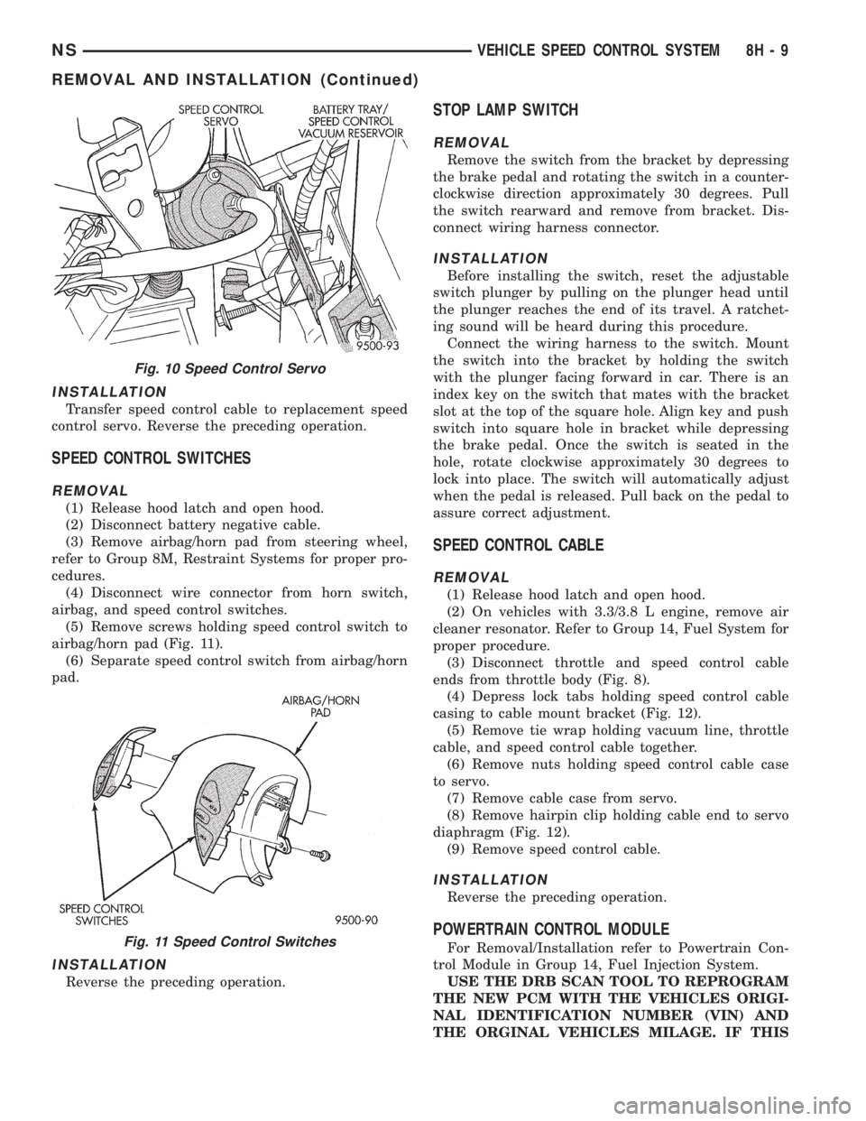
INSTALLATION
Transfer speed control cable to replacement speed
control servo. Reverse the preceding operation.
SPEED CONTROL SWITCHES
REMOVAL
(1) Release hood latch and open hood.
(2) Disconnect battery negative cable.
(3) Remove airbag/horn pad from steering wheel,
refer to Group 8M, Restraint Systems for proper pro-
cedures.
(4) Disconnect wire connector from horn switch,
airbag, and speed control switches.
(5) Remove screws holding speed control switch to
airbag/horn pad (Fig. 11).
(6) Separate speed control switch from airbag/horn
pad.
INSTALLATION
Reverse the preceding operation.
STOP LAMP SWITCH
REMOVAL
Remove the switch from the bracket by depressing
the brake pedal and rotating the switch in a counter-
clockwise direction approximately 30 degrees. Pull
the switch rearward and remove from bracket. Dis-
connect wiring harness connector.
INSTALLATION
Before installing the switch, reset the adjustable
switch plunger by pulling on the plunger head until
the plunger reaches the end of its travel. A ratchet-
ing sound will be heard during this procedure.
Connect the wiring harness to the switch. Mount
the switch into the bracket by holding the switch
with the plunger facing forward in car. There is an
index key on the switch that mates with the bracket
slot at the top of the square hole. Align key and push
switch into square hole in bracket while depressing
the brake pedal. Once the switch is seated in the
hole, rotate clockwise approximately 30 degrees to
lock into place. The switch will automatically adjust
when the pedal is released. Pull back on the pedal to
assure correct adjustment.
SPEED CONTROL CABLE
REMOVAL
(1) Release hood latch and open hood.
(2) On vehicles with 3.3/3.8 L engine, remove air
cleaner resonator. Refer to Group 14, Fuel System for
proper procedure.
(3) Disconnect throttle and speed control cable
ends from throttle body (Fig. 8).
(4) Depress lock tabs holding speed control cable
casing to cable mount bracket (Fig. 12).
(5) Remove tie wrap holding vacuum line, throttle
cable, and speed control cable together.
(6) Remove nuts holding speed control cable case
to servo.
(7) Remove cable case from servo.
(8) Remove hairpin clip holding cable end to servo
diaphragm (Fig. 12).
(9) Remove speed control cable.
INSTALLATION
Reverse the preceding operation.
POWERTRAIN CONTROL MODULE
For Removal/Installation refer to Powertrain Con-
trol Module in Group 14, Fuel Injection System.
USE THE DRB SCAN TOOL TO REPROGRAM
THE NEW PCM WITH THE VEHICLES ORIGI-
NAL IDENTIFICATION NUMBER (VIN) AND
THE ORGINAL VEHICLES MILAGE. IF THIS
Fig. 10 Speed Control Servo
Fig. 11 Speed Control Switches
NSVEHICLE SPEED CONTROL SYSTEM 8H - 9
REMOVAL AND INSTALLATION (Continued)
Page 429 of 1938

TURN SIGNAL AND FLASHERS
CONTENTS
page page
GENERAL INFORMATION
COMBINATION FLASHER.................. 1
INTRODUCTION......................... 1
DESCRIPTION AND OPERATION
COMBINATION FLASHER / DAYTIME
RUNNING LAMPS (DRL) MODULE......... 2
COMBINATION FLASHER FUNCTION......... 1DIAGNOSIS AND TESTING
COMBINATION FLASHER WITH / WITHOUT
DAYTIME RUNNING LAMPS MODULEÐ
CIRCUIT DIAGNOSTICS.................. 3
TURN SIGNAL MULTI-FUNCTION SWITCH.... 2
REMOVAL AND INSTALLATION
COMBINATION FLASHER WITH / WITHOUT
DRL MODULE........................ 11
MULTI-FUNCTION SWITCH............... 11
GENERAL INFORMATION
INTRODUCTION
The turn signals are actuated with a lever on the
left side of the steering column just ahead of the
steering wheel. The signals are automatically turned
off by a canceling cam (two lobes molded to the clock-
spring mechanism). The cam comes in contact with
the cancel actuator on the turn signal (multi-func-
tion) switch assembly. Either cam lobe, pushing on
the cancel actuator, returns the switch to the OFF
position.
Lane change signaling is actuated by applying par-
tial turn signal stalk movement toward the direction
desired until the indicator lamps flashes in the
instrument cluster. When the switch stalk is released
the stalk will spring back into the neutral position
turning OFF the turn signal.
With the ignition switch ON and the turn signal
switch stalk actuated left or right, current flows
through the:
²Combination flasher
²Multi-function switch
²Turn indicator lamp
²Front and rear turn signal bulbs.
A chime will sound after the vehicle has traveled a
distance of approximately 0.5 mile with the turn sig-
nal ON.
COMBINATION FLASHER
The Turn Signal/Hazard Warning Flasher is a
module providing the vehicle with turn signal and
hazard warning functions and has been designed
with internal relays to take advantage of low current
switching requirements in the vehicle. It is plugged
into the Junction Block at position 4 (Fig. 1), where
all wiring associated with its operation is terminated.The Junction Block is adjacent to and left of the
steering column of the vehicle.
To gain access to the flasher, remove the lower
steering column cover and knee blocker. Refer to
Group 8E, Instrument Panel and Systems for
removal procedures.
DESCRIPTION AND OPERATION
COMBINATION FLASHER FUNCTION
The Turn Signal/Hazard Warning Flasher is a
module providing turn signal, hazard warning func-
tions and has been designed with internal relays to
Fig. 1 Combination Flasher Location
NSTURN SIGNAL AND FLASHERS 8J - 1
Page 461 of 1938
EXTERIOR LAMP BULB SERVICE
INDEX
page page
REMOVAL AND INSTALLATION
CENTER HIGH MOUNTED STOP LAMP
(CHMSL) BULB........................ 13
FOG LAMP BULB ± TOWN and COUNTRY..... 11
FOG LAMP BULB........................ 10
FRONT PARKING AND TURN SIGNAL LAMP
BULB ± TOWN and COUNTRY............ 12
FRONT SIDE MARKER LAMP BULB TOWN and
COUNTRY............................ 11HEADLAMP BULB ± TOWN & COUNTRY....... 9
HEADLAMP BULB........................ 9
LICENSE PLATE LAMP BULB.............. 13
PARKING AND TURN SIGNAL BULB......... 11
TAIL, STOP, TURN SIGNAL AND BACK-UP
LAMP BULB.......................... 12
REMOVAL AND INSTALLATION
HEADLAMP BULB
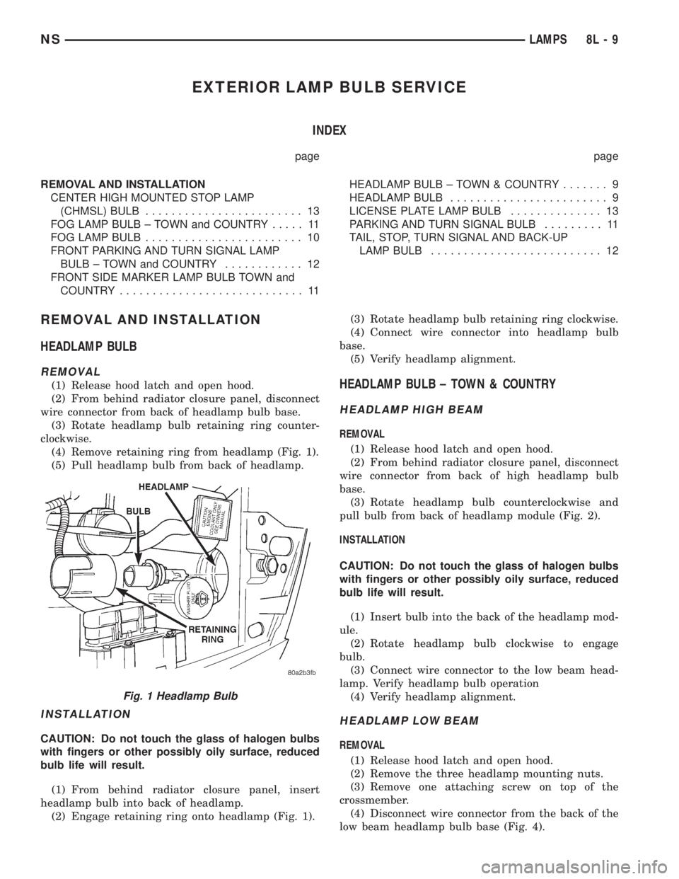
REMOVAL
(1) Release hood latch and open hood.
(2) From behind radiator closure panel, disconnect
wire connector from back of headlamp bulb base.
(3) Rotate headlamp bulb retaining ring counter-
clockwise.
(4) Remove retaining ring from headlamp (Fig. 1).
(5) Pull headlamp bulb from back of headlamp.
INSTALLATION
CAUTION: Do not touch the glass of halogen bulbs
with fingers or other possibly oily surface, reduced
bulb life will result.
(1) From behind radiator closure panel, insert
headlamp bulb into back of headlamp.
(2) Engage retaining ring onto headlamp (Fig. 1).(3) Rotate headlamp bulb retaining ring clockwise.
(4) Connect wire connector into headlamp bulb
base.
(5) Verify headlamp alignment.
HEADLAMP BULB ± TOWN & COUNTRY
HEADLAMP HIGH BEAM
REMOVAL
(1) Release hood latch and open hood.
(2) From behind radiator closure panel, disconnect
wire connector from back of high headlamp bulb
base.
(3) Rotate headlamp bulb counterclockwise and
pull bulb from back of headlamp module (Fig. 2).
INSTALLATION
CAUTION: Do not touch the glass of halogen bulbs
with fingers or other possibly oily surface, reduced
bulb life will result.
(1) Insert bulb into the back of the headlamp mod-
ule.
(2) Rotate headlamp bulb clockwise to engage
bulb.
(3) Connect wire connector to the low beam head-
lamp. Verify headlamp bulb operation
(4) Verify headlamp alignment.
HEADLAMP LOW BEAM
REMOVAL
(1) Release hood latch and open hood.
(2) Remove the three headlamp mounting nuts.
(3) Remove one attaching screw on top of the
crossmember.
(4) Disconnect wire connector from the back of the
low beam headlamp bulb base (Fig. 4).
Fig. 1 Headlamp Bulb
NSLAMPS 8L - 9
Page 462 of 1938
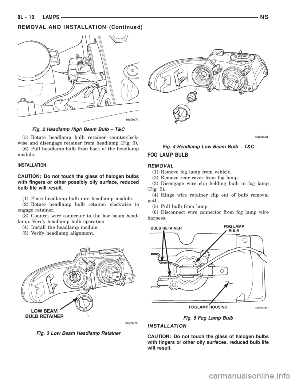
(5) Rotate headlamp bulb retainer counterclock-
wise and disengage retainer from headlamp (Fig. 3).
(6) Pull headlamp bulb from back of the headlamp
module.
INSTALLATION
CAUTION: Do not touch the glass of halogen bulbs
with fingers or other possibly oily surface, reduced
bulb life will result.
(1) Place headlamp bulb into headlamp module.
(2) Rotate headlamp bulb retainer clockwise to
engage retainer.
(3) Connect wire connector to the low beam head-
lamp. Verify headlamp bulb operation
(4) Install the headlamp module.
(5) Verify headlamp alignment.
FOG LAMP BULB
REMOVAL
(1) Remove fog lamp from vehicle.
(2) Remove rear cover from fog lamp.
(3) Disengage wire clip holding bulb in fog lamp
(Fig. 5).
(4) Hinge wire retainer clip out of bulb removal
path.
(5) Pull bulb from lamp.
(6) Disconnect wire connector from fog lamp wire
harness.
INSTALLATION
CAUTION: Do not touch the glass of halogen bulbs
with fingers or other oily surfaces, reduced bulb life
will result.
Fig. 2 Headlamp High Beam Bulb ± T&C
Fig. 3 Low Beam Headlamp Retainer
Fig. 4 Headlamp Low Beam Bulb ± T&C
Fig. 5 Fog Lamp Bulb
8L - 10 LAMPSNS
REMOVAL AND INSTALLATION (Continued)
Page 463 of 1938
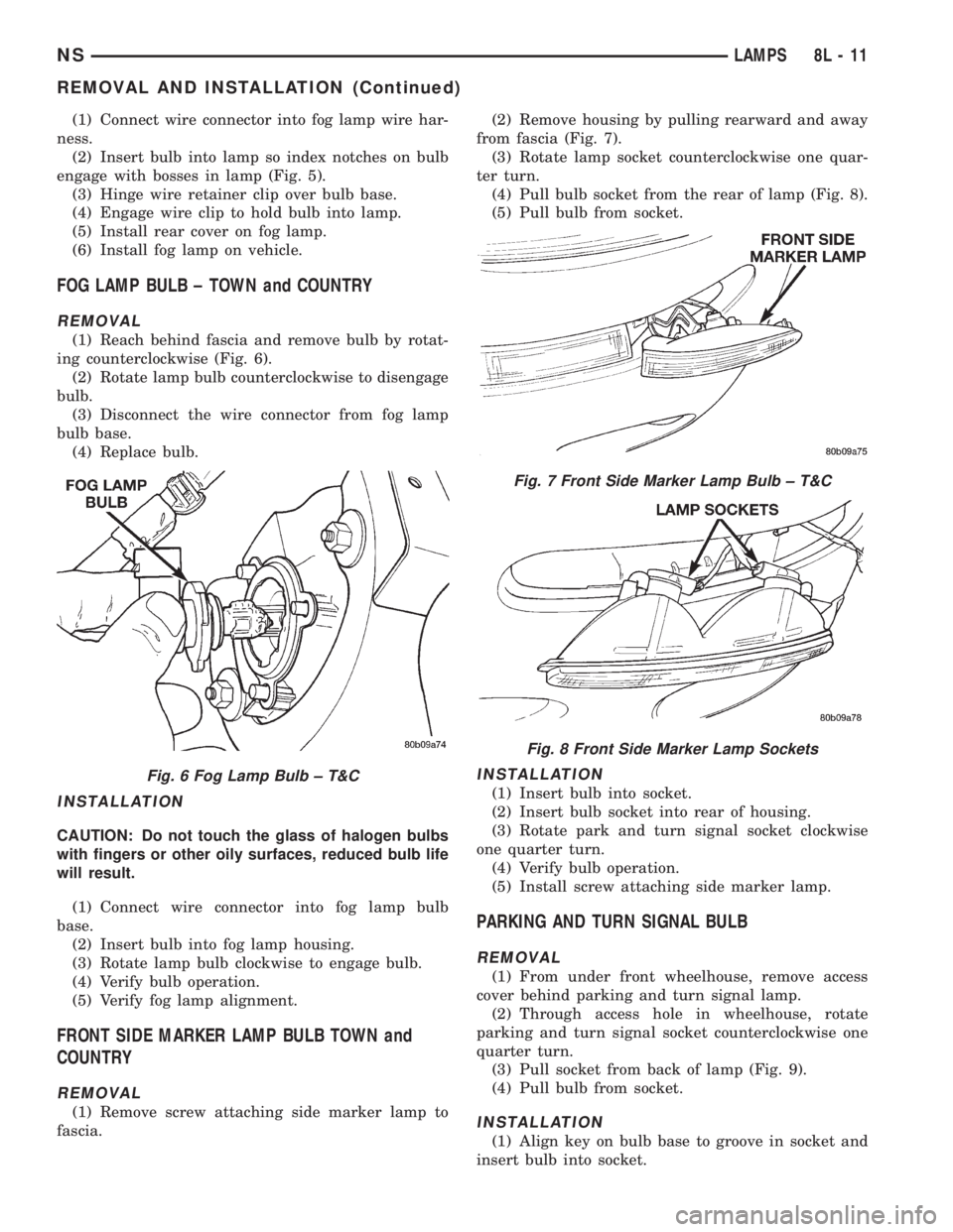
(1) Connect wire connector into fog lamp wire har-
ness.
(2) Insert bulb into lamp so index notches on bulb
engage with bosses in lamp (Fig. 5).
(3) Hinge wire retainer clip over bulb base.
(4) Engage wire clip to hold bulb into lamp.
(5) Install rear cover on fog lamp.
(6) Install fog lamp on vehicle.
FOG LAMP BULB ± TOWN and COUNTRY
REMOVAL
(1) Reach behind fascia and remove bulb by rotat-
ing counterclockwise (Fig. 6).
(2) Rotate lamp bulb counterclockwise to disengage
bulb.
(3) Disconnect the wire connector from fog lamp
bulb base.
(4) Replace bulb.
INSTALLATION
CAUTION: Do not touch the glass of halogen bulbs
with fingers or other oily surfaces, reduced bulb life
will result.
(1) Connect wire connector into fog lamp bulb
base.
(2) Insert bulb into fog lamp housing.
(3) Rotate lamp bulb clockwise to engage bulb.
(4) Verify bulb operation.
(5) Verify fog lamp alignment.
FRONT SIDE MARKER LAMP BULB TOWN and
COUNTRY
REMOVAL
(1) Remove screw attaching side marker lamp to
fascia.(2) Remove housing by pulling rearward and away
from fascia (Fig. 7).
(3) Rotate lamp socket counterclockwise one quar-
ter turn.
(4) Pull bulb socket from the rear of lamp (Fig. 8).
(5) Pull bulb from socket.
INSTALLATION
(1) Insert bulb into socket.
(2) Insert bulb socket into rear of housing.
(3) Rotate park and turn signal socket clockwise
one quarter turn.
(4) Verify bulb operation.
(5) Install screw attaching side marker lamp.
PARKING AND TURN SIGNAL BULB
REMOVAL
(1) From under front wheelhouse, remove access
cover behind parking and turn signal lamp.
(2) Through access hole in wheelhouse, rotate
parking and turn signal socket counterclockwise one
quarter turn.
(3) Pull socket from back of lamp (Fig. 9).
(4) Pull bulb from socket.
INSTALLATION
(1) Align key on bulb base to groove in socket and
insert bulb into socket.
Fig. 6 Fog Lamp Bulb ± T&C
Fig. 7 Front Side Marker Lamp Bulb ± T&C
Fig. 8 Front Side Marker Lamp Sockets
NSLAMPS 8L - 11
REMOVAL AND INSTALLATION (Continued)
Page 464 of 1938
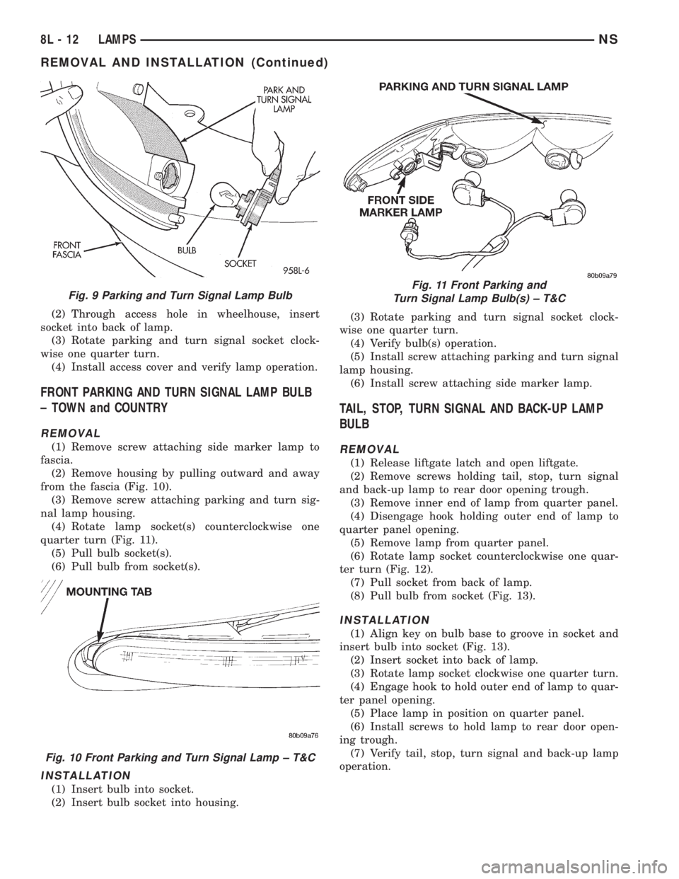
(2) Through access hole in wheelhouse, insert
socket into back of lamp.
(3) Rotate parking and turn signal socket clock-
wise one quarter turn.
(4) Install access cover and verify lamp operation.
FRONT PARKING AND TURN SIGNAL LAMP BULB
± TOWN and COUNTRY
REMOVAL
(1) Remove screw attaching side marker lamp to
fascia.
(2) Remove housing by pulling outward and away
from the fascia (Fig. 10).
(3) Remove screw attaching parking and turn sig-
nal lamp housing.
(4) Rotate lamp socket(s) counterclockwise one
quarter turn (Fig. 11).
(5) Pull bulb socket(s).
(6) Pull bulb from socket(s).
INSTALLATION
(1) Insert bulb into socket.
(2) Insert bulb socket into housing.(3) Rotate parking and turn signal socket clock-
wise one quarter turn.
(4) Verify bulb(s) operation.
(5) Install screw attaching parking and turn signal
lamp housing.
(6) Install screw attaching side marker lamp.
TAIL, STOP, TURN SIGNAL AND BACK-UP LAMP
BULB
REMOVAL
(1) Release liftgate latch and open liftgate.
(2) Remove screws holding tail, stop, turn signal
and back-up lamp to rear door opening trough.
(3) Remove inner end of lamp from quarter panel.
(4) Disengage hook holding outer end of lamp to
quarter panel opening.
(5) Remove lamp from quarter panel.
(6) Rotate lamp socket counterclockwise one quar-
ter turn (Fig. 12).
(7) Pull socket from back of lamp.
(8) Pull bulb from socket (Fig. 13).
INSTALLATION
(1) Align key on bulb base to groove in socket and
insert bulb into socket (Fig. 13).
(2) Insert socket into back of lamp.
(3) Rotate lamp socket clockwise one quarter turn.
(4) Engage hook to hold outer end of lamp to quar-
ter panel opening.
(5) Place lamp in position on quarter panel.
(6) Install screws to hold lamp to rear door open-
ing trough.
(7) Verify tail, stop, turn signal and back-up lamp
operation.
Fig. 9 Parking and Turn Signal Lamp Bulb
Fig. 10 Front Parking and Turn Signal Lamp ± T&C
Fig. 11 Front Parking and
Turn Signal Lamp Bulb(s) ± T&C
8L - 12 LAMPSNS
REMOVAL AND INSTALLATION (Continued)
Page 465 of 1938
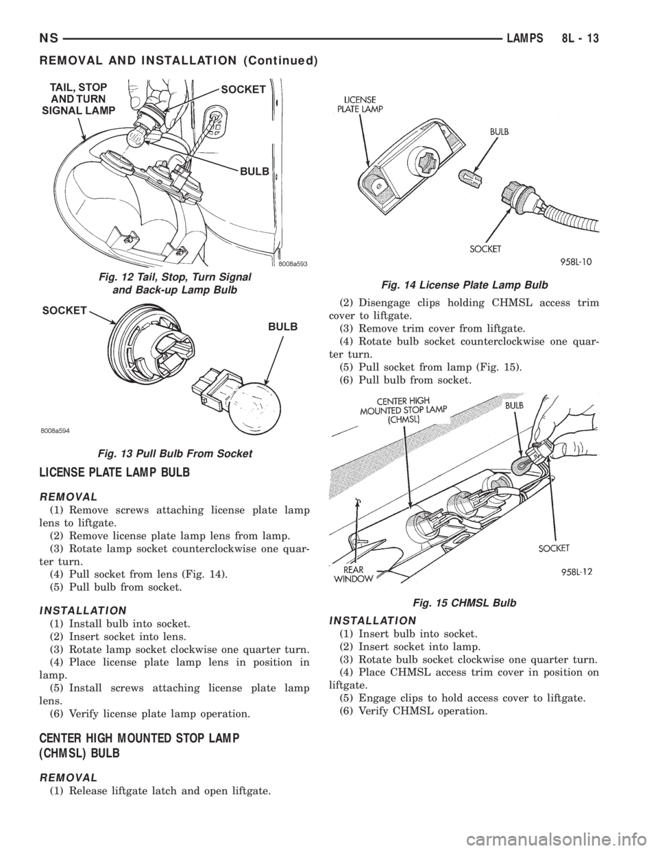
LICENSE PLATE LAMP BULB
REMOVAL
(1) Remove screws attaching license plate lamp
lens to liftgate.
(2) Remove license plate lamp lens from lamp.
(3) Rotate lamp socket counterclockwise one quar-
ter turn.
(4) Pull socket from lens (Fig. 14).
(5) Pull bulb from socket.
INSTALLATION
(1) Install bulb into socket.
(2) Insert socket into lens.
(3) Rotate lamp socket clockwise one quarter turn.
(4) Place license plate lamp lens in position in
lamp.
(5) Install screws attaching license plate lamp
lens.
(6) Verify license plate lamp operation.
CENTER HIGH MOUNTED STOP LAMP
(CHMSL) BULB
REMOVAL
(1) Release liftgate latch and open liftgate.(2) Disengage clips holding CHMSL access trim
cover to liftgate.
(3) Remove trim cover from liftgate.
(4) Rotate bulb socket counterclockwise one quar-
ter turn.
(5) Pull socket from lamp (Fig. 15).
(6) Pull bulb from socket.
INSTALLATION
(1) Insert bulb into socket.
(2) Insert socket into lamp.
(3) Rotate bulb socket clockwise one quarter turn.
(4) Place CHMSL access trim cover in position on
liftgate.
(5) Engage clips to hold access cover to liftgate.
(6) Verify CHMSL operation.
Fig. 12 Tail, Stop, Turn Signal
and Back-up Lamp Bulb
Fig. 13 Pull Bulb From Socket
Fig. 14 License Plate Lamp Bulb
Fig. 15 CHMSL Bulb
NSLAMPS 8L - 13
REMOVAL AND INSTALLATION (Continued)