clock CHRYSLER VOYAGER 1996 User Guide
[x] Cancel search | Manufacturer: CHRYSLER, Model Year: 1996, Model line: VOYAGER, Model: CHRYSLER VOYAGER 1996Pages: 1938, PDF Size: 55.84 MB
Page 250 of 1938
INSTALLATION
(1) Install fan module on radiator.
(2) Install radiator.
(3) Tighten receiver/dryer lower bolt.
(4) Install radiator attaching bolts.
(5) Install lower and upper radiator hoses.
(6) Connect fan module.
(7) Install air cleaner housing and intake hose.
(8) Install radiator closure panel crossmember.
(9) Install power steering reservoir attaching bolts.
(10) Refill cooling system. Refer to Refilling cooling
system in this section for procedure.
(11) Connect battery.
WATER PUMP BELT Ð 2.5L VM DIESEL
REMOVAL
(1) Remove generator/power steering belt. Refer to
procedure in this section.
(2) Raise vehicle on hoist.
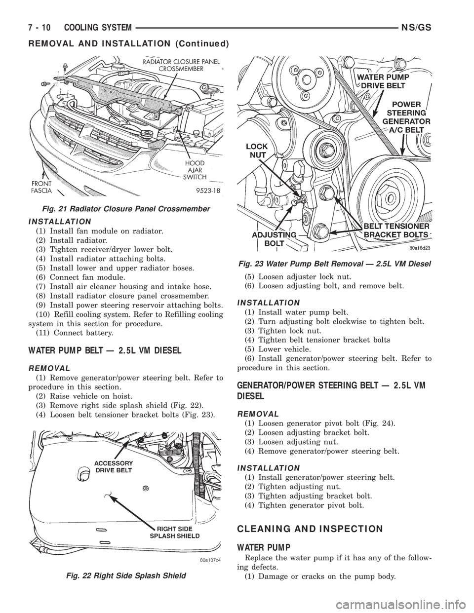
(3) Remove right side splash shield (Fig. 22).
(4) Loosen belt tensioner bracket bolts (Fig. 23).(5) Loosen adjuster lock nut.
(6) Loosen adjusting bolt, and remove belt.
INSTALLATION
(1) Install water pump belt.
(2) Turn adjusting bolt clockwise to tighten belt.
(3) Tighten lock nut.
(4) Tighten belt tensioner bracket bolts
(5) Lower vehicle.
(6) Install generator/power steering belt. Refer to
procedure in this section.
GENERATOR/POWER STEERING BELT Ð 2.5L VM
DIESEL
REMOVAL
(1) Loosen generator pivot bolt (Fig. 24).
(2) Loosen adjusting bracket bolt.
(3) Loosen adjusting nut.
(4) Remove generator/power steering belt.
INSTALLATION
(1) Install generator/power steering belt.
(2) Tighten adjusting nut.
(3) Tighten adjusting bracket bolt.
(4) Tighten generator pivot bolt.
CLEANING AND INSPECTION
WATER PUMP
Replace the water pump if it has any of the follow-
ing defects.
(1) Damage or cracks on the pump body.
Fig. 21 Radiator Closure Panel Crossmember
Fig. 22 Right Side Splash Shield
Fig. 23 Water Pump Belt Removal Ð 2.5L VM Diesel
7 - 10 COOLING SYSTEMNS/GS
REMOVAL AND INSTALLATION (Continued)
Page 357 of 1938
HEADLAMP SWITCH LAMP(S)
REMOVAL
(1) Remove instrument cluster bezel.
(2) Disconnect wire connectors.
(3) Remove headlamp switch bezel from instru-
ment cluster bezel.
(4) Rotate bulb socket counterclockwise one quar-
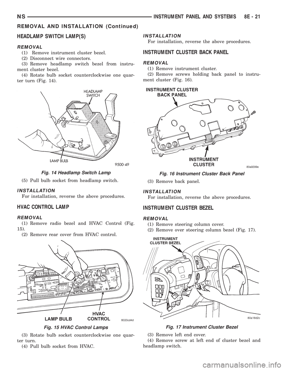
ter turn (Fig. 14).
(5) Pull bulb socket from headlamp switch.
INSTALLATION
For installation, reverse the above procedures.
HVAC CONTROL LAMP
REMOVAL
(1) Remove radio bezel and HVAC Control (Fig.
15).
(2) Remove rear cover from HVAC control.
(3) Rotate bulb socket counterclockwise one quar-
ter turn.
(4) Pull bulb socket from HVAC.
INSTALLATION
For installation, reverse the above procedures.
INSTRUMENT CLUSTER BACK PANEL
REMOVAL
(1) Remove instrument cluster.
(2) Remove screws holding back panel to instru-
ment cluster (Fig. 16).
(3) Remove back panel.
INSTALLATION
For installation, reverse the above procedures.
INSTRUMENT CLUSTER BEZEL
REMOVAL
(1) Remove steering column cover.
(2) Remove over steering column bezel (Fig. 17).
(3) Remove left end cover.
(4) Remove screw at left end of cluster bezel and
headlamp switch.
Fig. 14 Headlamp Switch Lamp
Fig. 15 HVAC Control Lamps
Fig. 16 Instrument Cluster Back Panel
Fig. 17 Instrument Cluster Bezel
NSINSTRUMENT PANEL AND SYSTEMS 8E - 21
REMOVAL AND INSTALLATION (Continued)
Page 368 of 1938
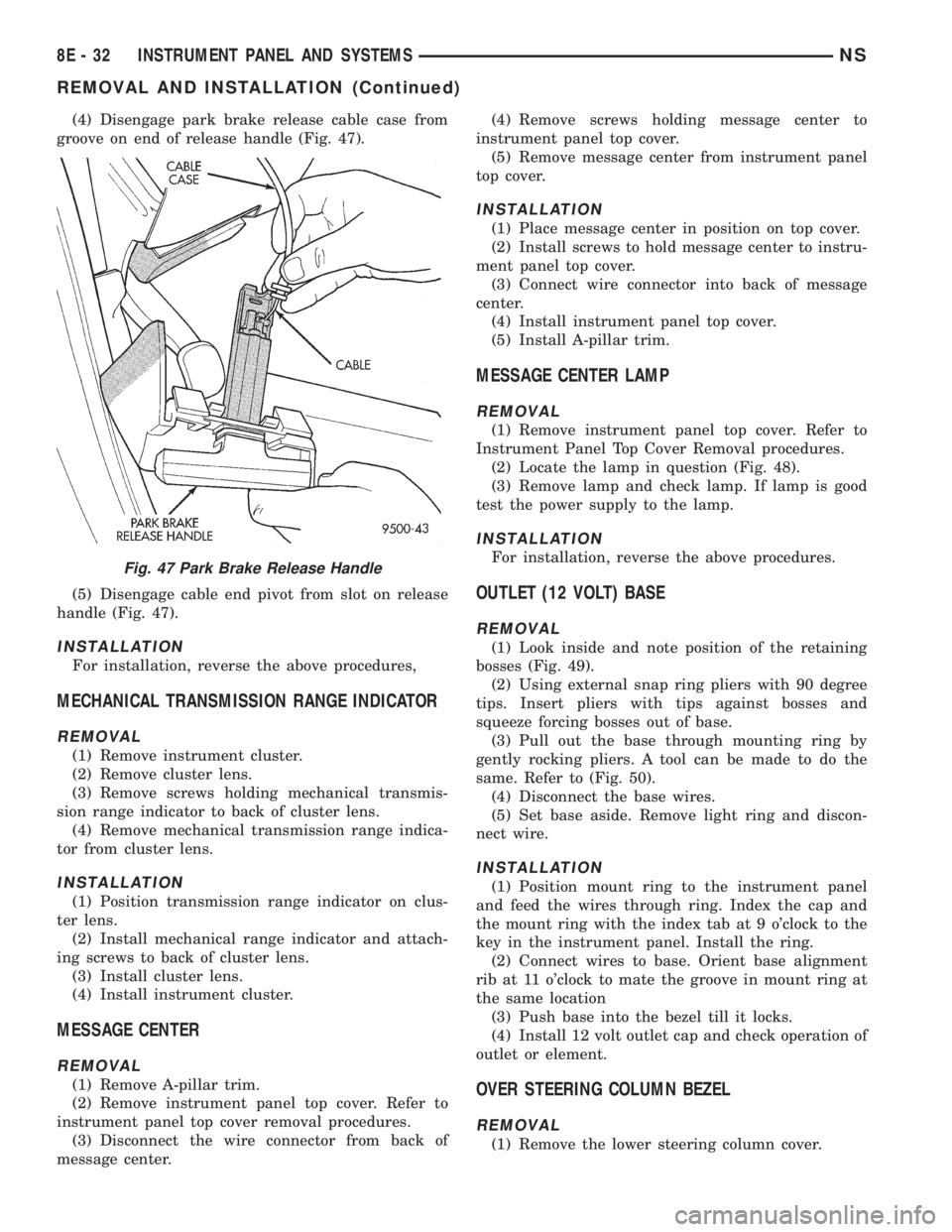
(4) Disengage park brake release cable case from
groove on end of release handle (Fig. 47).
(5) Disengage cable end pivot from slot on release
handle (Fig. 47).
INSTALLATION
For installation, reverse the above procedures,
MECHANICAL TRANSMISSION RANGE INDICATOR
REMOVAL
(1) Remove instrument cluster.
(2) Remove cluster lens.
(3) Remove screws holding mechanical transmis-
sion range indicator to back of cluster lens.
(4) Remove mechanical transmission range indica-
tor from cluster lens.
INSTALLATION
(1) Position transmission range indicator on clus-
ter lens.
(2) Install mechanical range indicator and attach-
ing screws to back of cluster lens.
(3) Install cluster lens.
(4) Install instrument cluster.
MESSAGE CENTER
REMOVAL
(1) Remove A-pillar trim.
(2) Remove instrument panel top cover. Refer to
instrument panel top cover removal procedures.
(3) Disconnect the wire connector from back of
message center.(4) Remove screws holding message center to
instrument panel top cover.
(5) Remove message center from instrument panel
top cover.
INSTALLATION
(1) Place message center in position on top cover.
(2) Install screws to hold message center to instru-
ment panel top cover.
(3) Connect wire connector into back of message
center.
(4) Install instrument panel top cover.
(5) Install A-pillar trim.
MESSAGE CENTER LAMP
REMOVAL
(1) Remove instrument panel top cover. Refer to
Instrument Panel Top Cover Removal procedures.
(2) Locate the lamp in question (Fig. 48).
(3) Remove lamp and check lamp. If lamp is good
test the power supply to the lamp.
INSTALLATION
For installation, reverse the above procedures.
OUTLET (12 VOLT) BASE
REMOVAL
(1) Look inside and note position of the retaining
bosses (Fig. 49).
(2) Using external snap ring pliers with 90 degree
tips. Insert pliers with tips against bosses and
squeeze forcing bosses out of base.
(3) Pull out the base through mounting ring by
gently rocking pliers. A tool can be made to do the
same. Refer to (Fig. 50).
(4) Disconnect the base wires.
(5) Set base aside. Remove light ring and discon-
nect wire.
INSTALLATION
(1) Position mount ring to the instrument panel
and feed the wires through ring. Index the cap and
the mount ring with the index tab at 9 o'clock to the
key in the instrument panel. Install the ring.
(2) Connect wires to base. Orient base alignment
rib at 11 o'clock to mate the groove in mount ring at
the same location
(3) Push base into the bezel till it locks.
(4) Install 12 volt outlet cap and check operation of
outlet or element.
OVER STEERING COLUMN BEZEL
REMOVAL
(1) Remove the lower steering column cover.
Fig. 47 Park Brake Release Handle
8E - 32 INSTRUMENT PANEL AND SYSTEMSNS
REMOVAL AND INSTALLATION (Continued)
Page 370 of 1938
with traction control switch connect the wire pigtail
before engaging clips.
(2) Install the screws to hold the over steering col-
umn bezel to the cluster bezel.
(3) Install the lower column cover.
POWER MIRROR SWITCH
REMOVAL
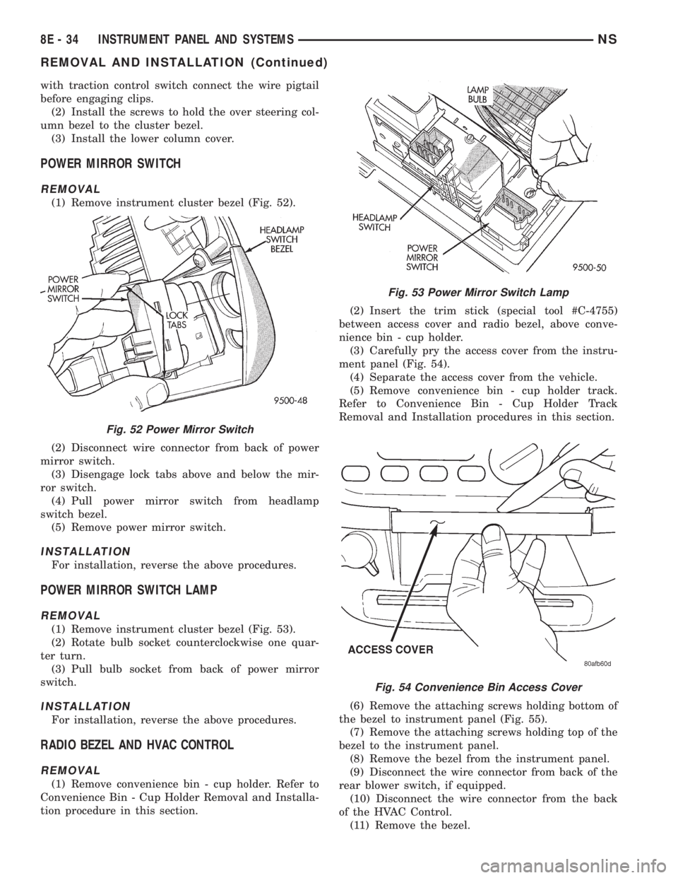
(1) Remove instrument cluster bezel (Fig. 52).
(2) Disconnect wire connector from back of power
mirror switch.
(3) Disengage lock tabs above and below the mir-
ror switch.
(4) Pull power mirror switch from headlamp
switch bezel.
(5) Remove power mirror switch.
INSTALLATION
For installation, reverse the above procedures.
POWER MIRROR SWITCH LAMP
REMOVAL
(1) Remove instrument cluster bezel (Fig. 53).
(2) Rotate bulb socket counterclockwise one quar-
ter turn.
(3) Pull bulb socket from back of power mirror
switch.
INSTALLATION
For installation, reverse the above procedures.
RADIO BEZEL AND HVAC CONTROL
REMOVAL
(1) Remove convenience bin - cup holder. Refer to
Convenience Bin - Cup Holder Removal and Installa-
tion procedure in this section.(2) Insert the trim stick (special tool #C-4755)
between access cover and radio bezel, above conve-
nience bin - cup holder.
(3) Carefully pry the access cover from the instru-
ment panel (Fig. 54).
(4) Separate the access cover from the vehicle.
(5) Remove convenience bin - cup holder track.
Refer to Convenience Bin - Cup Holder Track
Removal and Installation procedures in this section.
(6) Remove the attaching screws holding bottom of
the bezel to instrument panel (Fig. 55).
(7) Remove the attaching screws holding top of the
bezel to the instrument panel.
(8) Remove the bezel from the instrument panel.
(9) Disconnect the wire connector from back of the
rear blower switch, if equipped.
(10) Disconnect the wire connector from the back
of the HVAC Control.
(11) Remove the bezel.
Fig. 52 Power Mirror Switch
Fig. 53 Power Mirror Switch Lamp
Fig. 54 Convenience Bin Access Cover
8E - 34 INSTRUMENT PANEL AND SYSTEMSNS
REMOVAL AND INSTALLATION (Continued)
Page 371 of 1938
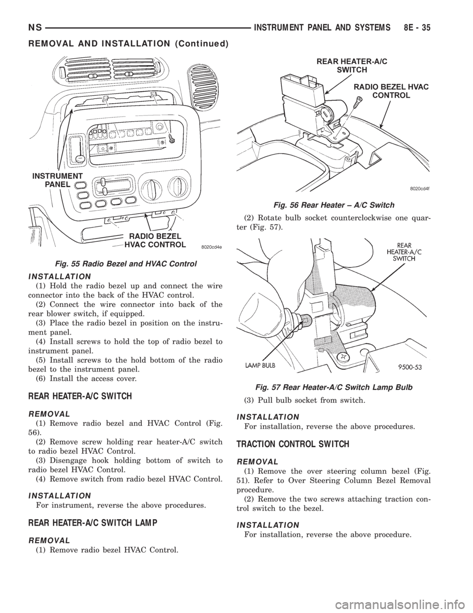
INSTALLATION
(1) Hold the radio bezel up and connect the wire
connector into the back of the HVAC control.
(2) Connect the wire connector into back of the
rear blower switch, if equipped.
(3) Place the radio bezel in position on the instru-
ment panel.
(4) Install screws to hold the top of radio bezel to
instrument panel.
(5) Install screws to the hold bottom of the radio
bezel to the instrument panel.
(6) Install the access cover.
REAR HEATER-A/C SWITCH
REMOVAL
(1) Remove radio bezel and HVAC Control (Fig.
56).
(2) Remove screw holding rear heater-A/C switch
to radio bezel HVAC Control.
(3) Disengage hook holding bottom of switch to
radio bezel HVAC Control.
(4) Remove switch from radio bezel HVAC Control.
INSTALLATION
For instrument, reverse the above procedures.
REAR HEATER-A/C SWITCH LAMP
REMOVAL
(1) Remove radio bezel HVAC Control.(2) Rotate bulb socket counterclockwise one quar-
ter (Fig. 57).
(3) Pull bulb socket from switch.
INSTALLATION
For installation, reverse the above procedures.
TRACTION CONTROL SWITCH
REMOVAL
(1) Remove the over steering column bezel (Fig.
51). Refer to Over Steering Column Bezel Removal
procedure.
(2) Remove the two screws attaching traction con-
trol switch to the bezel.
INSTALLATION
For installation, reverse the above procedure.
Fig. 55 Radio Bezel and HVAC Control
Fig. 56 Rear Heater ± A/C Switch
Fig. 57 Rear Heater-A/C Switch Lamp Bulb
NSINSTRUMENT PANEL AND SYSTEMS 8E - 35
REMOVAL AND INSTALLATION (Continued)
Page 390 of 1938
HEADLAMP SWITCH
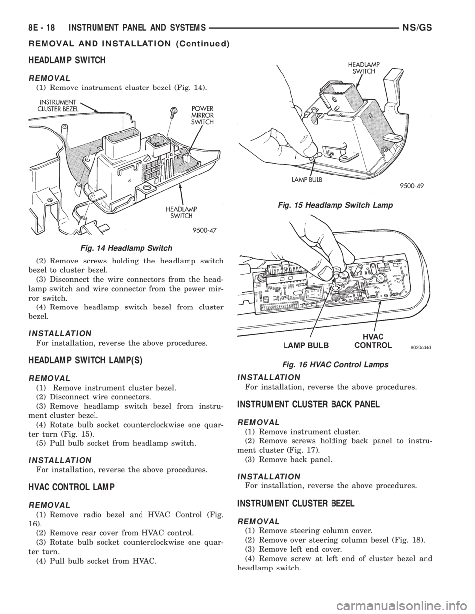
REMOVAL
(1) Remove instrument cluster bezel (Fig. 14).
(2) Remove screws holding the headlamp switch
bezel to cluster bezel.
(3) Disconnect the wire connectors from the head-
lamp switch and wire connector from the power mir-
ror switch.
(4) Remove headlamp switch bezel from cluster
bezel.
INSTALLATION
For installation, reverse the above procedures.
HEADLAMP SWITCH LAMP(S)
REMOVAL
(1) Remove instrument cluster bezel.
(2) Disconnect wire connectors.
(3) Remove headlamp switch bezel from instru-
ment cluster bezel.
(4) Rotate bulb socket counterclockwise one quar-
ter turn (Fig. 15).
(5) Pull bulb socket from headlamp switch.
INSTALLATION
For installation, reverse the above procedures.
HVAC CONTROL LAMP
REMOVAL
(1) Remove radio bezel and HVAC Control (Fig.
16).
(2) Remove rear cover from HVAC control.
(3) Rotate bulb socket counterclockwise one quar-
ter turn.
(4) Pull bulb socket from HVAC.
INSTALLATION
For installation, reverse the above procedures.
INSTRUMENT CLUSTER BACK PANEL
REMOVAL
(1) Remove instrument cluster.
(2) Remove screws holding back panel to instru-
ment cluster (Fig. 17).
(3) Remove back panel.
INSTALLATION
For installation, reverse the above procedures.
INSTRUMENT CLUSTER BEZEL
REMOVAL
(1) Remove steering column cover.
(2) Remove over steering column bezel (Fig. 18).
(3) Remove left end cover.
(4) Remove screw at left end of cluster bezel and
headlamp switch.
Fig. 14 Headlamp Switch
Fig. 15 Headlamp Switch Lamp
Fig. 16 HVAC Control Lamps
8E - 18 INSTRUMENT PANEL AND SYSTEMSNS/GS
REMOVAL AND INSTALLATION (Continued)
Page 400 of 1938
INSTALLATION
(1) Place message center in position on top cover.
(2) Install screws to hold message center to instru-
ment panel top cover.
(3) Connect wire connector into back of message
center.
(4) Install instrument panel top cover.
(5) Install A-pillar trim.
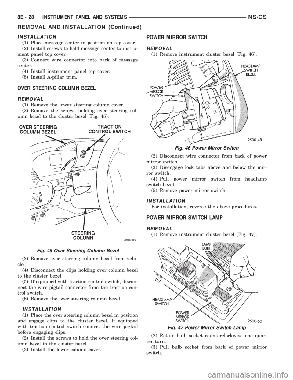
OVER STEERING COLUMN BEZEL
REMOVAL
(1) Remove the lower steering column cover.
(2) Remove the screws holding over steering col-
umn bezel to the cluster bezel (Fig. 45).
(3) Remove over steering column bezel from vehi-
cle.
(4) Disconnect the clips holding over column bezel
to the cluster bezel.
(5) If equipped with traction control switch, discon-
nect the wire pigtail connector from the traction con-
trol switch.
(6) Remove the over steering column bezel.
INSTALLATION
(1) Place the over steering column bezel in position
and engage clips to the cluster bezel. If equipped
with traction control switch connect the wire pigtail
before engaging clips.
(2) Install the screws to hold the over steering col-
umn bezel to the cluster bezel.
(3) Install the lower column cover.
POWER MIRROR SWITCH
REMOVAL
(1) Remove instrument cluster bezel (Fig. 46).
(2) Disconnect wire connector from back of power
mirror switch.
(3) Disengage lock tabs above and below the mir-
ror switch.
(4) Pull power mirror switch from headlamp
switch bezel.
(5) Remove power mirror switch.
INSTALLATION
For installation, reverse the above procedures.
POWER MIRROR SWITCH LAMP
REMOVAL
(1) Remove instrument cluster bezel (Fig. 47).
(2) Rotate bulb socket counterclockwise one quar-
ter turn.
(3) Pull bulb socket from back of power mirror
switch.
Fig. 45 Over Steering Column Bezel
Fig. 46 Power Mirror Switch
Fig. 47 Power Mirror Switch Lamp
8E - 28 INSTRUMENT PANEL AND SYSTEMSNS/GS
REMOVAL AND INSTALLATION (Continued)
Page 401 of 1938
INSTALLATION
For installation, reverse the above procedures.
RADIO BEZEL AND HVAC CONTROL
REMOVAL
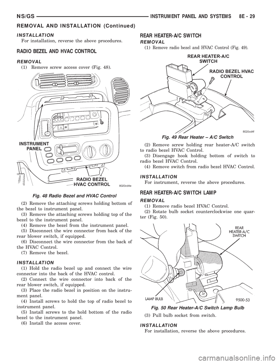
(1) Remove screw access cover (Fig. 48).
(2) Remove the attaching screws holding bottom of
the bezel to instrument panel.
(3) Remove the attaching screws holding top of the
bezel to the instrument panel.
(4) Remove the bezel from the instrument panel.
(5) Disconnect the wire connector from back of the
rear blower switch, if equipped.
(6) Disconnect the wire connector from the back of
the HVAC Control.
(7) Remove the bezel.
INSTALLATION
(1) Hold the radio bezel up and connect the wire
connector into the back of the HVAC control.
(2) Connect the wire connector into back of the
rear blower switch, if equipped.
(3) Place the radio bezel in position on the instru-
ment panel.
(4) Install screws to hold the top of radio bezel to
instrument panel.
(5) Install screws to the hold bottom of the radio
bezel to the instrument panel.
(6) Install the access cover.
REAR HEATER-A/C SWITCH
REMOVAL
(1)Remove radio bezel and HVAC Control (Fig. 49).
(2) Remove screw holding rear heater-A/C switch
to radio bezel HVAC Control.
(3) Disengage hook holding bottom of switch to
radio bezel HVAC Control.
(4) Remove switch from radio bezel HVAC Control.
INSTALLATION
For instrument, reverse the above procedures.
REAR HEATER-A/C SWITCH LAMP
REMOVAL
(1) Remove radio bezel HVAC Control.
(2) Rotate bulb socket counterclockwise one quar-
ter (Fig. 50).
(3) Pull bulb socket from switch.
INSTALLATION
For installation, reverse the above procedures.
Fig. 48 Radio Bezel and HVAC Control
Fig. 49 Rear Heater ± A/C Switch
Fig. 50 Rear Heater-A/C Switch Lamp Bulb
NS/GSINSTRUMENT PANEL AND SYSTEMS 8E - 29
REMOVAL AND INSTALLATION (Continued)
Page 403 of 1938

AUDIO SYSTEMS
CONTENTS
page page
GENERAL INFORMATION
INTRODUCTION......................... 1
DESCRIPTION AND OPERATION
ANTENNA.............................. 1
CHOKEÐINFINITY SPEAKERS.............. 2
INTERFERENCE ELIMINATION.............. 1
NAME BRAND SPEAKER RELAY............ 3
RADIO IGNITION INTERFERENCE........... 2
RADIOS................................ 1
REMOTE RADIO SWITCHES................ 3
DIAGNOSIS AND TESTING
ANTENNA.............................. 3AUDIO SYSTEM......................... 4
RADIO................................. 4
REMOTE RADIO SWITCHES................ 6
REMOVAL AND INSTALLATION
ANTENNA EXTENSION CABLE.............. 7
ANTENNA MAST AND CABLE LEAD......... 7
D±PILLAR SPEAKER.................... 10
FRONT DOOR SPEAKER................... 9
INSTRUMENT PANEL SPEAKER............. 8
QUARTER PANEL SPEAKER............... 10
RADIO/TAPE/CD PLAYER.................. 8
REMOTE RADIO SWITCHES................ 9
GENERAL INFORMATION
INTRODUCTION
Operating instructions for the factory installed
audio systems can be found in the Owner's Manual
provided with the vehicle.
NS vehicles are equipped with an Ignition Off
Draw (IOD) fuse in the power distribution center
located in the engine compartment. After the IOD
fuse or battery has been disconnected, the radio sta-
tion sets and clock will require resetting.
DESCRIPTION AND OPERATION
ANTENNA
All models use a fixed-length stainless steel rod-
type antenna mast, installed at the right front fender
of the vehicle. The antenna mast is connected to the
center wire of the coaxial antenna cable, and is not
grounded to any part of the vehicle.
To eliminate static, the antenna base must have a
good ground. The coaxial antenna cable shield (the
outer wire mesh of the cable) is grounded to the
antenna base and the radio chassis.
The antenna coaxial cable has an additional dis-
connect, located near the right end of the instrument
panel. This additional disconnect allows the instru-
ment panel assembly to be removed and installed
without removing the radio.
The factory-installed Electronically Tuned Radios
(ETRs) automatically compensate for radio antenna
trim. Therefore, no antenna trimmer adjustment isrequired or possible when replacing the receiver or
the antenna.
INTERFERENCE ELIMINATION
Some components used on the vehicles are
equipped with a capacitor to suppress radio fre-
quency interference/static.
Capacitors are mounted in various locations inter-
nal to the generator, instrument cluster and wind-
shield wiper motor.
To eliminate radio interference, ground straps are
used in different areas of the vehicle. These ground
circuits should be securely tightened to assure good
metal to metal contact. The ground straps conduct
very small high frequency electrical signals to ground
and require clean surface contact area. The radio
ground is supplied from the instrument panel har-
ness and is attached to the rear of the radio. Some
engines have other ground straps to eliminate fur-
ther radio interference:
²Radio chassis to instrument panel structure
²Engine to dash panel
²Engine to chassis
²A/C h valve to dash panel
Radio resistance type spark plug cables in the high
tension circuit of the ignition system complete the
interference suppression. Faulty or deteriorated
spark plug wires should be replaced.
RADIOS
Available factory-installed radio receivers for this
model include an AM/FM/cassette (RAS sales code),
an AM/FM/cassette/5-band graphic equalizer with CD
changer control feature (RBN sales code), an AM/FM/
NSAUDIO SYSTEMS 8F - 1
Page 404 of 1938

CD/3-band graphic equalizer (RBR sales code), or an
AM/FM/CD/cassette/3-band graphic equalizer (RAZ
sales code).
All factory-installed radio receivers are stereo Elec-
tronically Tuned Radios (ETR) and include an elec-
tronic digital clock function.
All factory-installed radio receivers, except the
RAS model, communicate on the Chrysler Collision
Detection (CCD) data bus network through a sepa-
rate two-way wire harness connector. The CCD data
bus network allows the sharing of sensor informa-
tion. This helps to reduce wire harness complexity,
internal controller hardware, and component sensor
current loads. At the same time, this system provides
increased reliability, enhanced diagnostics, and
allows the addition of many new feature capabilities.
In addition, radios connected to the CCD data bus
have several audio system functions that can be diag-
nosed using a DRB scan tool. Refer to the proper
Diagnostic Procedures manual for more information
on DRB testing of the audio systems.
The radio can only be serviced by an authorized
radio repair station. Refer to the latest Warranty Pol-
icies and Procedures manual for a current listing of
authorized radio repair stations.
For more information on radio features, setting
procedures, and control functions refer to the owner's
manual in the vehicle glove box.
RADIO IGNITION INTERFERENCE
If receiving ignition/engine interference noise on
the radio stations, check and clean all engine and
body ground connections. Tighten properly after
cleaning. Example (Fig. 1), (Fig. 2), (Fig. 3) and (Fig.
4).
Ensure all ground connections are without corro-
sion.
CHOKEÐINFINITY SPEAKERS
If the audio system is lacking bass response, check
for continuity across the choke connector. If no conti-
nuity Replace choke. The choke is located on the
Fig. 1 Motor Mount to Frame Rail Ground
Fig. 2 2.4L Engine Block Ground
Fig. 3 3.0L Engine Block Ground
Fig. 4 3.3/3.8L Engine Block Ground
8F - 2 AUDIO SYSTEMSNS
DESCRIPTION AND OPERATION (Continued)