clock CHRYSLER VOYAGER 1996 Service Manual
[x] Cancel search | Manufacturer: CHRYSLER, Model Year: 1996, Model line: VOYAGER, Model: CHRYSLER VOYAGER 1996Pages: 1938, PDF Size: 55.84 MB
Page 1699 of 1938
INSTALLATION
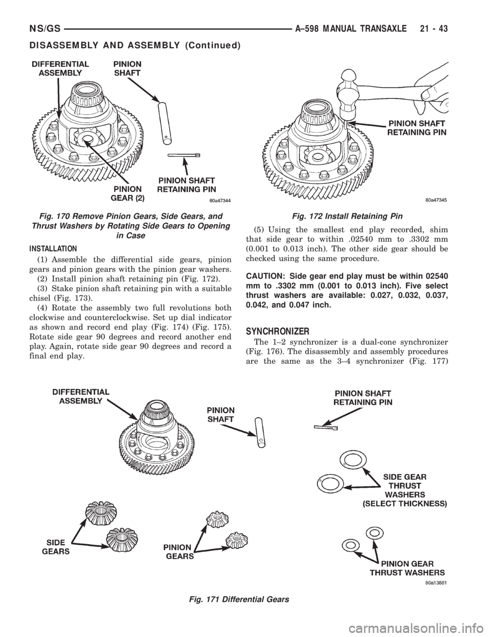
(1) Assemble the differential side gears, pinion
gears and pinion gears with the pinion gear washers.
(2) Install pinion shaft retaining pin (Fig. 172).
(3) Stake pinion shaft retaining pin with a suitable
chisel (Fig. 173).
(4) Rotate the assembly two full revolutions both
clockwise and counterclockwise. Set up dial indicator
as shown and record end play (Fig. 174) (Fig. 175).
Rotate side gear 90 degrees and record another end
play. Again, rotate side gear 90 degrees and record a
final end play.(5) Using the smallest end play recorded, shim
that side gear to within .02540 mm to .3302 mm
(0.001 to 0.013 inch). The other side gear should be
checked using the same procedure.
CAUTION: Side gear end play must be within 02540
mm to .3302 mm (0.001 to 0.013 inch). Five select
thrust washers are available: 0.027, 0.032, 0.037,
0.042, and 0.047 inch.
SYNCHRONIZER
The 1±2 synchronizer is a dual-cone synchronizer
(Fig. 176). The disassembly and assembly procedures
are the same as the 3±4 synchronizer (Fig. 177)
Fig. 171 Differential Gears
Fig. 170 Remove Pinion Gears, Side Gears, and
Thrust Washers by Rotating Side Gears to Opening
in CaseFig. 172 Install Retaining Pin
NS/GSA±598 MANUAL TRANSAXLE 21 - 43
DISASSEMBLY AND ASSEMBLY (Continued)
Page 1749 of 1938
INSTALLATION
(1) Place heated seat module in position on seat
pan.
(2) Install module attaching screws.
(3) Connect module wire connectors.
(4) Install seat.
HEATED SEAT SWITCH
Diagnostic information for heated seat switch is
located in Group 8R, Power Seats.
REMOVAL
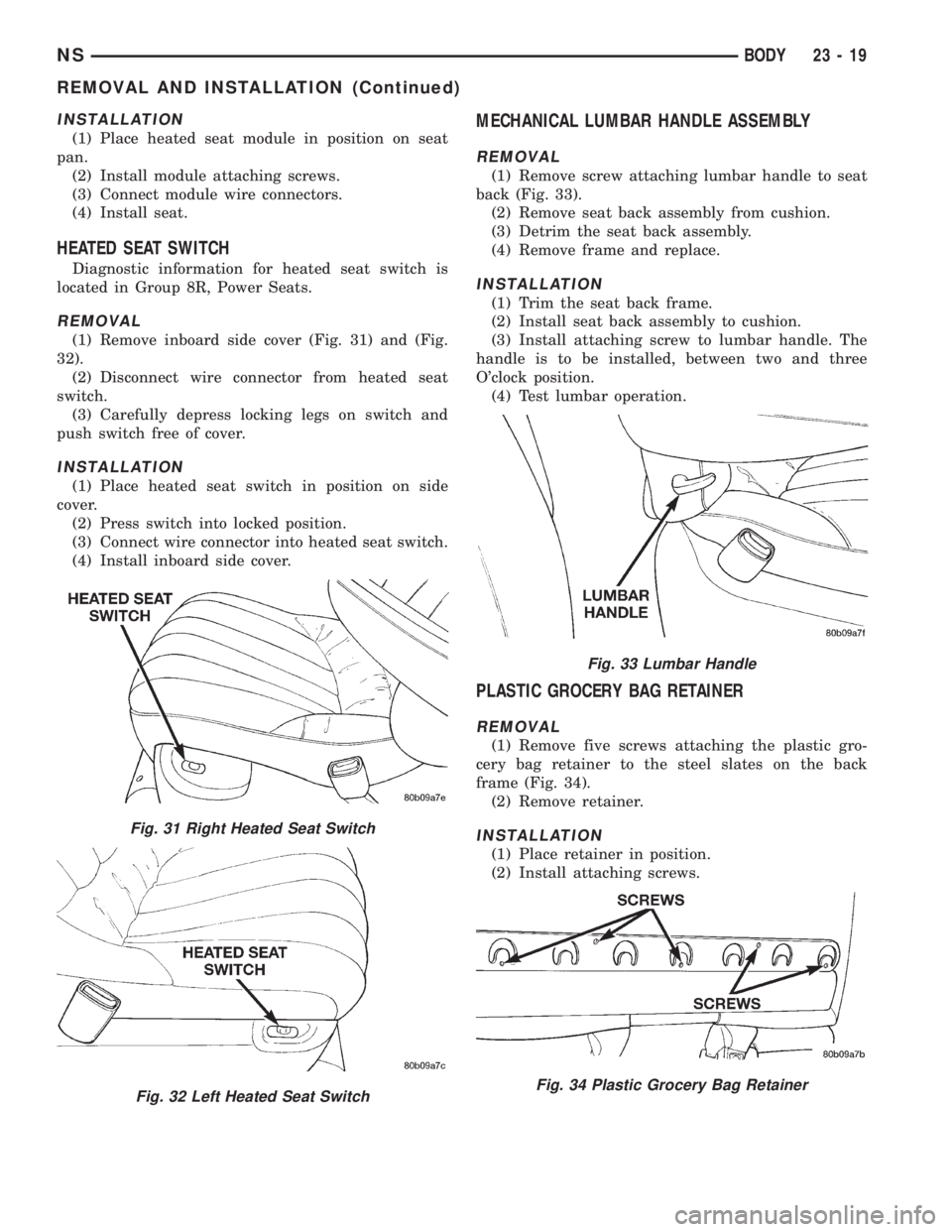
(1) Remove inboard side cover (Fig. 31) and (Fig.
32).
(2) Disconnect wire connector from heated seat
switch.
(3) Carefully depress locking legs on switch and
push switch free of cover.
INSTALLATION
(1) Place heated seat switch in position on side
cover.
(2) Press switch into locked position.
(3) Connect wire connector into heated seat switch.
(4) Install inboard side cover.
MECHANICAL LUMBAR HANDLE ASSEMBLY
REMOVAL
(1) Remove screw attaching lumbar handle to seat
back (Fig. 33).
(2) Remove seat back assembly from cushion.
(3) Detrim the seat back assembly.
(4) Remove frame and replace.
INSTALLATION
(1) Trim the seat back frame.
(2) Install seat back assembly to cushion.
(3) Install attaching screw to lumbar handle. The
handle is to be installed, between two and three
O'clock position.
(4) Test lumbar operation.
PLASTIC GROCERY BAG RETAINER
REMOVAL
(1) Remove five screws attaching the plastic gro-
cery bag retainer to the steel slates on the back
frame (Fig. 34).
(2) Remove retainer.
INSTALLATION
(1) Place retainer in position.
(2) Install attaching screws.
Fig. 31 Right Heated Seat Switch
Fig. 32 Left Heated Seat Switch
Fig. 33 Lumbar Handle
Fig. 34 Plastic Grocery Bag Retainer
NSBODY 23 - 19
REMOVAL AND INSTALLATION (Continued)
Page 1810 of 1938
UPPER C-PILLAR TRIM
REMOVAL
(1) Remove quarter trim bolster.
(2) Remove seat belt turning loop from height
adjuster.
(3) Remove screw holding C-pillar trim panel to
C-pillar on right side of SWB vehicle.
(4) Disengage hidden clips holding trim to upper
C-pillar.
(5) Remove upper C-pillar trim from vehicle.
INSTALLATION
(1) Place upper C-pillar trim in position on vehicle.
(2) Engage hidden clips to hold trim to upper
C-pillar.
(3) Install screw to hold C-pillar trim panel to
C-pillar on right side of SWB vehicle.
(4) Install seat belt turning loop onto height
adjuster. Tighten all seat belt bolts to 39 N´m (29 in.
lbs.) torque.
(5) Install quarter trim bolster.
ADJUSTMENTS
SLIDING DOOR ADJUSTMENTS
PRELIMINARY CHECKS
(1) Close sliding door, visually checking C-post
striker alignment entry into latch. Striker at this
point must not affect alignment.(2) On vehicles with left sliding doors, check the
fuel door blocker striker entry into latch. Striker at
this point must not affect alignment.
(3) Check C-post and B-post for door to aperture
gaps and door to door gaps. All gaps should be 5 mm
61 mm.
(4) C
heck door for height using character lines as a
reference. Also check roof contour as a controlling factor.
UP/DOWN ADJUSTMENT
(1) Visually inspect the sliding door for fitting low
at the rear of the door by checking the alignment of
the belt line of the door to quarter panel.
(2) Fully open the sliding door.
(3) Verify that all center hinge bolts are tight.
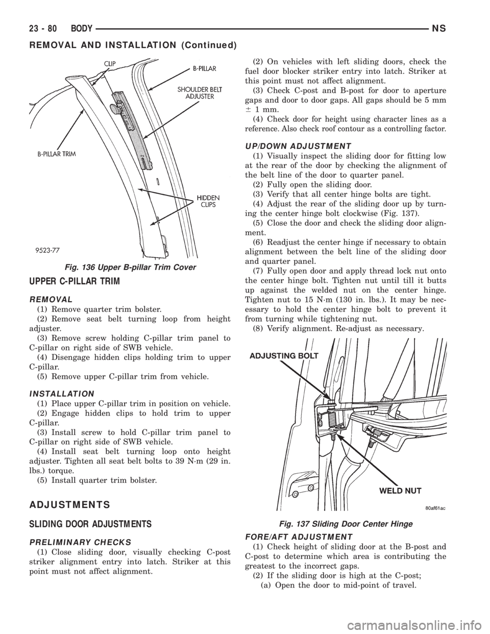
(4) Adjust the rear of the sliding door up by turn-
ing the center hinge bolt clockwise (Fig. 137).
(5) Close the door and check the sliding door align-
ment.
(6) Readjust the center hinge if necessary to obtain
alignment between the belt line of the sliding door
and quarter panel.
(7) Fully open door and apply thread lock nut onto
the center hinge bolt. Tighten nut until till it butts
up against the welded nut on the center hinge.
Tighten nut to 15 N´m (130 in. lbs.). It may be nec-
essary to hold the center hinge bolt to prevent it
from turning while tightening nut.
(8) Verify alignment. Re-adjust as necessary.
FORE/AFT ADJUSTMENT
(1) Check height of sliding door at the B-post and
C-post to determine which area is contributing the
greatest to the incorrect gaps.
(2) If the sliding door is high at the C-post;
(a) Open the door to mid-point of travel.
Fig. 136 Upper B-pillar Trim Cover
Fig. 137 Sliding Door Center Hinge
23 - 80 BODYNS
REMOVAL AND INSTALLATION (Continued)
Page 1862 of 1938
REAR HEATER A/C BLOWER MOTOR
REMOVAL
(1) Remove the right quarter trim panel and D-pil-
lar trim. Refer to Group 23, Body for service proce-
dures.
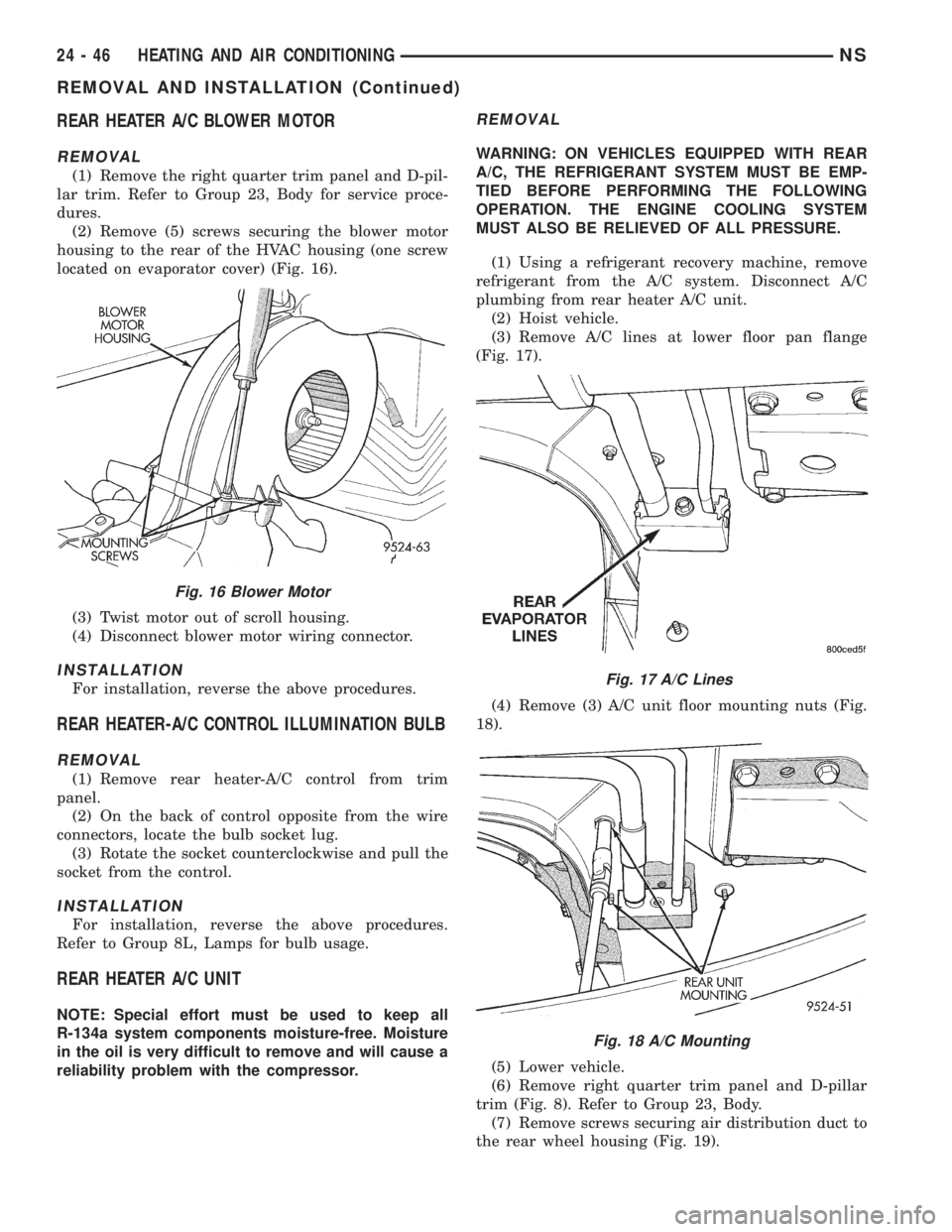
(2) Remove (5) screws securing the blower motor
housing to the rear of the HVAC housing (one screw
located on evaporator cover) (Fig. 16).
(3) Twist motor out of scroll housing.
(4) Disconnect blower motor wiring connector.
INSTALLATION
For installation, reverse the above procedures.
REAR HEATER-A/C CONTROL ILLUMINATION BULB
REMOVAL
(1) Remove rear heater-A/C control from trim
panel.
(2) On the back of control opposite from the wire
connectors, locate the bulb socket lug.
(3) Rotate the socket counterclockwise and pull the
socket from the control.
INSTALLATION
For installation, reverse the above procedures.
Refer to Group 8L, Lamps for bulb usage.
REAR HEATER A/C UNIT
NOTE: Special effort must be used to keep all
R-134a system components moisture-free. Moisture
in the oil is very difficult to remove and will cause a
reliability problem with the compressor.
REMOVAL
WARNING: ON VEHICLES EQUIPPED WITH REAR
A/C, THE REFRIGERANT SYSTEM MUST BE EMP-
TIED BEFORE PERFORMING THE FOLLOWING
OPERATION. THE ENGINE COOLING SYSTEM
MUST ALSO BE RELIEVED OF ALL PRESSURE.
(1) Using a refrigerant recovery machine, remove
refrigerant from the A/C system. Disconnect A/C
plumbing from rear heater A/C unit.
(2) Hoist vehicle.
(3) Remove A/C lines at lower floor pan flange
(Fig. 17).
(4) Remove (3) A/C unit floor mounting nuts (Fig.
18).
(5) Lower vehicle.
(6) Remove right quarter trim panel and D-pillar
trim (Fig. 8). Refer to Group 23, Body.
(7) Remove screws securing air distribution duct to
the rear wheel housing (Fig. 19).
Fig. 16 Blower Motor
Fig. 17 A/C Lines
Fig. 18 A/C Mounting
24 - 46 HEATING AND AIR CONDITIONINGNS
REMOVAL AND INSTALLATION (Continued)
Page 1914 of 1938
The primary components within the assembly are:
A three port solenoid that activates both of the func-
tions listed above; a pump which contains a switch,
two check valves and a spring/diaphragm, a canister
vent valve (CVV) seal which contains a spring loaded
vent seal valve.
Immediately after a cold start, between predeter-
mined temperature thresholds limits, the three port
solenoid is briefly energized. This initializes the
pump by drawing air into the pump cavity and also
closes the vent seal. During non test conditions the
vent seal is held open by the pump diaphragm
assembly which pushes it open at the full travel posi-
tion. The vent seal will remain closed while the
pump is cycling due to the reed switch triggering of
the three port solenoid that prevents the diaphragm
assembly from reaching full travel. After the brief
initialization period, the solenoid is de-energized
allowing atmospheric pressure to enter the pump
cavity, thus permitting the spring to drive the dia-
phragm which forces air out of the pump cavity and
into the vent system. When the solenoid is energized
and de energized, the cycle is repeated creating flow
in typical diaphragm pump fashion. The pump is con-
trolled in 2 modes:
Pump Mode:The pump is cycled at a fixed rate to
achieve a rapid pressure build in order to shorten the
overall test length.
Test Mode:The solenoid is energized with a fixed
duration pulse. Subsequent fixed pulses occur when
the diaphragm reaches the Switch closure point.
The spring in the pump is set so that the system
will achieve an equalized pressure of about 7.5º H20.
The cycle rate of pump strokes is quite rapid as the
system begins to pump up to this pressure. As the
pressure increases, the cycle rate starts to drop off. If
there is no leak in the system, the pump would even-
tually stop pumping at the equalized pressure. If
there is a leak, it will continue to pump at a rate rep-
resentative of the flow characteristic of the size of the
leak. From this information we can determine if the
leak is larger than the required detection limit (cur-
rently set at .020º orifice by CARB). If a leak is
revealed during the leak test portion of the test, the
test is terminated at the end of the test mode and no
further system checks will be performed.
After passing the leak detection phase of the test,
system pressure is maintained by turning on the
LDP's solenoid until the purge system is activated.
Purge activation in effect creates a leak. The cycle
rate is again interrogated and when it increases due
to the flow through the purge system, the leak check
portion of the diagnostic is complete.
The canister vent valve will unseal the system
after completion of the test sequence as the pumpdiaphragm assembly moves to the full travel position.
Evaporative system functionality will be verified by
using the stricter evap purge flow monitor. At an
appropriate warm idle the LDP will be energized to
seal the canister vent. The purge flow will be clocked
up from some small value in an attempt to see a
shift in the 02 control system. If fuel vapor, indicated
by a shift in the 02 control, is present the test is
passed. If not, it is assumed that the purge system is
not functioning in some respect. The LDP is again
turned off and the test is ended.
TRIP DEFINITION
A ªTripº means vehicle operation (following an
engine-off period) of duration and driving mode such
that all components and systems are monitored at
least once by the diagnostic system. The monitors
must successfully pass before the PCM can verify
that a previously malfunctioning component is meet-
ing the normal operating conditions of that compo-
nent. For misfire or fuel system malfunction, the
MIL may be extinguished if the fault does not recur
when monitored during three subsequent sequential
driving cycles in which conditions are similar to
those under which the malfunction was first deter-
mined.
Anytime the MIL is illuminated, a DTC is stored.
The DTC can self erase only when the MIL has been
extinguished. Once the MIL is extinguished, the
PCM must pass the diagnostic test for the most
recent DTC for 40 warm-up cycles (80 warm-up
cycles for the Fuel System Monitor and the Misfire
Monitor). A warm-up cycle can best be described by
the following:
²The engine must be running
²A rise of 40ÉF in engine temperature must occur
from the time when the engine was started
²Engine coolant temperature must reach at least
160ÉF
²A ªdriving cycleº that consists of engine start up
and engine shut off.
Once the above conditions occur, the PCM is con-
sidered to have passed a warm-up cycle. Due to the
conditions required to extinguish the MIL and erase
the DTC, it is most important that after a repair has
been made, all DTC's be erased and the repair veri-
fied.
COMPONENT MONITORS
There are several components that will affect vehi-
cle emissions if they malfunction. If one of these com-
ponents malfunctions the Malfunction Indicator
Lamp (Check Engine) will illuminate.
Some of the component monitors are checking for
proper operation of the part. Electrically operated
25 - 10 EMISSION CONTROL SYSTEMSNS
DESCRIPTION AND OPERATION (Continued)