clock CHRYSLER VOYAGER 1996 Owner's Guide
[x] Cancel search | Manufacturer: CHRYSLER, Model Year: 1996, Model line: VOYAGER, Model: CHRYSLER VOYAGER 1996Pages: 1938, PDF Size: 55.84 MB
Page 467 of 1938
INSTALLATION
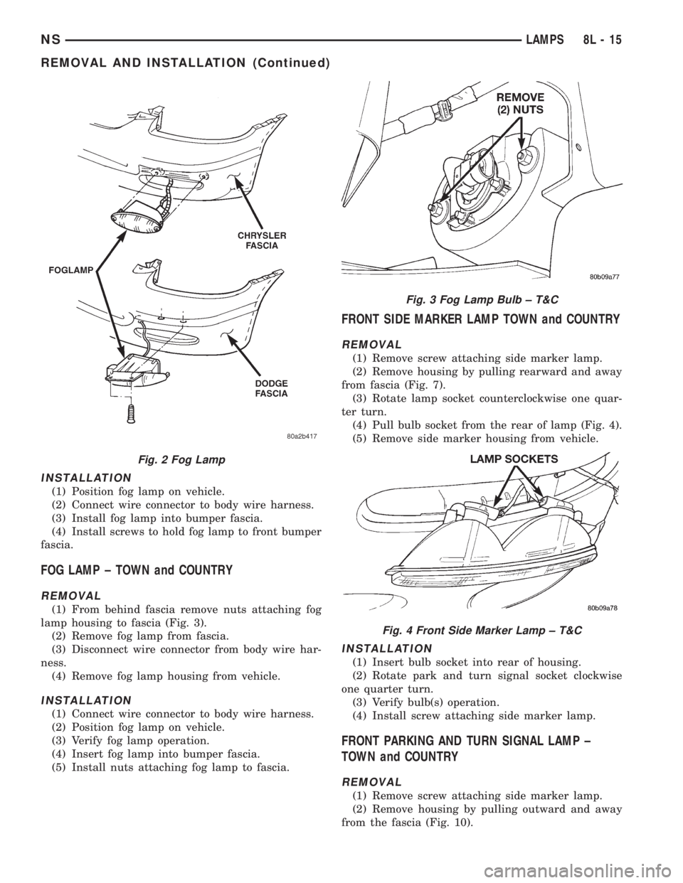
(1) Position fog lamp on vehicle.
(2) Connect wire connector to body wire harness.
(3) Install fog lamp into bumper fascia.
(4) Install screws to hold fog lamp to front bumper
fascia.
FOG LAMP ± TOWN and COUNTRY
REMOVAL
(1) From behind fascia remove nuts attaching fog
lamp housing to fascia (Fig. 3).
(2) Remove fog lamp from fascia.
(3) Disconnect wire connector from body wire har-
ness.
(4) Remove fog lamp housing from vehicle.
INSTALLATION
(1) Connect wire connector to body wire harness.
(2) Position fog lamp on vehicle.
(3) Verify fog lamp operation.
(4) Insert fog lamp into bumper fascia.
(5) Install nuts attaching fog lamp to fascia.
FRONT SIDE MARKER LAMP TOWN and COUNTRY
REMOVAL
(1) Remove screw attaching side marker lamp.
(2) Remove housing by pulling rearward and away
from fascia (Fig. 7).
(3) Rotate lamp socket counterclockwise one quar-
ter turn.
(4) Pull bulb socket from the rear of lamp (Fig. 4).
(5) Remove side marker housing from vehicle.
INSTALLATION
(1) Insert bulb socket into rear of housing.
(2) Rotate park and turn signal socket clockwise
one quarter turn.
(3) Verify bulb(s) operation.
(4) Install screw attaching side marker lamp.
FRONT PARKING AND TURN SIGNAL LAMP ±
TOWN and COUNTRY
REMOVAL
(1) Remove screw attaching side marker lamp.
(2) Remove housing by pulling outward and away
from the fascia (Fig. 10).
Fig. 2 Fog Lamp
Fig. 3 Fog Lamp Bulb ± T&C
Fig. 4 Front Side Marker Lamp ± T&C
NSLAMPS 8L - 15
REMOVAL AND INSTALLATION (Continued)
Page 468 of 1938
(3) Remove screw attaching parking and turn sig-
nal lamp housing to fascia.
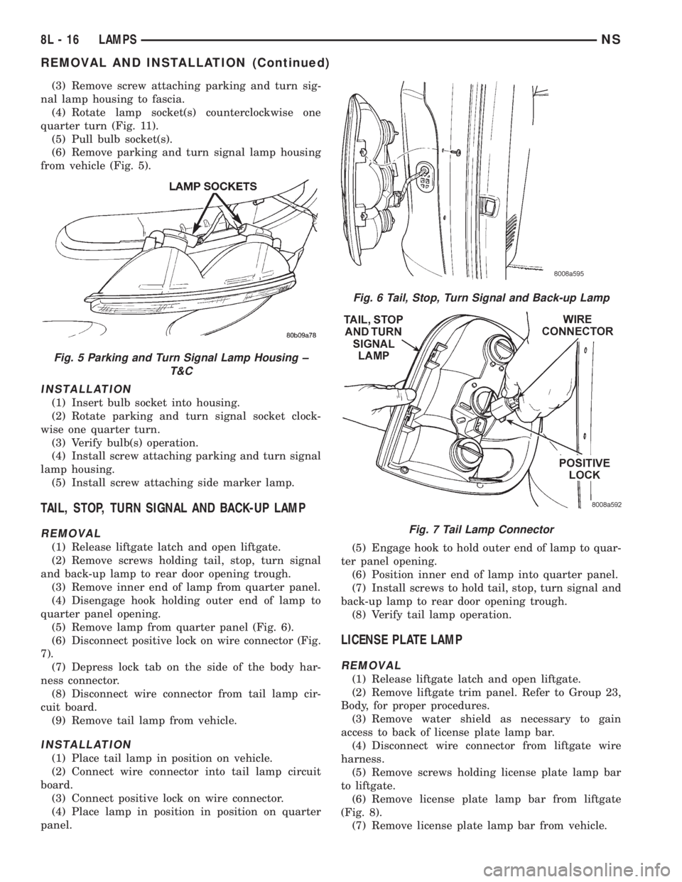
(4) Rotate lamp socket(s) counterclockwise one
quarter turn (Fig. 11).
(5) Pull bulb socket(s).
(6) Remove parking and turn signal lamp housing
from vehicle (Fig. 5).
INSTALLATION
(1) Insert bulb socket into housing.
(2) Rotate parking and turn signal socket clock-
wise one quarter turn.
(3) Verify bulb(s) operation.
(4) Install screw attaching parking and turn signal
lamp housing.
(5) Install screw attaching side marker lamp.
TAIL, STOP, TURN SIGNAL AND BACK-UP LAMP
REMOVAL
(1) Release liftgate latch and open liftgate.
(2) Remove screws holding tail, stop, turn signal
and back-up lamp to rear door opening trough.
(3) Remove inner end of lamp from quarter panel.
(4) Disengage hook holding outer end of lamp to
quarter panel opening.
(5) Remove lamp from quarter panel (Fig. 6).
(6) Disconnect positive lock on wire connector (Fig.
7).
(7) Depress lock tab on the side of the body har-
ness connector.
(8) Disconnect wire connector from tail lamp cir-
cuit board.
(9) Remove tail lamp from vehicle.
INSTALLATION
(1) Place tail lamp in position on vehicle.
(2) Connect wire connector into tail lamp circuit
board.
(3) Connect positive lock on wire connector.
(4) Place lamp in position in position on quarter
panel.(5) Engage hook to hold outer end of lamp to quar-
ter panel opening.
(6) Position inner end of lamp into quarter panel.
(7) Install screws to hold tail, stop, turn signal and
back-up lamp to rear door opening trough.
(8) Verify tail lamp operation.
LICENSE PLATE LAMP
REMOVAL
(1) Release liftgate latch and open liftgate.
(2) Remove liftgate trim panel. Refer to Group 23,
Body, for proper procedures.
(3) Remove water shield as necessary to gain
access to back of license plate lamp bar.
(4) Disconnect wire connector from liftgate wire
harness.
(5) Remove screws holding license plate lamp bar
to liftgate.
(6) Remove license plate lamp bar from liftgate
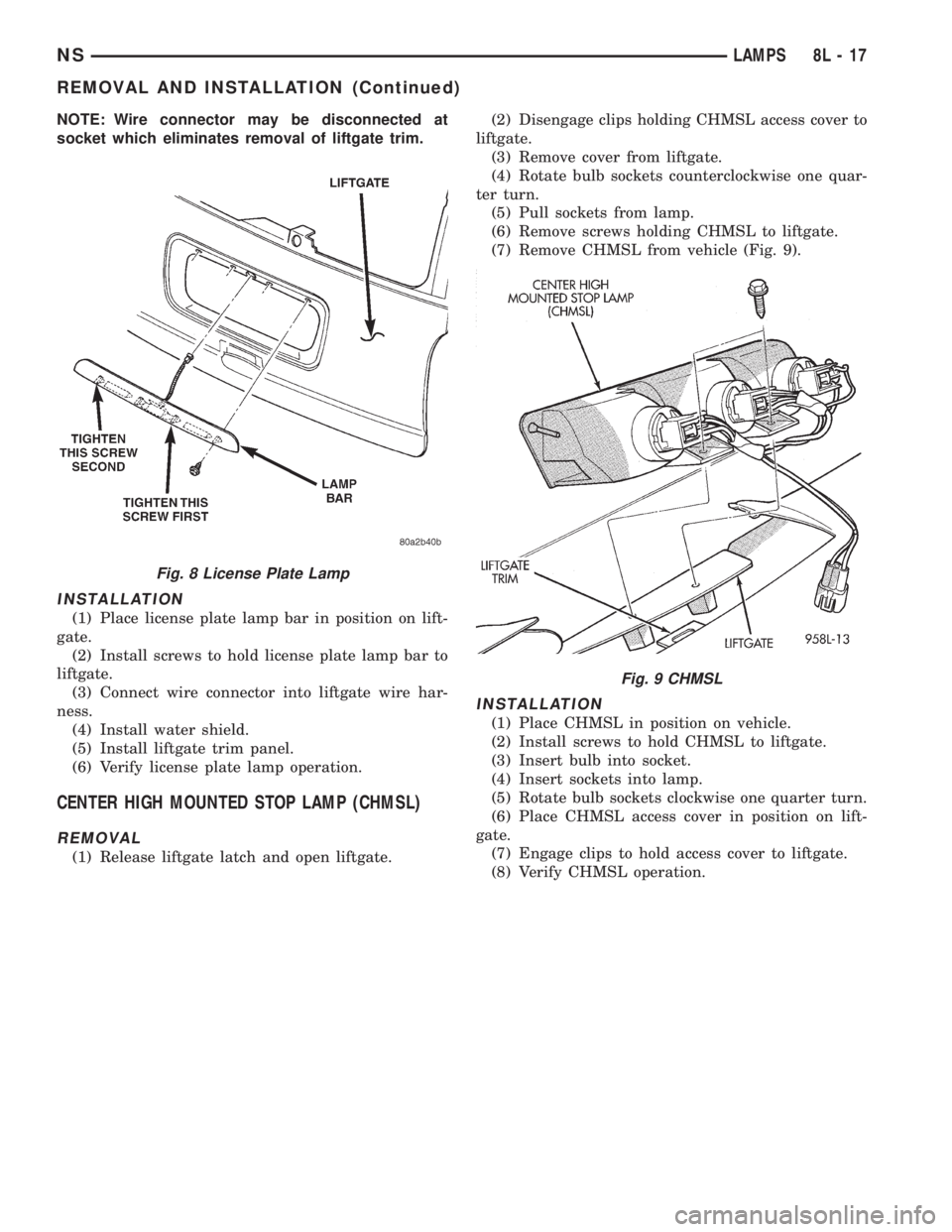
(Fig. 8).
(7) Remove license plate lamp bar from vehicle.
Fig. 5 Parking and Turn Signal Lamp Housing ±
T&C
Fig. 6 Tail, Stop, Turn Signal and Back-up Lamp
Fig. 7 Tail Lamp Connector
8L - 16 LAMPSNS
REMOVAL AND INSTALLATION (Continued)
Page 469 of 1938
NOTE: Wire connector may be disconnected at
socket which eliminates removal of liftgate trim.
INSTALLATION
(1) Place license plate lamp bar in position on lift-
gate.
(2) Install screws to hold license plate lamp bar to
liftgate.
(3) Connect wire connector into liftgate wire har-
ness.
(4) Install water shield.
(5) Install liftgate trim panel.
(6) Verify license plate lamp operation.
CENTER HIGH MOUNTED STOP LAMP (CHMSL)
REMOVAL
(1) Release liftgate latch and open liftgate.(2) Disengage clips holding CHMSL access cover to
liftgate.
(3) Remove cover from liftgate.
(4) Rotate bulb sockets counterclockwise one quar-
ter turn.
(5) Pull sockets from lamp.
(6) Remove screws holding CHMSL to liftgate.
(7) Remove CHMSL from vehicle (Fig. 9).
INSTALLATION
(1) Place CHMSL in position on vehicle.
(2) Install screws to hold CHMSL to liftgate.
(3) Insert bulb into socket.
(4) Insert sockets into lamp.
(5) Rotate bulb sockets clockwise one quarter turn.
(6) Place CHMSL access cover in position on lift-
gate.
(7) Engage clips to hold access cover to liftgate.
(8) Verify CHMSL operation.
Fig. 8 License Plate Lamp
Fig. 9 CHMSL
NSLAMPS 8L - 17
REMOVAL AND INSTALLATION (Continued)
Page 470 of 1938
INTERIOR LAMPS
INDEX
page page
REMOVAL AND INSTALLATION
CONVENIENCE BIN LAMP................. 20
DOME LAMP BULB...................... 21
DOME LAMP........................... 21
FRONT DOOR COURTESY LAMP BULB...... 22
FRONT DOOR COURTESY LAMP........... 21
GLOVE BOX LAMP AND SWITCH........... 19
GLOVE BOX LAMP BULB.................. 19
HEADER READING/COURTESY LAMP BULB . . . 19HEADER READING/COURTESY LAMP....... 18
IGNITION HALO LAMP BULB............... 19
INSTRUMENT PANEL LAMPS AND SWITCHES . 20
LIFTGATE COURTESY LAMP BULB.......... 24
LIFTGATE COURTESY LAMP............... 23
OVERHEAD CONSOLE READING/COURTESY
LAMP BULB.......................... 18
RAIL LAMP MODULE BULB................ 23
REMOVAL AND INSTALLATION
OVERHEAD CONSOLE READING/COURTESY LAMP
BULB
REMOVAL
(1) Using a trim stick, lightly pry outward the for-
ward end of reading lamp lens.
(2) Rotate reading lamp bulb socket one quarter
turn counterclockwise.
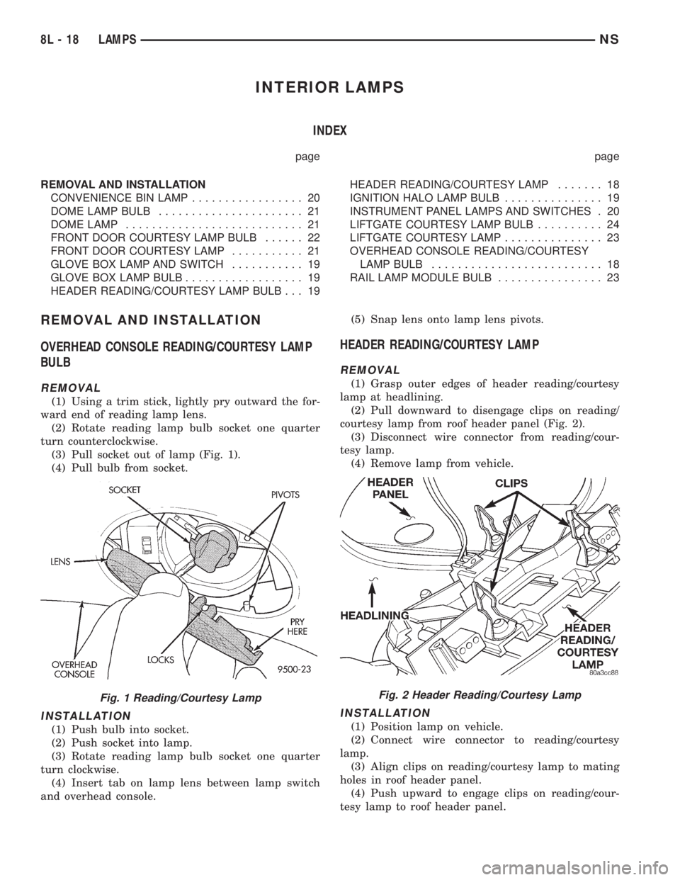
(3) Pull socket out of lamp (Fig. 1).
(4) Pull bulb from socket.
INSTALLATION
(1) Push bulb into socket.
(2) Push socket into lamp.
(3) Rotate reading lamp bulb socket one quarter
turn clockwise.
(4) Insert tab on lamp lens between lamp switch
and overhead console.(5) Snap lens onto lamp lens pivots.
HEADER READING/COURTESY LAMP
REMOVAL
(1) Grasp outer edges of header reading/courtesy
lamp at headlining.
(2) Pull downward to disengage clips on reading/
courtesy lamp from roof header panel (Fig. 2).
(3) Disconnect wire connector from reading/cour-
tesy lamp.
(4) Remove lamp from vehicle.
INSTALLATION
(1) Position lamp on vehicle.
(2) Connect wire connector to reading/courtesy
lamp.
(3) Align clips on reading/courtesy lamp to mating
holes in roof header panel.
(4) Push upward to engage clips on reading/cour-
tesy lamp to roof header panel.
Fig. 1 Reading/Courtesy LampFig. 2 Header Reading/Courtesy Lamp
8L - 18 LAMPSNS
Page 472 of 1938
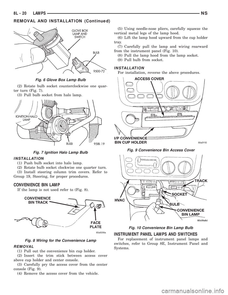
(2) Rotate bulb socket counterclockwise one quar-
ter turn (Fig. 7).
(3) Pull bulb socket from halo lamp.
INSTALLATION
(1) Push bulb socket into halo lamp.
(2) Rotate bulb socket clockwise one quarter turn.
(3) Install steering column trim covers. Refer to
Group 19, Steering, for proper procedures.
CONVENIENCE BIN LAMP
If the lamp is not used refer to (Fig. 8).
REMOVAL
(1) Pull out the convenience bin cup holder.
(2) Insert the trim stick between access cover
above cup holder and center console.
(3) Carefully pry the access cover from the center
console (Fig. 9).
(4) Remove the access cover from the vehicle.(5) Using needle-nose pliers, carefully squeeze the
vertical metal legs of the lamp hood.
(6) Lift the lamp hood upward from the cup holder
tray.
(7) Carefully pull the lamp and wiring rearward
from the instrument panel (Fig. 10).
(8) Pull the lamp hood from the lamp socket.
(9) Pull bulb from socket.
INSTALLATION
For installation, reverse the above procedures.
INSTRUMENT PANEL LAMPS AND SWITCHES
For replacement of instrument panel lamps and
switches, refer to Group 8E, Instrument Panel and
Systems.
Fig. 6 Glove Box Lamp Bulb
Fig. 7 Ignition Halo Lamp Bulb
Fig. 8 Wiring for the Convenience Lamp
Fig. 9 Convenience Bin Access Cover
Fig. 10 Convenience Bin Lamp Bulb
8L - 20 LAMPSNS
REMOVAL AND INSTALLATION (Continued)
Page 487 of 1938
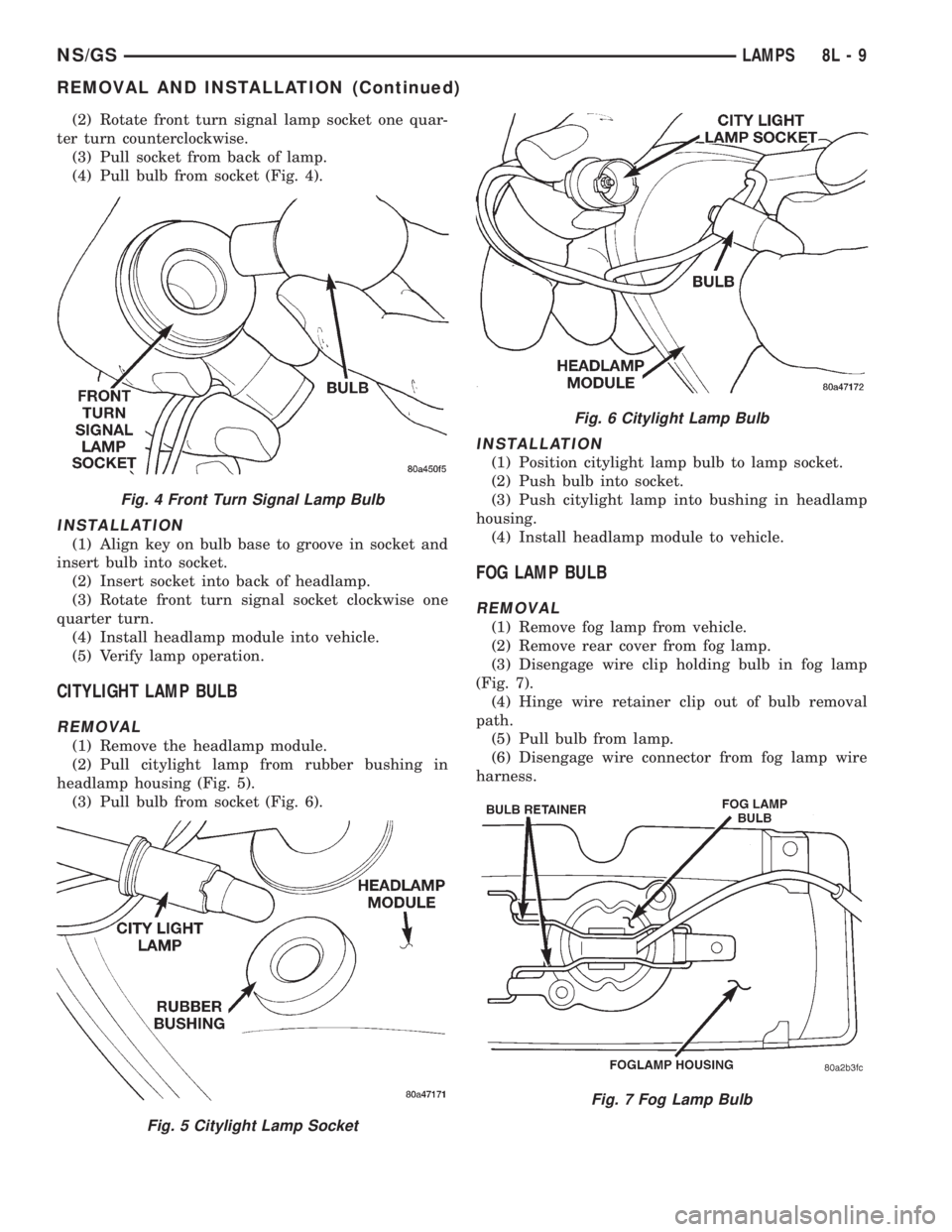
(2) Rotate front turn signal lamp socket one quar-
ter turn counterclockwise.
(3) Pull socket from back of lamp.
(4) Pull bulb from socket (Fig. 4).
INSTALLATION
(1) Align key on bulb base to groove in socket and
insert bulb into socket.
(2) Insert socket into back of headlamp.
(3) Rotate front turn signal socket clockwise one
quarter turn.
(4) Install headlamp module into vehicle.
(5) Verify lamp operation.
CITYLIGHT LAMP BULB
REMOVAL
(1) Remove the headlamp module.
(2) Pull citylight lamp from rubber bushing in
headlamp housing (Fig. 5).
(3) Pull bulb from socket (Fig. 6).
INSTALLATION
(1) Position citylight lamp bulb to lamp socket.
(2) Push bulb into socket.
(3) Push citylight lamp into bushing in headlamp
housing.
(4) Install headlamp module to vehicle.
FOG LAMP BULB
REMOVAL
(1) Remove fog lamp from vehicle.
(2) Remove rear cover from fog lamp.
(3) Disengage wire clip holding bulb in fog lamp
(Fig. 7).
(4) Hinge wire retainer clip out of bulb removal
path.
(5) Pull bulb from lamp.
(6) Disengage wire connector from fog lamp wire
harness.
Fig. 4 Front Turn Signal Lamp Bulb
Fig. 5 Citylight Lamp Socket
Fig. 6 Citylight Lamp Bulb
Fig. 7 Fog Lamp Bulb
NS/GSLAMPS 8L - 9
REMOVAL AND INSTALLATION (Continued)
Page 492 of 1938
HEADLAMP LEVELING MOTOR
REMOVAL
(1) Remove headlamp module from vehicle.
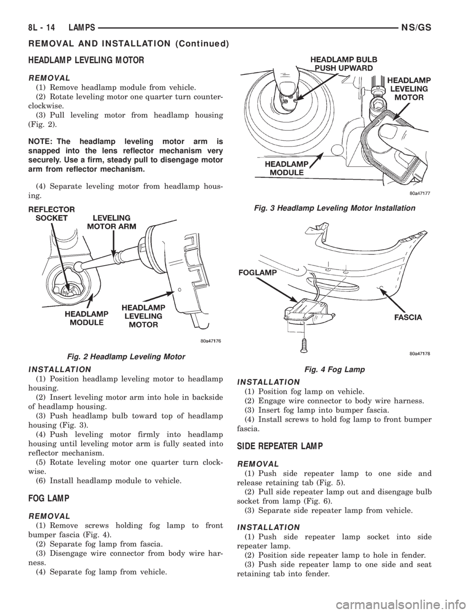
(2) Rotate leveling motor one quarter turn counter-
clockwise.
(3) Pull leveling motor from headlamp housing
(Fig. 2).
NOTE: The headlamp leveling motor arm is
snapped into the lens reflector mechanism very
securely. Use a firm, steady pull to disengage motor
arm from reflector mechanism.
(4) Separate leveling motor from headlamp hous-
ing.
INSTALLATION
(1) Position headlamp leveling motor to headlamp
housing.
(2) Insert leveling motor arm into hole in backside
of headlamp housing.
(3) Push headlamp bulb toward top of headlamp
housing (Fig. 3).
(4) Push leveling motor firmly into headlamp
housing until leveling motor arm is fully seated into
reflector mechanism.
(5) Rotate leveling motor one quarter turn clock-
wise.
(6) Install headlamp module to vehicle.
FOG LAMP
REMOVAL
(1) Remove screws holding fog lamp to front
bumper fascia (Fig. 4).
(2) Separate fog lamp from fascia.
(3) Disengage wire connector from body wire har-
ness.
(4) Separate fog lamp from vehicle.
INSTALLATION
(1) Position fog lamp on vehicle.
(2) Engage wire connector to body wire harness.
(3) Insert fog lamp into bumper fascia.
(4) Install screws to hold fog lamp to front bumper
fascia.
SIDE REPEATER LAMP
REMOVAL
(1) Push side repeater lamp to one side and
release retaining tab (Fig. 5).
(2) Pull side repeater lamp out and disengage bulb
socket from lamp (Fig. 6).
(3) Separate side repeater lamp from vehicle.
INSTALLATION
(1) Push side repeater lamp socket into side
repeater lamp.
(2) Position side repeater lamp to hole in fender.
(3) Push side repeater lamp to one side and seat
retaining tab into fender.
Fig. 2 Headlamp Leveling Motor
Fig. 3 Headlamp Leveling Motor Installation
Fig. 4 Fog Lamp
8L - 14 LAMPSNS/GS
REMOVAL AND INSTALLATION (Continued)
Page 497 of 1938

RESTRAINT SYSTEM
CONTENTS
page page
GENERAL INFORMATION
WARNINGS AND PRECAUTIONS............ 1
DESCRIPTION AND OPERATION
AIRBAG CONTROL MODULE (ACM)......... 1
CLOCKSPRING.......................... 2
DRIVER AND PASSENGER
AIRBAG MODULES..................... 2
DIAGNOSIS AND TESTING
AIRBAG SYSTEM TEST................... 2
SERVICE PROCEDURES
CLEANUP PROCEDURE................... 3HANDLING AIRBAG MODULE.............. 3
REMOVAL AND INSTALLATION
AIRBAG CONTROL MODULE............... 3
CLOCKSPRING.......................... 5
DRIVER AIRBAG MODULE................. 5
PASSENGER AIRBAG..................... 6
ADJUSTMENTS
CLOCKSPRING CENTERING PROCEDURE..... 7
GENERAL INFORMATION
WARNINGS AND PRECAUTIONS
WARNING: THIS SYSTEM IS A SENSITIVE, COM-
PLEX ELECTRO±MECHANICAL UNIT. DISCONNECT
AND ISOLATE THE BATTERY NEGATIVE CABLE
BEFORE BEGINNING AIRBAG SYSTEM COMPO-
NENT REMOVAL OR INSTALLATION PROCEDURES.
THIS WILL DISABLE THE AIRBAG SYSTEM. FAIL-
URE TO DISCONNECT THE BATTERY COULD
RESULT IN ACCIDENTAL AIRBAG DEPLOYMENT
AND POSSIBLE PERSONAL INJURY.
ALLOW SYSTEM CAPACITOR TO DISCHARGE
FOR TWO MINUTES BEFORE REMOVING AIRBAG
COMPONENTS.
DO NOT PLACE AN INTACT UNDEPLOYED AIR-
BAG FACE DOWN ON A SOLID SURFACE, THE AIR-
BAG WILL PROPEL INTO THE AIR IF
ACCIDENTALLY DEPLOYED AND COULD RESULT
IN PERSONAL INJURY. WHEN CARRYING OR HAN-
DLING AN UNDEPLOYED AIRBAG MODULE, THE
TRIM SIDE OF THE AIRBAG SHOULD BE POINTING
AWAY FROM THE BODY TO MINIMIZE POSSIBILITY
OF INJURY IF ACCIDENTAL DEPLOYMENT
OCCURS.
REPLACE AIRBAG SYSTEM COMPONENTS WITH
MOPARTREPLACEMENT PARTS. SUBSTITUTE
PARTS MAY APPEAR INTERCHANGEABLE, BUT
INTERNAL DIFFERENCES MAY RESULT IN INFE-
RIOR OCCUPANT PROTECTION.
WEAR SAFETY GLASSES, RUBBER GLOVES,
AND LONG SLEEVED CLOTHING WHEN CLEANING
POWDER RESIDUE FROM VEHICLE AFTER AIRBAG
DEPLOYMENT. SODIUM HYDROXIDE POWDERRESIDUE EMITTED FROM A DEPLOYED AIRBAG
CAN CAUSE SKIN IRRITATION. FLUSH AFFECTED
AREA WITH COOL WATER IF IRRITATION IS EXPE-
RIENCED. IF NASAL OR THROAT IRRITATION IS
EXPERIENCED, EXIT THE VEHICLE FOR FRESH AIR
UNTIL THE IRRITATION CEASES. IF IRRITATION
CONTINUES, SEE A PHYSICIAN.
DO NOT USE A REPLACEMENT AIRBAG THAT IS
NOT IN THE ORIGINAL PACKAGING, IMPROPER
DEPLOYMENT AND PERSONAL INJURY CAN
RESULT.
THE FACTORY INSTALLED FASTENERS,
SCREWS AND BOLTS USED TO FASTEN AIRBAG
COMPONENTS HAVE A SPECIAL COATING AND
ARE SPECIFICALLY DESIGNED FOR THE AIRBAG
SYSTEM. DO NOT USE SUBSTITUTE FASTENERS,
USE ONLY ORIGINAL EQUIPMENT FASTENERS
LISTED IN THE PARTS CATALOG WHEN FASTENER
REPLACEMENT IS REQUIRED.
NOTE: Airbags should be stored in a cool dry loca-
tion away from excessive heat and static electrical
activity with the fabric airbag facing UP, or a prema-
ture deployment can result.
If the Driver/Passenger Airbag Module is defective
and not deployed, refer to Chrysler Corporation cur-
rent return list for proper handling procedures.
DESCRIPTION AND OPERATION
AIRBAG CONTROL MODULE (ACM)
The Airbag Control Module (ACM) contains the
impact sensor and energy reserve capacitor. The
NSRESTRAINT SYSTEM 8M - 1
Page 498 of 1938

ACM monitors the system to determine the system
readiness. The ACM contains on-board diagnostics
and will light the AIRBAG warning lamp in the mes-
sage center when a problem occurs.
The driver and passenger airbag system is a safety
device designed to reduce the risk of fatality or seri-
ous injury, caused by a frontal impact of the vehicle.
The impact sensor provides verification of the
direction and severity of the impact. One impact sen-
sor is used. It is located inside the Airbag Control
Module (ACM) which is mounted on a bracket, just
forward of the center console. The impact sensor is
an accelerometer that senses deceleration. The decel-
eration pulses are sent to a microprocessor which
contains a decision algorithm. When an impact is
severe enough to require airbag protection, the ACM
micro processor sends a signal that completes the
electrical circuit to the driver and passenger airbags.
The sensor is calibrated for the specific vehicle and
reacts to the severity and direction of the impact.
CLOCKSPRING
The clockspring is snapped into a plastic mounting
platform on the steering column behind the steering
wheel. The clockspring is used to maintain a contin-
uous electrical circuit between the wiring harness
and the driver's airbag module. This assembly con-
sists of a flat ribbon like electrically conductive tape
which winds and unwinds with the steering wheel
rotation.
DRIVER AND PASSENGER AIRBAG MODULES
The Driver Airbag Module is located in the center
of the steering wheel. The Passenger Airbag Module
is located in the instrument panel above the glove
box (Fig. 1). The Driver Airbag Module cover contains
the horn switch, inflator device, and a fabric bag. The
airbag cover/horn switch is serviced separately from
the inflator and bag components. Refer to Group 8G,
Horns for proper service procedure for horn switch.
The Passenger Airbag Module is serviced as an
assembly.
WARNING: WHEN THE AIRBAG SYSTEM IS
DEPLOYED BECAUSE OF A COLLISION, THE FOL-
LOWING MUST BE REPLACED:
²COMPLETE STEERING COLUMN ASSEMBLY
²LOWER STEERING COUPLER
²STEERING WHEEL
²STEERING COLUMN CLOCKSPRING
²DRIVER AIRBAG COVER/HORN SWITCH
²DRIVER AIRBAG MODULE
²PASSENGER AIRBAG MODULE
²UPPER INSTRUMENT PANEL WITH PAD
DIAGNOSIS AND TESTING
AIRBAG SYSTEM TEST
(1) Disconnect and isolate the battery negative
cable.
WARNING: DISCONNECT AND ISOLATE THE BAT-
TERY NEGATIVE CABLE BEFORE BEGINNING AIR-
BAG SYSTEM COMPONENT SERVICE
PROCEDURES. THIS WILL DISABLE THE AIRBAG
SYSTEM. FAILURE TO DISCONNECT THE BATTERY
COULD RESULT IN ACCIDENTAL AIRBAG DEPLOY-
MENT AND POSSIBLE PERSONAL INJURY. ALLOW
SYSTEM CAPACITOR TO DISCHARGE FOR TWO
MINUTES BEFORE REMOVING AIRBAG COMPO-
NENTS.
(2) Connect scan tool (DRB) to Data Link connec-
tor, located at left side of the steering column and at
the lower edge of the lower instrument panel.
(3) Turn the ignition key to ON position. Exit vehi-
cle with scan tool. Use the latest version of the
proper cartridge.
(4) After checking that no one is inside the vehicle,
connect the battery negative terminal.
(5) Using the scan tool, read and record active
diagnostic code data.
(6) Read and record any stored diagnostic codes.
(7) Refer to the proper Body Diagnostic Procedures
Manual if any diagnostic codes are found in Step 5 or
Step 6.
(8) Erase stored diagnostic codes if there are no
active diagnostic codes. If problems remain, diagnos-
tic codes will not erase. Refer to the Passive
Restraint Diagnostic Test Manual to diagnose the
problem.If airbag warning lamp either fails to
light, or goes on and stays on, there is a system
malfunction. Refer to the proper Body Diagnos-
tic Procedures Manual to diagnose the problem.
Fig. 1 Airbag Module Locations
8M - 2 RESTRAINT SYSTEMNS
DESCRIPTION AND OPERATION (Continued)
Page 499 of 1938

SERVICE PROCEDURES
CLEANUP PROCEDURE
Roll or fold the passenger airbag towards the
instrument panel surface and close the door over the
folded bag. Then tape the door shut.
Use a vacuum cleaner to remove any residual pow-
der from the vehicle interior. Work from the outside
in to avoid kneeling or sitting in a contaminated
area. Vacuum the heater and A/C outlets as well (Fig.
2). If HVAC was in RECIRC mode at time of airbag
deployment, operate HVAC blower on low speed/heat
and vacuum powder residue expelled from the heat
outlets. Multiple vacuum cleaning may to necessary
to decontaminate the interior of the vehicle.
NOTE: Dispose deployed airbag properly, contact
dealer or government agency for disposal recom-
mendations.
SERVICE OF DEPLOYED AIRBAG MODULE
DRIVER AIRBAG
If a Driver Airbag Module has been deployed, but
not due to a collision, replace the following:
²Driver Airbag Module
²Clockspring assembly
²Driver airbag cover/horn switch
The components above must be replaced because
they cannot be reused. Replace any other driver air-
bag system components if damaged.
PASSENGER AIRBAG
If a Passenger Airbag Module has been deployed,
but not due to a collision, replace the following:
²Passenger Airbag Module
²Upper instrument panel with pad
The component above must be replaced because
they cannot be reused. Inspect the heat duct near the
passenger airbag for any damage replace as neces-sary. Replace any other passenger airbag system
components if damaged.
HANDLING AIRBAG MODULE
DEPLOYED MODULE
The vehicle interior may contain a very small
amount of sodium hydroxide powder, a by-product of
airbag deployment. Sodium hydroxide powder can
irritate the skin, eyes, nose and throat. Wear safety
glasses, rubber gloves, and long sleeved clothing
when cleaning any of the powder residue from the
vehicle.
If you find that the cleanup is irritating your skin,
run cool water over the affected area. Also, if you
experience nasal or throat irritation, exit the vehicle
for fresh air until the irritation ceases. If irritation
continues, see a physician.
UNDEPLOYED
The airbag modules must be stored in its original
special container until used for service. At no time
should a source of electricity be permitted near the
inflator on the back of an airbag module. When car-
rying or handling an undeployed airbag module, the
trim side of the airbag should be pointing away from
the body to minimize possibility of injury if acciden-
tal deployment occurs. Do not place undeployed air-
bag face down on a solid surface, the airbag will
propel into the air if accidentally deployment occurs.
REMOVAL AND INSTALLATION
AIRBAG CONTROL MODULE
WARNING: THE ACM CONTAINS THE IMPACT
SENSOR WHICH ENABLES THE SYSTEM TO
DEPLOY THE AIRBAGS. TO AVOID ACCIDENTAL
DEPLOYMENT, NEVER CONNECT ACM ELECTRI-
CALLY TO THE SYSTEM WHILE VEHICLE BATTERY
IS CONNECTED. DISCONNECT AND ISOLATE THE
BATTERY NEGATIVE CABLE BEFORE BEGINNING
ANY AIRBAG SYSTEM COMPONENT SERVICE PRO-
CEDURES. THIS WILL DISABLE THE AIRBAG SYS-
TEM. FAILURE TO DISCONNECT THE BATTERY
COULD RESULT IN ACCIDENTAL AIRBAG DEPLOY-
MENT AND POSSIBLE PERSONAL INJURY. ALLOW
SYSTEM CAPACITOR TO DISCHARGE FOR TWO
MINUTES BEFORE REMOVING AIRBAG COMPO-
NENTS.
REMOVAL
(1) Disconnect and isolate battery negative cable.
Allow at least two minutes for the reserve capacitor
in the Airbag Control Module (ACM) to discharge.
Fig. 2 Vacuum Heater and A/C Outlets
NSRESTRAINT SYSTEM 8M - 3