engine CHRYSLER VOYAGER 1996 Owner's Manual
[x] Cancel search | Manufacturer: CHRYSLER, Model Year: 1996, Model line: VOYAGER, Model: CHRYSLER VOYAGER 1996Pages: 1938, PDF Size: 55.84 MB
Page 30 of 1938
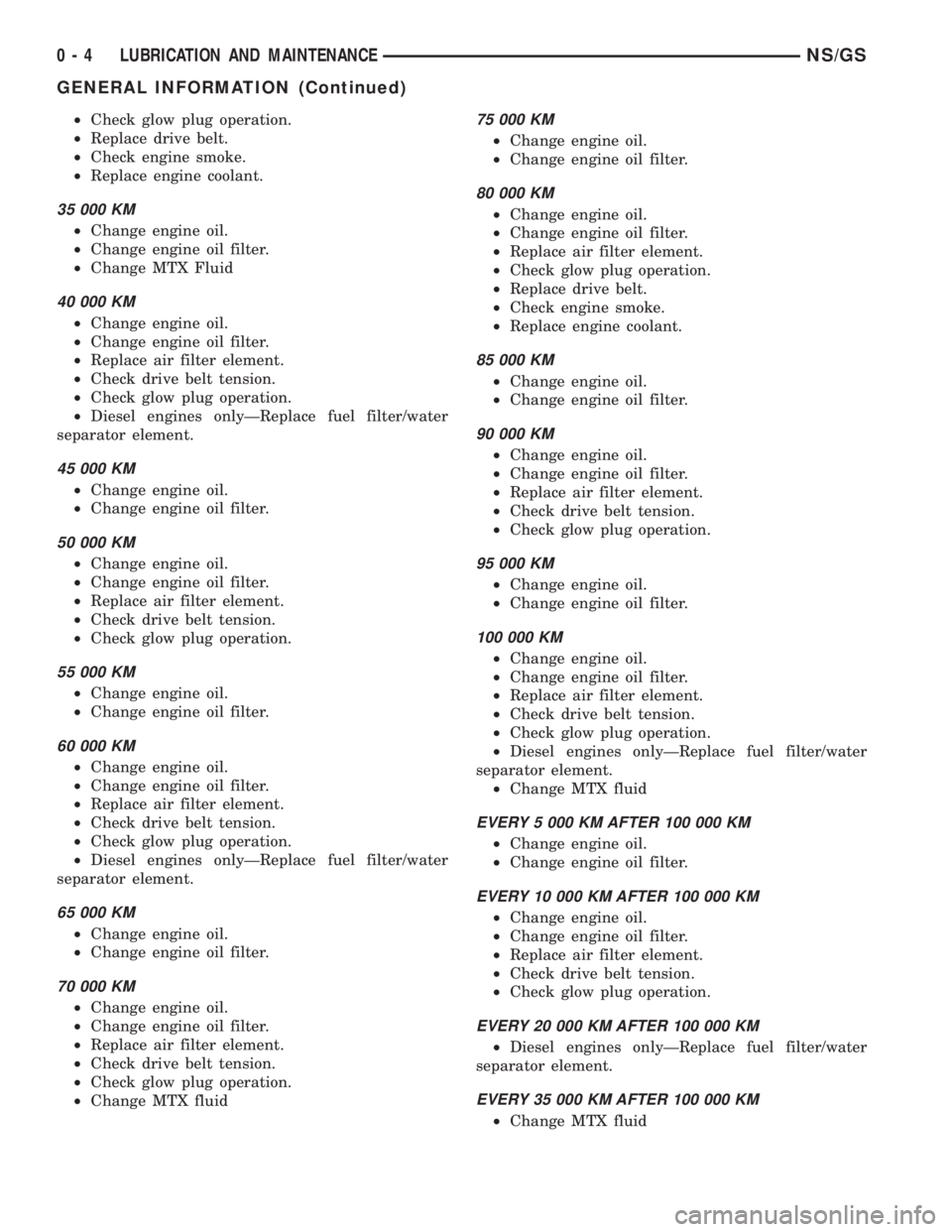
²Check glow plug operation.
²Replace drive belt.
²Check engine smoke.
²Replace engine coolant.
35 000 KM
²Change engine oil.
²Change engine oil filter.
²Change MTX Fluid
40 000 KM
²Change engine oil.
²Change engine oil filter.
²Replace air filter element.
²Check drive belt tension.
²Check glow plug operation.
²Diesel engines onlyÐReplace fuel filter/water
separator element.
45 000 KM
²Change engine oil.
²Change engine oil filter.
50 000 KM
²Change engine oil.
²Change engine oil filter.
²Replace air filter element.
²Check drive belt tension.
²Check glow plug operation.
55 000 KM
²Change engine oil.
²Change engine oil filter.
60 000 KM
²Change engine oil.
²Change engine oil filter.
²Replace air filter element.
²Check drive belt tension.
²Check glow plug operation.
²Diesel engines onlyÐReplace fuel filter/water
separator element.
65 000 KM
²Change engine oil.
²Change engine oil filter.
70 000 KM
²Change engine oil.
²Change engine oil filter.
²Replace air filter element.
²Check drive belt tension.
²Check glow plug operation.
²Change MTX fluid
75 000 KM
²Change engine oil.
²Change engine oil filter.
80 000 KM
²Change engine oil.
²Change engine oil filter.
²Replace air filter element.
²Check glow plug operation.
²Replace drive belt.
²Check engine smoke.
²Replace engine coolant.
85 000 KM
²Change engine oil.
²Change engine oil filter.
90 000 KM
²Change engine oil.
²Change engine oil filter.
²Replace air filter element.
²Check drive belt tension.
²Check glow plug operation.
95 000 KM
²Change engine oil.
²Change engine oil filter.
100 000 KM
²Change engine oil.
²Change engine oil filter.
²Replace air filter element.
²Check drive belt tension.
²Check glow plug operation.
²Diesel engines onlyÐReplace fuel filter/water
separator element.
²Change MTX fluid
EVERY 5 000 KM AFTER 100 000 KM
²Change engine oil.
²Change engine oil filter.
EVERY 10 000 KM AFTER 100 000 KM
²Change engine oil.
²Change engine oil filter.
²Replace air filter element.
²Check drive belt tension.
²Check glow plug operation.
EVERY 20 000 KM AFTER 100 000 KM
²Diesel engines onlyÐReplace fuel filter/water
separator element.
EVERY 35 000 KM AFTER 100 000 KM
²Change MTX fluid
0 - 4 LUBRICATION AND MAINTENANCENS/GS
GENERAL INFORMATION (Continued)
Page 31 of 1938
JUMP STARTING, HOISTING AND TOWING
INDEX
page
SERVICE PROCEDURES
TOWING RECOMMENDATIONS............. 5
SERVICE PROCEDURES
TOWING RECOMMENDATIONS
WARNINGS AND CAUTIONS
WARNING: DO NOT ALLOW TOWING ATTACH-
MENT DEVICES TO CONTACT THE FUEL TANK OR
LINES, FUEL LEAK CAN RESULT.
DO NOT LIFT OR TOW VEHICLE BY FRONT OR
REAR BUMPER, OR BUMPER ENERGY ABSORBER
UNITS.
DO NOT GO UNDER A LIFTED VEHICLE IF NOT
SUPPORTED PROPERLY ON SAFETY STANDS.
DO NOT ALLOW PASSENGERS TO RIDE IN A
TOWED VEHICLE.
USE A SAFETY CHAIN THAT IS INDEPENDENT
FROM THE TOWING ATTACHMENT DEVICE.
CAUTION: Do not damage brake lines, exhaust sys-
tem, shock absorbers, sway bars, or any other
under vehicle components when attaching towing
device to vehicle.
Do not attach towing device to front or rear sus-
pension components.
Do not secure vehicle to towing device by the use
of front or rear suspension or steering components.
Remove or secure loose or protruding objects
from a damaged vehicle before towing.
Refer to state and local rules and regulations
before towing a vehicle.
Do not allow weight of towed vehicle to bear on
lower fascia, air dams, or spoilers.
RECOMMENDED TOWING EQUIPMENT
To avoid damage to bumper fascia and air dams
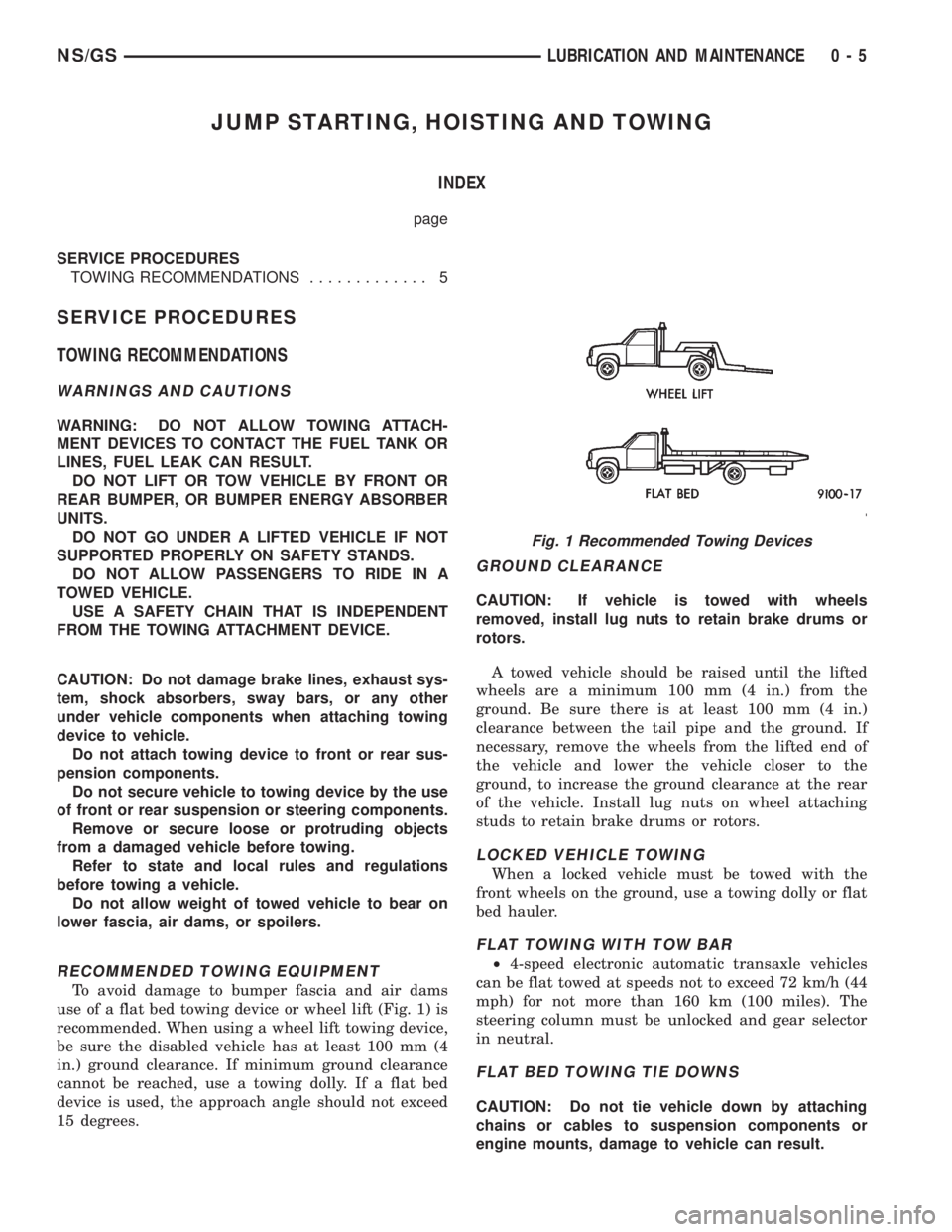
use of a flat bed towing device or wheel lift (Fig. 1) is
recommended. When using a wheel lift towing device,
be sure the disabled vehicle has at least 100 mm (4
in.) ground clearance. If minimum ground clearance
cannot be reached, use a towing dolly. If a flat bed
device is used, the approach angle should not exceed
15 degrees.
GROUND CLEARANCE
CAUTION: If vehicle is towed with wheels
removed, install lug nuts to retain brake drums or
rotors.
A towed vehicle should be raised until the lifted
wheels are a minimum 100 mm (4 in.) from the
ground. Be sure there is at least 100 mm (4 in.)
clearance between the tail pipe and the ground. If
necessary, remove the wheels from the lifted end of
the vehicle and lower the vehicle closer to the
ground, to increase the ground clearance at the rear
of the vehicle. Install lug nuts on wheel attaching
studs to retain brake drums or rotors.
LOCKED VEHICLE TOWING
When a locked vehicle must be towed with the
front wheels on the ground, use a towing dolly or flat
bed hauler.
FLAT TOWING WITH TOW BAR
²4-speed electronic automatic transaxle vehicles
can be flat towed at speeds not to exceed 72 km/h (44
mph) for not more than 160 km (100 miles). The
steering column must be unlocked and gear selector
in neutral.
FLAT BED TOWING TIE DOWNS
CAUTION: Do not tie vehicle down by attaching
chains or cables to suspension components or
engine mounts, damage to vehicle can result.
Fig. 1 Recommended Towing Devices
NS/GSLUBRICATION AND MAINTENANCE 0 - 5
Page 35 of 1938
DIAGNOSIS AND TESTING
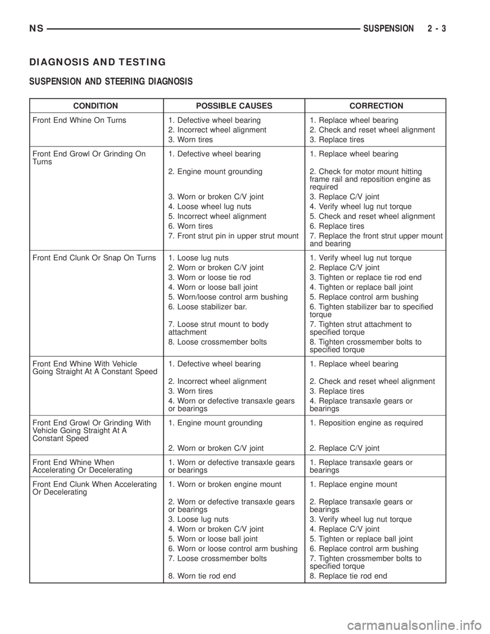
SUSPENSION AND STEERING DIAGNOSIS
CONDITION POSSIBLE CAUSES CORRECTION
Front End Whine On Turns 1. Defective wheel bearing 1. Replace wheel bearing
2. Incorrect wheel alignment 2. Check and reset wheel alignment
3. Worn tires 3. Replace tires
Front End Growl Or Grinding On
Turns1. Defective wheel bearing 1. Replace wheel bearing
2. Engine mount grounding 2. Check for motor mount hitting
frame rail and reposition engine as
required
3. Worn or broken C/V joint 3. Replace C/V joint
4. Loose wheel lug nuts 4. Verify wheel lug nut torque
5. Incorrect wheel alignment 5. Check and reset wheel alignment
6. Worn tires 6. Replace tires
7. Front strut pin in upper strut mount 7. Replace the front strut upper mount
and bearing
Front End Clunk Or Snap On Turns 1. Loose lug nuts 1. Verify wheel lug nut torque
2. Worn or broken C/V joint 2. Replace C/V joint
3. Worn or loose tie rod 3. Tighten or replace tie rod end
4. Worn or loose ball joint 4. Tighten or replace ball joint
5. Worn/loose control arm bushing 5. Replace control arm bushing
6. Loose stabilizer bar. 6. Tighten stabilizer bar to specified
torque
7. Loose strut mount to body
attachment7. Tighten strut attachment to
specified torque
8. Loose crossmember bolts 8. Tighten crossmember bolts to
specified torque
Front End Whine With Vehicle
Going Straight At A Constant Speed1. Defective wheel bearing 1. Replace wheel bearing
2. Incorrect wheel alignment 2. Check and reset wheel alignment
3. Worn tires 3. Replace tires
4. Worn or defective transaxle gears
or bearings4. Replace transaxle gears or
bearings
Front End Growl Or Grinding With
Vehicle Going Straight At A
Constant Speed1. Engine mount grounding 1. Reposition engine as required
2. Worn or broken C/V joint 2. Replace C/V joint
Front End Whine When
Accelerating Or Decelerating1. Worn or defective transaxle gears
or bearings1. Replace transaxle gears or
bearings
Front End Clunk When Accelerating
Or Decelerating1. Worn or broken engine mount 1. Replace engine mount
2. Worn or defective transaxle gears
or bearings2. Replace transaxle gears or
bearings
3. Loose lug nuts 3. Verify wheel lug nut torque
4. Worn or broken C/V joint 4. Replace C/V joint
5. Worn or loose ball joint 5. Tighten or replace ball joint
6. Worn or loose control arm bushing 6. Replace control arm bushing
7. Loose crossmember bolts 7. Tighten crossmember bolts to
specified torque
8. Worn tie rod end 8. Replace tie rod end
NSSUSPENSION 2 - 3
Page 85 of 1938
BASE BRAKE SYSTEM
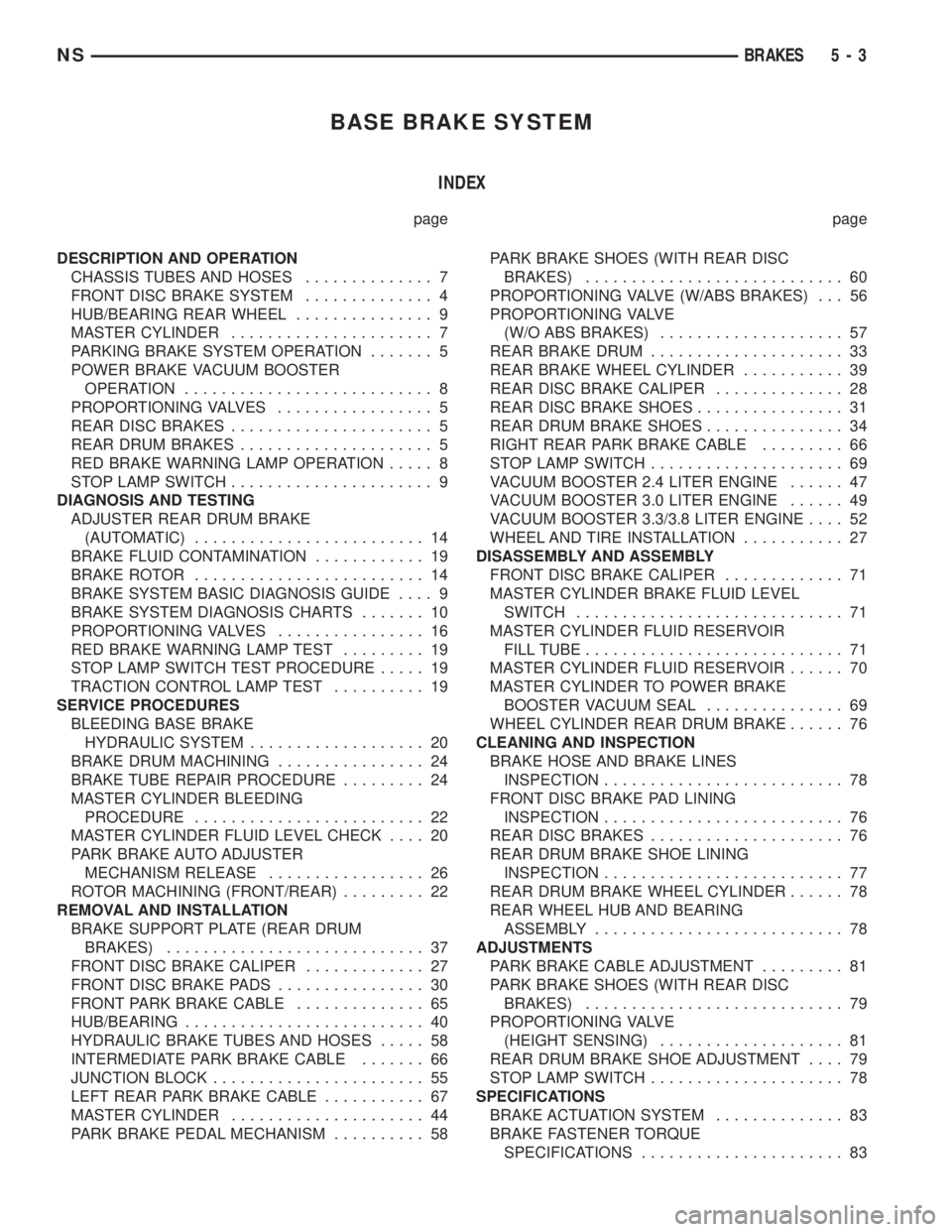
INDEX
page page
DESCRIPTION AND OPERATION
CHASSIS TUBES AND HOSES.............. 7
FRONT DISC BRAKE SYSTEM.............. 4
HUB/BEARING REAR WHEEL............... 9
MASTER CYLINDER...................... 7
PARKING BRAKE SYSTEM OPERATION....... 5
POWER BRAKE VACUUM BOOSTER
OPERATION........................... 8
PROPORTIONING VALVES................. 5
REAR DISC BRAKES...................... 5
REAR DRUM BRAKES..................... 5
RED BRAKE WARNING LAMP OPERATION..... 8
STOP LAMP SWITCH...................... 9
DIAGNOSIS AND TESTING
ADJUSTER REAR DRUM BRAKE
(AUTOMATIC)......................... 14
BRAKE FLUID CONTAMINATION............ 19
BRAKE ROTOR......................... 14
BRAKE SYSTEM BASIC DIAGNOSIS GUIDE.... 9
BRAKE SYSTEM DIAGNOSIS CHARTS....... 10
PROPORTIONING VALVES................ 16
RED BRAKE WARNING LAMP TEST......... 19
STOP LAMP SWITCH TEST PROCEDURE..... 19
TRACTION CONTROL LAMP TEST.......... 19
SERVICE PROCEDURES
BLEEDING BASE BRAKE
HYDRAULIC SYSTEM................... 20
BRAKE DRUM MACHINING................ 24
BRAKE TUBE REPAIR PROCEDURE......... 24
MASTER CYLINDER BLEEDING
PROCEDURE......................... 22
MASTER CYLINDER FLUID LEVEL CHECK.... 20
PARK BRAKE AUTO ADJUSTER
MECHANISM RELEASE................. 26
ROTOR MACHINING (FRONT/REAR)......... 22
REMOVAL AND INSTALLATION
BRAKE SUPPORT PLATE (REAR DRUM
BRAKES)............................ 37
FRONT DISC BRAKE CALIPER............. 27
FRONT DISC BRAKE PADS................ 30
FRONT PARK BRAKE CABLE.............. 65
HUB/BEARING.......................... 40
HYDRAULIC BRAKE TUBES AND HOSES..... 58
INTERMEDIATE PARK BRAKE CABLE....... 66
JUNCTION BLOCK....................... 55
LEFT REAR PARK BRAKE CABLE........... 67
MASTER CYLINDER..................... 44
PARK BRAKE PEDAL MECHANISM.......... 58PARK BRAKE SHOES (WITH REAR DISC
BRAKES)............................ 60
PROPORTIONING VALVE (W/ABS BRAKES) . . . 56
PROPORTIONING VALVE
(W/O ABS BRAKES).................... 57
REAR BRAKE DRUM..................... 33
REAR BRAKE WHEEL CYLINDER........... 39
REAR DISC BRAKE CALIPER.............. 28
REAR DISC BRAKE SHOES................ 31
REAR DRUM BRAKE SHOES............... 34
RIGHT REAR PARK BRAKE CABLE......... 66
STOP LAMP SWITCH..................... 69
VACUUM BOOSTER 2.4 LITER ENGINE...... 47
VACUUM BOOSTER 3.0 LITER ENGINE...... 49
VACUUM BOOSTER 3.3/3.8 LITER ENGINE.... 52
WHEEL AND TIRE INSTALLATION........... 27
DISASSEMBLY AND ASSEMBLY
FRONT DISC BRAKE CALIPER............. 71
MASTER CYLINDER BRAKE FLUID LEVEL
SWITCH............................. 71
MASTER CYLINDER FLUID RESERVOIR
FILL TUBE............................ 71
MASTER CYLINDER FLUID RESERVOIR...... 70
MASTER CYLINDER TO POWER BRAKE
BOOSTER VACUUM SEAL............... 69
WHEEL CYLINDER REAR DRUM BRAKE...... 76
CLEANING AND INSPECTION
BRAKE HOSE AND BRAKE LINES
INSPECTION.......................... 78
FRONT DISC BRAKE PAD LINING
INSPECTION.......................... 76
REAR DISC BRAKES..................... 76
REAR DRUM BRAKE SHOE LINING
INSPECTION.......................... 77
REAR DRUM BRAKE WHEEL CYLINDER...... 78
REAR WHEEL HUB AND BEARING
ASSEMBLY........................... 78
ADJUSTMENTS
PARK BRAKE CABLE ADJUSTMENT......... 81
PARK BRAKE SHOES (WITH REAR DISC
BRAKES)............................ 79
PROPORTIONING VALVE
(HEIGHT SENSING).................... 81
REAR DRUM BRAKE SHOE ADJUSTMENT.... 79
STOP LAMP SWITCH..................... 78
SPECIFICATIONS
BRAKE ACTUATION SYSTEM.............. 83
BRAKE FASTENER TORQUE
SPECIFICATIONS...................... 83
NSBRAKES 5 - 3
Page 90 of 1938
brakes. The secondary outlet port supplies hydraulic
pressure to the left front and right rear brakes.
POWER BRAKE VACUUM BOOSTER OPERATION
All vehicles use a 270 mm single diaphragm power
brake vacuum booster.
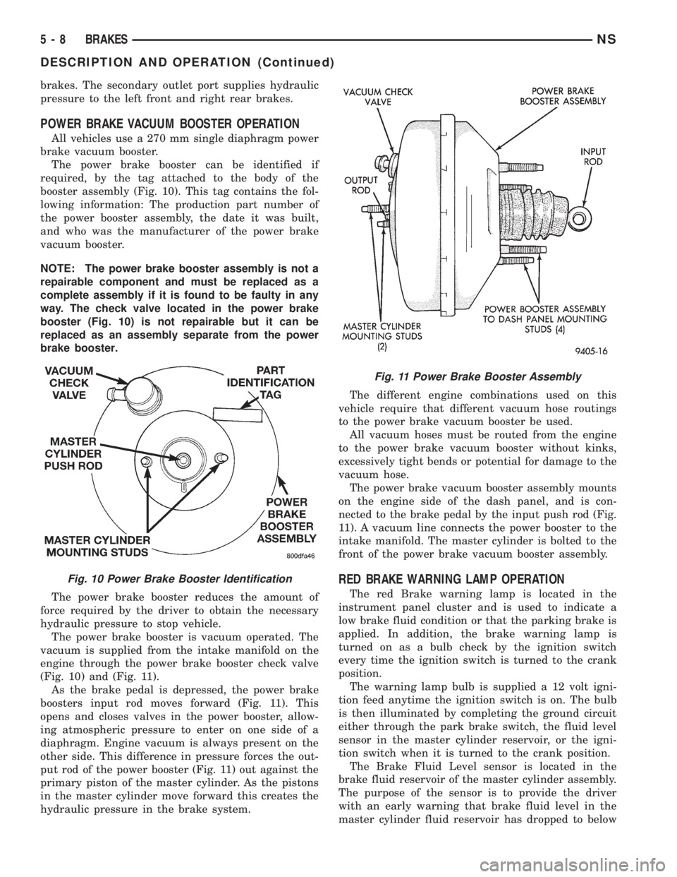
The power brake booster can be identified if
required, by the tag attached to the body of the
booster assembly (Fig. 10). This tag contains the fol-
lowing information: The production part number of
the power booster assembly, the date it was built,
and who was the manufacturer of the power brake
vacuum booster.
NOTE: The power brake booster assembly is not a
repairable component and must be replaced as a
complete assembly if it is found to be faulty in any
way. The check valve located in the power brake
booster (Fig. 10) is not repairable but it can be
replaced as an assembly separate from the power
brake booster.
The power brake booster reduces the amount of
force required by the driver to obtain the necessary
hydraulic pressure to stop vehicle.
The power brake booster is vacuum operated. The
vacuum is supplied from the intake manifold on the
engine through the power brake booster check valve
(Fig. 10) and (Fig. 11).
As the brake pedal is depressed, the power brake
boosters input rod moves forward (Fig. 11). This
opens and closes valves in the power booster, allow-
ing atmospheric pressure to enter on one side of a
diaphragm. Engine vacuum is always present on the
other side. This difference in pressure forces the out-
put rod of the power booster (Fig. 11) out against the
primary piston of the master cylinder. As the pistons
in the master cylinder move forward this creates the
hydraulic pressure in the brake system.The different engine combinations used on this
vehicle require that different vacuum hose routings
to the power brake vacuum booster be used.
All vacuum hoses must be routed from the engine
to the power brake vacuum booster without kinks,
excessively tight bends or potential for damage to the
vacuum hose.
The power brake vacuum booster assembly mounts
on the engine side of the dash panel, and is con-
nected to the brake pedal by the input push rod (Fig.
11). A vacuum line connects the power booster to the
intake manifold. The master cylinder is bolted to the
front of the power brake vacuum booster assembly.
RED BRAKE WARNING LAMP OPERATION
The red Brake warning lamp is located in the
instrument panel cluster and is used to indicate a
low brake fluid condition or that the parking brake is
applied. In addition, the brake warning lamp is
turned on as a bulb check by the ignition switch
every time the ignition switch is turned to the crank
position.
The warning lamp bulb is supplied a 12 volt igni-
tion feed anytime the ignition switch is on. The bulb
is then illuminated by completing the ground circuit
either through the park brake switch, the fluid level
sensor in the master cylinder reservoir, or the igni-
tion switch when it is turned to the crank position.
The Brake Fluid Level sensor is located in the
brake fluid reservoir of the master cylinder assembly.
The purpose of the sensor is to provide the driver
with an early warning that brake fluid level in the
master cylinder fluid reservoir has dropped to below
Fig. 10 Power Brake Booster Identification
Fig. 11 Power Brake Booster Assembly
5 - 8 BRAKESNS
DESCRIPTION AND OPERATION (Continued)
Page 91 of 1938

normal. This may indicate:(1)Abnormal loss of
brake fluid in the master cylinder fluid reservoir
resulting from a leak in the hydraulic system.(2)
Brake shoe linings which have worn to a point
requiring replacement.
As the brake fluid drops below the minimum level,
the brake fluid level sensor closes to ground the
brake warning light circuit. This will turn on the red
brake warning light. At this time, master cylinder
fluid reservoir should be checked and filled to the full
mark with DOT 3 brake fluid.If brake fluid level
has dropped below the add line in the master
cylinder fluid reservoir, the entire brake
hydraulic system should be checked for evi-
dence of a leak.
STOP LAMP SWITCH
The stop lamp switch controls operation of the
vehicles stop lamps. Also, if the vehicle is equippedwith speed control, the stop lamp switch will deacti-
vate speed control when the brake pedal is
depressed.
The stop lamp switch controls operation of the
right and left tail, stop and turn signal lamp and
CHMSL lamp, by supplying battery current to these
lamps.
The stop lamp switch controls the lamp operation
by opening and closing the electrical circuit to the
stop lamps.
HUB/BEARING REAR WHEEL
The rear hub and bearing assembly used on this
vehicle is serviceable only as a complete assembly. No
attempt should be made to disassemble a rear hub
and bearing assembly in an effort to repair it.
The rear hub and bearing assembly is attached to
the rear axle using 4 mounting bolts that are remov-
able from the back of the rear hub/bearing.
DIAGNOSIS AND TESTING
BRAKE SYSTEM BASIC DIAGNOSIS GUIDE
SYMPTOMCHART 1
MISC.
COND.CHART 2
WARNING
LIGHTCHART 3
POWER
BRAKESCHART 4
BRAKE
NOISECHART 5
WHEEL
BRAKES
Brake Warning Light On X NO NO
Excessive Pedal Travel 6 X NO O
Pedal Goes To The Floor 6 X
Stop Light On Without Brakes 3
All Brakes Drag 5
Rear Brakes Drag 2 NO NO
Grabby Brakes O X
Spongy Brake Pedal X NO
Premature Rear Brake Lockup 4 NO NO O
Excessive Pedal Effort 1 O
Rough Engine Idle NO O
Brake Chatter (Rough) NO NO X
Surge During Braking NO NO X
Noise During Braking NO NO X
Rattle Or Clunking Noise NO NO X
Pedal Pulsates During Braking NO NO X
Pull To Right Or Left NO NO X
No: Not A Possible Cause X: Most Likely Cause O: Possible Cause
NSBRAKES 5 - 9
DESCRIPTION AND OPERATION (Continued)
Page 102 of 1938
SERVICE PROCEDURES
MASTER CYLINDER FLUID LEVEL CHECK
Check master cylinder reservoir fluid level a mini-
mum of twice annually.
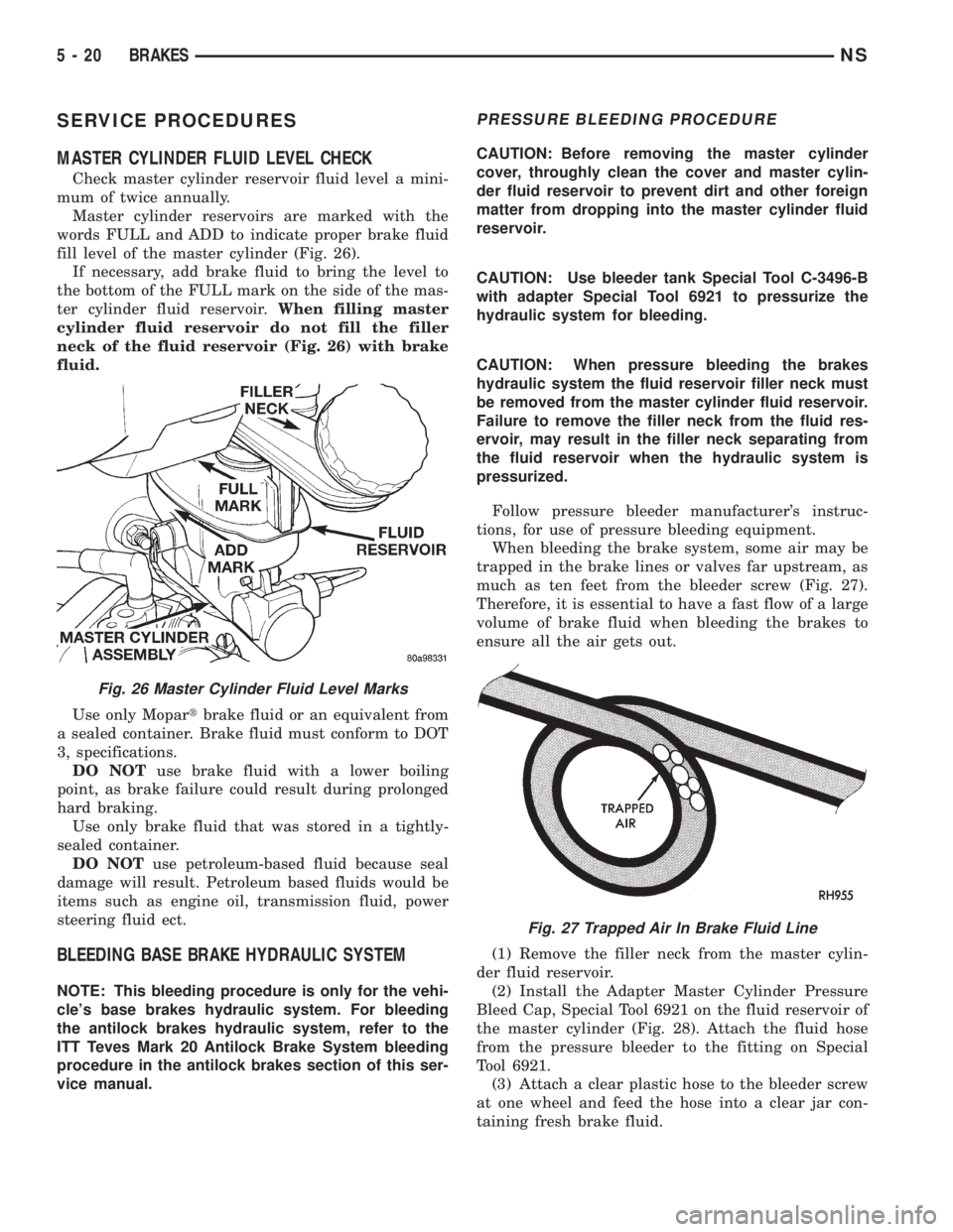
Master cylinder reservoirs are marked with the
words FULL and ADD to indicate proper brake fluid
fill level of the master cylinder (Fig. 26).
If necessary, add brake fluid to bring the level to
the bottom of the FULL mark on the side of the mas-
ter cylinder fluid reservoir.When filling master
cylinder fluid reservoir do not fill the filler
neck of the fluid reservoir (Fig. 26) with brake
fluid.
Use only Mopartbrake fluid or an equivalent from
a sealed container. Brake fluid must conform to DOT
3, specifications.
DO NOTuse brake fluid with a lower boiling
point, as brake failure could result during prolonged
hard braking.
Use only brake fluid that was stored in a tightly-
sealed container.
DO NOTuse petroleum-based fluid because seal
damage will result. Petroleum based fluids would be
items such as engine oil, transmission fluid, power
steering fluid ect.
BLEEDING BASE BRAKE HYDRAULIC SYSTEM
NOTE: This bleeding procedure is only for the vehi-
cle's base brakes hydraulic system. For bleeding
the antilock brakes hydraulic system, refer to the
ITT Teves Mark 20 Antilock Brake System bleeding
procedure in the antilock brakes section of this ser-
vice manual.
PRESSURE BLEEDING PROCEDURE
CAUTION: Before removing the master cylinder
cover, throughly clean the cover and master cylin-
der fluid reservoir to prevent dirt and other foreign
matter from dropping into the master cylinder fluid
reservoir.
CAUTION: Use bleeder tank Special Tool C-3496-B
with adapter Special Tool 6921 to pressurize the
hydraulic system for bleeding.
CAUTION: When pressure bleeding the brakes
hydraulic system the fluid reservoir filler neck must
be removed from the master cylinder fluid reservoir.
Failure to remove the filler neck from the fluid res-
ervoir, may result in the filler neck separating from
the fluid reservoir when the hydraulic system is
pressurized.
Follow pressure bleeder manufacturer's instruc-
tions, for use of pressure bleeding equipment.
When bleeding the brake system, some air may be
trapped in the brake lines or valves far upstream, as
much as ten feet from the bleeder screw (Fig. 27).
Therefore, it is essential to have a fast flow of a large
volume of brake fluid when bleeding the brakes to
ensure all the air gets out.
(1) Remove the filler neck from the master cylin-
der fluid reservoir.
(2) Install the Adapter Master Cylinder Pressure
Bleed Cap, Special Tool 6921 on the fluid reservoir of
the master cylinder (Fig. 28). Attach the fluid hose
from the pressure bleeder to the fitting on Special
Tool 6921.
(3) Attach a clear plastic hose to the bleeder screw
at one wheel and feed the hose into a clear jar con-
taining fresh brake fluid.
Fig. 26 Master Cylinder Fluid Level Marks
Fig. 27 Trapped Air In Brake Fluid Line
5 - 20 BRAKESNS
Page 126 of 1938

caliper adapter and hub/bearing are squarely seated
against the axle. Then tighten the hub/bearing
mounting bolts to a torque of 129 N´m (95 ft. lbs.).
(3) Install driveshaft in hub/bearing and on output
shaft of rear drive line module. Driveshaft is
installed by first sliding the outer joint of the drive-
shaft into the hub/bearing and then compressing the
inner joint on the driveshaft and installing it on the
output shaft the drive line module.
(4) Install rotor on hub/bearing.
(5) Carefully lower disc brake caliper and brake
shoes over rotor and onto caliper adapter by revers-
ing the removal procedure (Fig. 92).
CAUTION: When installing guide pin bolts extreme
caution should be taken not to crossthread the cal-
iper guide pin bolts.
(6) Install the disc brake caliper guide pin bolts
(Fig. 91). Tighten the guide pin bolts to a torque of
22 N´m (192 in. lbs.).
(7) Clean all foreign material off the threads of the
outer C/V joint stub shaft. Install the washer and
hub nut (Fig. 88) on the stub shaft of the outer C/V
joint.
(8) Lower vehicle.
(9) Set the park brake.This is required to keep
the driveshaft from rotating when tightening
and torquing the hub nut and driveshaft inner
joint to driveline module mounting nuts.
(10) Raise vehicle.
(11) Tighten the driveshaft inner joint to drive line
module output shaft mounting bolts (Fig. 89) to a
torque of 61 N´m (45 ft. lbs.).
(12) Tighten the outer C/V joint hub nut (Fig. 88)
to a torque of 244 N´m (180 ft. lbs.).
(13) Install the spring washer (Fig. 87) on the stub
shaft of the outer C/V joint.
(14) Install the nut retainer and cotter pin (Fig.
86) on the stub shaft of the outer C/V joint.
(15) Install the wheel speed sensor on the hub/
bearing and adapter. Install the wheel speed sensor
attaching bolt (Fig. 90). Tighten the wheel speed sen-
sor attaching bolt to a torque of 12 N´m (105 in. lbs).
(16) Install wheel and tire.
(17) Tighten the wheel mounting stud nuts in
proper sequence until all nuts are torqued to half
specification. Then repeat the tightening sequence to
the full specified torque of 129 N´m (95 ft. lbs.).
(18) Remove jackstands or lower hoist.
CAUTION: Before moving vehicle, pump the brake
pedal several times to insure the vehicle has a firm
brake pedal to adequately stop vehicle.
(19) Road test vehicle to ensure proper operation
of the brake system.MASTER CYLINDER
CAUTION: Different types of master cylinders are
used on this vehicle. Vehicles equipped with trac-
tion control use a center port master cylinder. Vehi-
cles not equipped with traction control use a
compensating port master cylinder. Be sure to ver-
ify if the vehicle is equipped with traction control
and that the correct replacement master cylinder is
used. Also, vehicles that are equipped with four
wheel disc brakes have a master with a different
size piston bore than the other master cylinders. If
a new master cylinder is being installed, be sure
the correct master cylinder is used for the type of
brake system the vehicle is equipped with.
REMOVE
CAUTION: Vacuum in the power brake booster
must be pumped down (removed) before removing
master cylinder from power brake booster. This is
necessary to prevent the power brake booster from
sucking in any contamination as the master cylin-
der is removed. This can be done simply by pump-
ing the brake pedal, with the vehicle's engine not
running, until a firm feeling brake pedal is achieved.
(1) With engine not running, pump the brake
pedal until a firm pedal is achieved (4-5 strokes).
CAUTION: Before removing the master cylinder
filler tube from the brake fluid reservoir, the filler
tube, brake fluid reservoir and master cylinder must
be thoroughly cleaned. This must be done to pre-
vent dirt particles from falling into the brake fluid
reservoir and entering the brakes hydraulic system.
(2) Thoroughly clean all surfaces of the filler neck,
brake fluid reservoir, and master cylinder. Use only a
solvent such as Mopar Brake Parts Cleaner or an
equivalent.
(3) Remove master cylinder filler tube from brake
fluid reservoir by pushing down and rotating (Fig.
97). Then remove the cap from the removed filler
tube and install it on the master cylinder reservoir.
(4) Remove vehicle wiring harness connector, from
the brake fluid level sensor, in master cylinder brake
fluid reservoir (Fig. 98).
(5) Disconnect the primary and secondary brake
tubes from the master cylinder housing (Fig. 99).
Install sealing plugs in the open brake tube outlets
on master cylinder assembly.
5 - 44 BRAKESNS
REMOVAL AND INSTALLATION (Continued)
Page 129 of 1938

CAUTION: When installing the primary and second-
ary brake tubes on master cylinder, be sure brake
tubes do not contact any other components within
the vehicle and that there is slack in the flexible
sections of the tubes. This is required due to the
movement between the ABS hydraulic control mod-
ule (HCU) and the master cylinder, when the vehicle
is in motion.
(4) Connect the primary and secondary brake
tubes to master cylinder primary and secondary
ports (Fig. 99). Brake tubes must be held securely
when tightened to control orientation of flex section.
Then fully tighten the tube nuts to a torque of 17
N´m (145 in. lbs.).
(5) Install the vehicle wiring harness connector, on
the brake fluid level sensor in the master cylinder
brake fluid reservoir (Fig. 98).
(6) Install filler tube into the master cylinder fluid
reservoir (Fig. 97).
VACUUM BOOSTER 2.4 LITER ENGINE
REMOVE
CAUTION: Reserve vacuum in the vacuum booster
must be pumped down (removed) before removing
master cylinder from vacuum booster. This is nec-
essary to prevent the vacuum booster from sucking
in any contamination as the master cylinder is
removed. This can be done simply by pumping the
brake pedal, with the vehicle's engine not running,
until a firm feeling brake pedal is achieved.
(1) With engine not running, pump brake pedal
until a firm pedal is achieved (4-5 strokes).
(2) Remove both battery cables from battery.
(3) Remove the battery thermal guard and the bat-
tery from the battery tray.
(4) Remove the air inlet resonator and hoses as an
assembly from the throttle body and air cleaner
housing (Fig. 104)
(5) If vehicle is equipped with speed control,
unplug wiring harness connector from the speed con-
trol servo. Then disconnect vacuum lines from the
speed control servo and vacuum reservoir on battery
tray.
(6) Remove bolt attaching the speed control servo
bracket to the battery tray. Slide the bracket forward
to unhook it from the battery tray and remove.
(7) Remove the 2 bolts and the nut (Fig. 105)
attaching the battery tray to the body.
(8) Remove wiring harness connector from brake
fluid level sensor in master cylinder fluid reservoir
(Fig. 106).
(9) Clean the area where the master cylinder
assembly attaches to the power brake booster. Useonly a solvent such as Mopar Brake Parts Cleaner or
an equivalent.
(10) Remove clip attaching drain hose for wiper
module to brake tube at master cylinder. Remove
Fig. 104 Air Inlet Resonator
Fig. 105 Battery Tray Mounting Locations
Fig. 106 Fluid Level Sensor Electrical Connection
NSBRAKES 5 - 47
REMOVAL AND INSTALLATION (Continued)
Page 131 of 1938

(7) Install aNEWvacuum seal on mounting flange
of master cylinder (Fig. 110).
(8) Position master cylinder on studs of vacuum
booster aligning push rod on vacuum booster with
master cylinder piston.
(9) Install the 2 nuts (Fig. 107) mounting the mas-
ter cylinder to the vacuum booster. Tighten the
mounting nuts to a torque of 25 N´m (225 in. lbs.).
(10) Install the wiper module drain hose (Fig. 107)
on the wiper module. Install the tie strap attaching
the wiper module drain hose to the brake tube at the
master cylinder.Tie strap should be loosely tight-
ened so as not to collapse the wiper module
drain hose.
(11) Install the wiring harness connector on the
brake fluid level sensor in the master cylinder fluid
reservoir (Fig. 106).
(12) Install the battery tray in the vehicle. Install
the 2 bolts and the nut (Fig. 105) attaching the bat-
tery tray. Tighten the 2 bolts and the nut to a torque
of 14 N´m (125 in lbs.).(13) If vehicle is equipped with speed control,
install the speed control servo and bracket on the
battery tray. Install and securely tighten bolt attach-
ing bracket to battery tray.
(14) If vehicle is equipped with speed control,
install the wiring harness connector on the speed
control servo. Then connect the vacuum lines onto
the speed control servo and vacuum reservoir on bat-
tery tray.
(15) Install the air inlet resonator and hoses as an
assembly on the throttle body and air cleaner hous-
ing (Fig. 104). Securely tighten the hose clamp at the
air cleaner housing and throttle body.
(16) Install the battery and the battery thermal
guard.
(17) Install the battery cables on the battery.
(18) Check the operation of the stop lamp switch
and adjust if necessary.
VACUUM BOOSTER 3.0 LITER ENGINE
REMOVE
CAUTION: Stored vacuum in the vacuum booster
must be pumped down (removed) before removing
master cylinder from power brake booster. This is
necessary to prevent the power brake booster from
sucking in any contamination as the master cylin-
der is removed. This can be done simply by pump-
ing the brake pedal, with the vehicle's engine not
running, until a firm feeling brake pedal is achieved.
(1) With engine not running, pump the brake
pedal until a firm pedal is achieved (4-5 strokes).
(2) Remove both battery cables from battery.
(3) Remove the battery thermal guard and the bat-
tery from the battery tray.
(4) Remove the air inlet resonator and hoses as an
assembly from the throttle body and air cleaner
housing (Fig. 111)
(5) If vehicle is equipped with speed control,
unplug wiring harness connector from the speed con-
trol servo. Then disconnect vacuum lines from the
speed control servo and vacuum reservoir on battery
tray.
(6) Remove bolt attaching the speed control servo
bracket to the battery tray. Slide the bracket forward
to unhook it from the battery tray and remove.
(7) Remove the 2 bolts and the nut (Fig. 112)
attaching the battery tray to the body of the vehicle.
(8) Remove wiring harness connector from brake
fluid level sensor in master cylinder fluid reservoir
(Fig. 113).
(9) Clean the area where the master cylinder
assembly attaches to the power brake booster. Use
only a solvent such as Mopar Brake Parts Cleaner or
an equivalent.
Fig. 109 Retaining Clip Installed On Brake Pedal Pin
Fig. 110 Vacuum Seal Installed On Master Cylinder
NSBRAKES 5 - 49
REMOVAL AND INSTALLATION (Continued)