engine CHRYSLER VOYAGER 1996 Owner's Guide
[x] Cancel search | Manufacturer: CHRYSLER, Model Year: 1996, Model line: VOYAGER, Model: CHRYSLER VOYAGER 1996Pages: 1938, PDF Size: 55.84 MB
Page 134 of 1938

(11) Install the wiring harness connector on the
brake fluid level sensor in the master cylinder fluid
reservoir (Fig. 113).
(12) Install the battery tray in the vehicle. Install
the 2 bolts and the nut (Fig. 112) attaching the bat-
tery tray to the vehicle. Tighten the 2 bolts and the
nut to a torque of 14 N´m (125 in lbs.).
(13) If vehicle is equipped with speed control,
install the speed control servo and bracket on the
battery tray. Install and securely tighten bolt attach-
ing bracket to battery tray.
(14) If vehicle is equipped with speed control,
install the wiring harness connector on the speed
control servo. Then connect the vacuum lines onto
the speed control servo and vacuum reservoir on bat-
tery tray.
(15) Install the air inlet resonator and hoses as an
assembly on the throttle body and air cleaner hous-
ing (Fig. 111). Securely tighten the hose clamp at the
air cleaner housing and throttle body.
(16) Install the battery and the battery thermal
guard.
(17) Install the battery cables on the battery.
(18) Check the operation of the stop lamp switch
and adjust if necessary.
VACUUM BOOSTER 3.3/3.8 LITER ENGINE
REMOVE
CAUTION: Reserve vacuum in the vacuum booster
must be pumped down (removed) before removing
master cylinder from vacuum booster. This is nec-
essary to prevent the vacuum booster from sucking
in any contamination as the master cylinder is
removed. This can be done simply by pumping the
brake pedal, with the vehicle's engine not running,
until a firm feeling brake pedal is achieved.
(1) With engine not running, pump the brake
pedal until a firm pedal is achieved (4-5 strokes).
(2) Remove both battery cables from battery.
(3) Remove the battery thermal guard and the bat-
tery from the battery tray.
(4) Remove the air inlet resonator and hoses as an
assembly from the throttle body and air cleaner
housing (Fig. 118)
(5) If vehicle is equipped with speed control,
unplug wiring harness connector from the speed con-
trol servo. Then disconnect vacuum lines from the
speed control servo and vacuum reservoir on battery
tray.
(6) Remove bolt attaching the speed control servo
bracket to the battery tray. Slide the bracket forward
to unhook it from the battery tray and remove.
(7) Remove the 2 bolts and the nut (Fig. 119)
attaching the battery tray to the body of the vehicle.(8) Remove the wiring harness connector (Fig. 120)
from the EGR valve transducer.
(9) Remove wiring harness connectors from throt-
tle position sensor and AIS motor on throttle body
(Fig. 121).
(10) Remove the 2 bolts (Fig. 122) attaching the
throttle body to the intake manifold and the clip (Fig.
122) attaching the wiring harness to the throttle
cable bracket. Then remove the throttle body and
throttle cable bracket as an assembly from the intake
manifold.
(11) Remove wiring harness connector from brake
fluid level sensor in master cylinder fluid reservoir
(Fig. 123).
(12) Clean the area where the master cylinder
assembly attaches to the power brake booster. Use
Fig. 118 Air Inlet Resonator
Fig. 119 Battery Tray Mounting Locations
5 - 52 BRAKESNS
REMOVAL AND INSTALLATION (Continued)
Page 160 of 1938
REAR DRUM BRAKE WHEEL CYLINDER
With brake drums removed, inspect the wheel cyl-
inder boots for evidence of a brake fluid leak. Visu-
ally check the boots for cuts, tears, or heat cracks. If
any of these conditions exist, the wheel cylinders
should be completely cleaned, inspected and new
parts installed.
If a wheel cylinder is leaking and the brake lining
material is saturated with brake fluid, the brake
shoes must be replaced.
BRAKE HOSE AND BRAKE LINES INSPECTION
Flexible rubber hose is used at both front brakes
and at the rear axle. Inspection of brake hoses
should be performed whenever the brake system is
serviced and every 7,500 miles or 12 months, which-
ever comes first (every engine oil change). Inspect
hydraulic brake hoses for surface cracking, scuffing,
or worn spots. If the fabric casing of the rubber hose
becomes exposed due to cracks or abrasions in the
rubber hose cover, the hose should be replaced imme-
diately. Eventual deterioration of the hose can take
place with possible burst failure. Faulty installation
can cause twisting, resulting in wheel, tire, or chassis
interference.
The steel brake tubing should be inspected period-
ically for evidence of physical damage or contact with
moving or hot components.
The flexible brake tube sections used on this vehi-
cle in the primary and secondary tubes from the
master cylinder to the ABS hydraulic control unit
connections and the chassis brake tubes between the
hydraulic control unit and the proportioning valve
must also be inspected. This flexible tubing must be
inspected for kinks, fraying and its contact with
other components of the vehicle or contact with the
body of the vehicle.
REAR WHEEL HUB AND BEARING ASSEMBLY
The rear hub and bearing assembly is designed for
the life of the vehicle and should require no mainte-
nance. The following procedure may be used for eval-
uation of bearing condition.
With wheel and brake drum removed, rotate
flanged outer ring of hub. Excessive roughness, lat-
eral play or resistance to rotation may indicate dirt
intrusion or bearing failure. If the rear wheel bear-
ings exhibit these conditions during inspection, the
hub and bearing assembly should be replaced.
Damaged bearing seals and resulting excessive
grease loss may also require bearing replacement.
Moderate grease loss from bearing is considered nor-
mal and should not require replacement of the hub
and bearing assembly.
ADJUSTMENTS
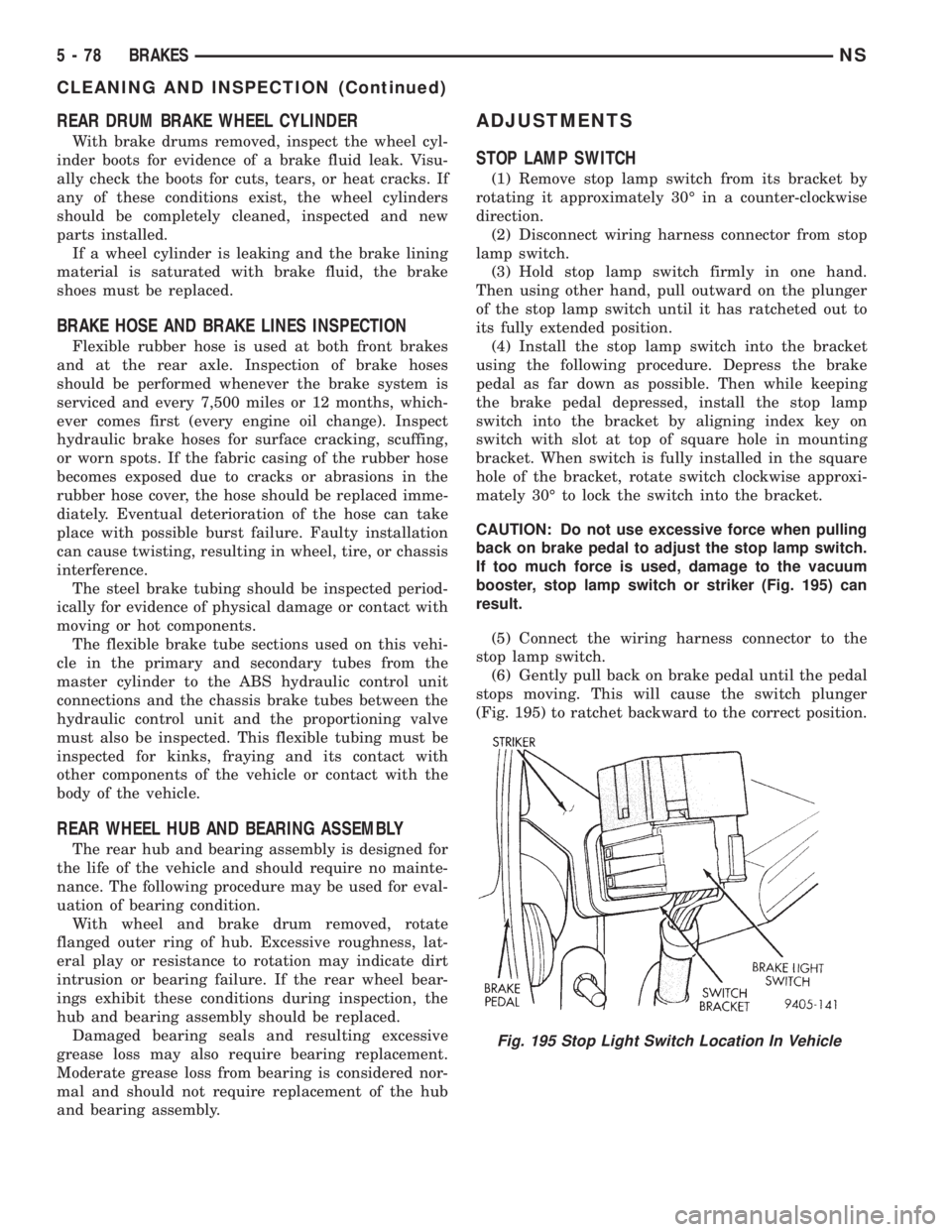
STOP LAMP SWITCH
(1) Remove stop lamp switch from its bracket by
rotating it approximately 30É in a counter-clockwise
direction.
(2) Disconnect wiring harness connector from stop
lamp switch.
(3) Hold stop lamp switch firmly in one hand.
Then using other hand, pull outward on the plunger
of the stop lamp switch until it has ratcheted out to
its fully extended position.
(4) Install the stop lamp switch into the bracket
using the following procedure. Depress the brake
pedal as far down as possible. Then while keeping
the brake pedal depressed, install the stop lamp
switch into the bracket by aligning index key on
switch with slot at top of square hole in mounting
bracket. When switch is fully installed in the square
hole of the bracket, rotate switch clockwise approxi-
mately 30É to lock the switch into the bracket.
CAUTION: Do not use excessive force when pulling
back on brake pedal to adjust the stop lamp switch.
If too much force is used, damage to the vacuum
booster, stop lamp switch or striker (Fig. 195) can
result.
(5) Connect the wiring harness connector to the
stop lamp switch.
(6) Gently pull back on brake pedal until the pedal
stops moving. This will cause the switch plunger
(Fig. 195) to ratchet backward to the correct position.
Fig. 195 Stop Light Switch Location In Vehicle
5 - 78 BRAKESNS
CLEANING AND INSPECTION (Continued)
Page 164 of 1938
(13) Lower the vehicle to the ground.Be sure
that the suspension is supporting the full
weight of the vehicle.
(14) Tighten the spring to front hanger pivot bolts
to a torque of 156 N´m (115 ft. lbs.).
(15) Tighten the shock absorber mounting bolts to
a torque of 101 N´m (75 ft. lbs.).
(16) Tighten the track bar mounting bolt to a
torque of 95 N´m (70 ft. lbs.).
(17) Road test vehicle to ensure that the prema-
ture rear wheel lockup condition has been corrected.
SPECIFICATIONS
BRAKE FLUID
The brake fluid used in this vehicle must conform
to DOT 3 specifications and SAE J1703 standards.No other type of brake fluid is recommended or
approved for usage in the vehicle brake system. Use
only Mopar brake fluid or an equivalent from a
tightly sealed container.
CAUTION: Never use reclaimed brake fluid or fluid
from an container which has been left open. An
open container will absorb moisture from the air
and contaminate the fluid.
CAUTION: Never use any type of a petroleum-
based fluid in the brake hydraulic system. Use of
such type fluids will result in seal damage of the
vehicle brake hydraulic system causing a failure of
the vehicle brake system. Petroleum based fluids
would be items such as engine oil, transmission
fluid, power steering fluid ect.
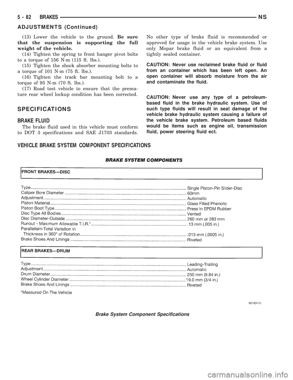
VEHICLE BRAKE SYSTEM COMPONENT SPECIFICATIONS
Brake System Component Specifications
5 - 82 BRAKESNS
ADJUSTMENTS (Continued)
Page 171 of 1938
fluid accumulators temporarily store brake fluid that
is decayed from the wheel brakes during an ABS
cycle. This stored brake fluid is then used by the
pump in the HCU to provide build pressure for the
brake hydraulic system.
Additionally on vehicles that are equipped with
only ABS (non-traction control vehicles) there is a
mini brake fluid accumulator on the secondary
hydraulic circuit which protects the master cylinder's
seals during an ABS stop. There is also a noise
damping chamber on the primary hydraulic circuit.
On ABS equipped vehicles with traction control, in
addition to the brake fluid accumulators there are
also two noise damping chambers in the HCU.
HCU PUMP/MOTOR
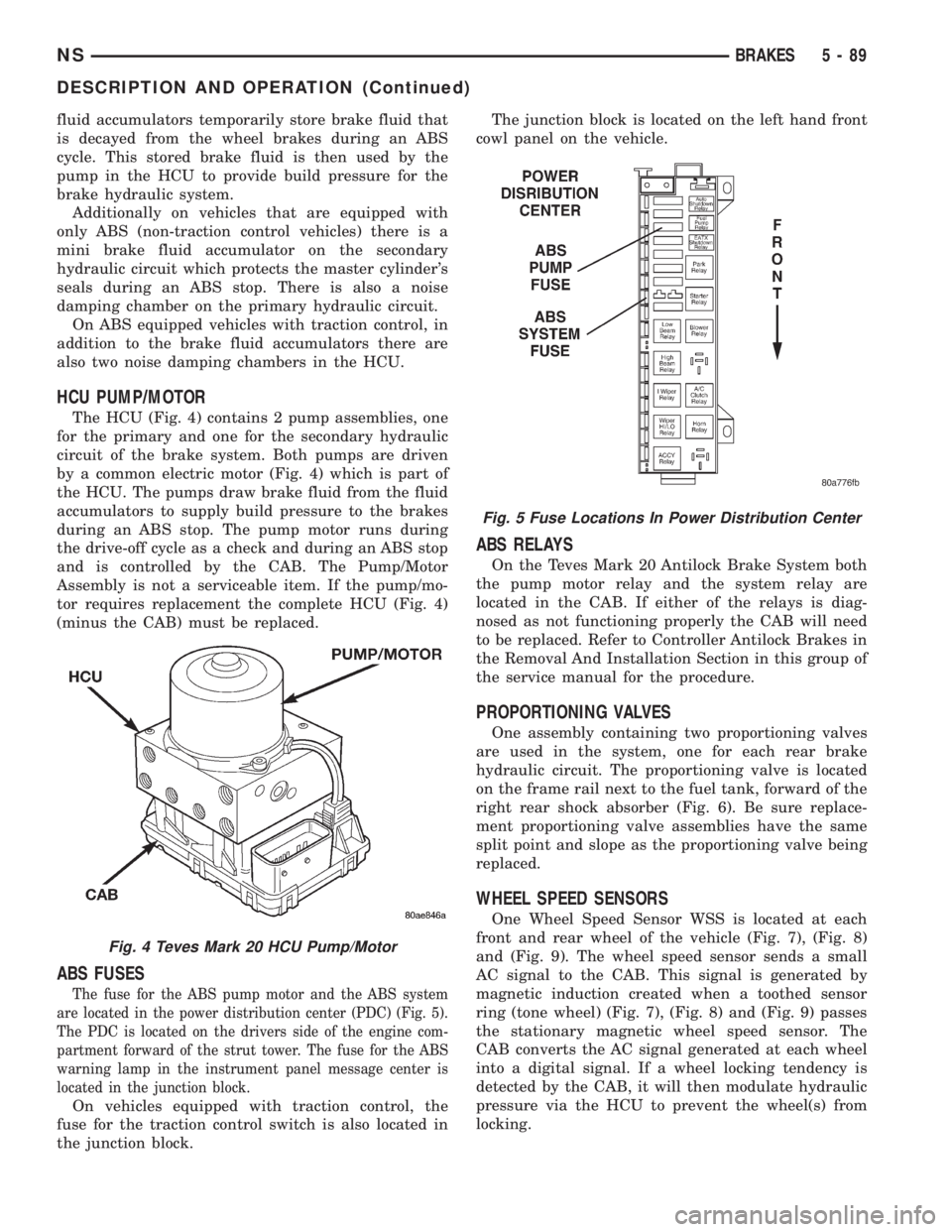
The HCU (Fig. 4) contains 2 pump assemblies, one
for the primary and one for the secondary hydraulic
circuit of the brake system. Both pumps are driven
by a common electric motor (Fig. 4) which is part of
the HCU. The pumps draw brake fluid from the fluid
accumulators to supply build pressure to the brakes
during an ABS stop. The pump motor runs during
the drive-off cycle as a check and during an ABS stop
and is controlled by the CAB. The Pump/Motor
Assembly is not a serviceable item. If the pump/mo-
tor requires replacement the complete HCU (Fig. 4)
(minus the CAB) must be replaced.
ABS FUSES
The fuse for the ABS pump motor and the ABS system
are located in the power distribution center (PDC) (Fig. 5).
The PDC is located on the drivers side of the engine com-
partment forward of the strut tower. The fuse for the ABS
warning lamp in the instrument panel message center is
located in the junction block.
On vehicles equipped with traction control, the
fuse for the traction control switch is also located in
the junction block.The junction block is located on the left hand front
cowl panel on the vehicle.
ABS RELAYS
On the Teves Mark 20 Antilock Brake System both
the pump motor relay and the system relay are
located in the CAB. If either of the relays is diag-
nosed as not functioning properly the CAB will need
to be replaced. Refer to Controller Antilock Brakes in
the Removal And Installation Section in this group of
the service manual for the procedure.
PROPORTIONING VALVES
One assembly containing two proportioning valves
are used in the system, one for each rear brake
hydraulic circuit. The proportioning valve is located
on the frame rail next to the fuel tank, forward of the
right rear shock absorber (Fig. 6). Be sure replace-
ment proportioning valve assemblies have the same
split point and slope as the proportioning valve being
replaced.
WHEEL SPEED SENSORS
One Wheel Speed Sensor WSS is located at each
front and rear wheel of the vehicle (Fig. 7), (Fig. 8)
and (Fig. 9). The wheel speed sensor sends a small
AC signal to the CAB. This signal is generated by
magnetic induction created when a toothed sensor
ring (tone wheel) (Fig. 7), (Fig. 8) and (Fig. 9) passes
the stationary magnetic wheel speed sensor. The
CAB converts the AC signal generated at each wheel
into a digital signal. If a wheel locking tendency is
detected by the CAB, it will then modulate hydraulic
pressure via the HCU to prevent the wheel(s) from
locking.
Fig. 4 Teves Mark 20 HCU Pump/Motor
Fig. 5 Fuse Locations In Power Distribution Center
NSBRAKES 5 - 89
DESCRIPTION AND OPERATION (Continued)
Page 198 of 1938
BRAKE PEDAL TORQUE SHAFT ASSEMBLY
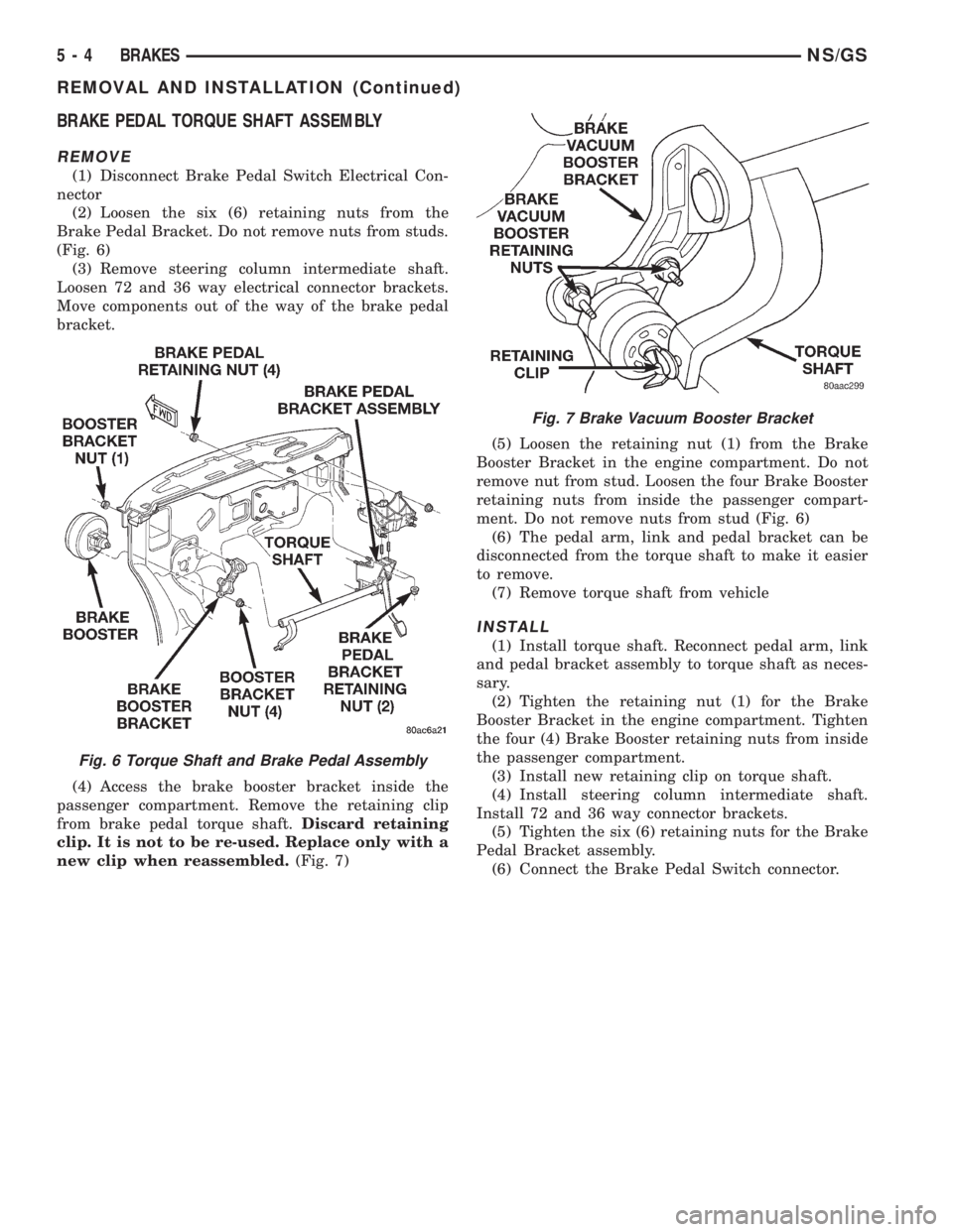
REMOVE
(1) Disconnect Brake Pedal Switch Electrical Con-
nector
(2) Loosen the six (6) retaining nuts from the
Brake Pedal Bracket. Do not remove nuts from studs.
(Fig. 6)
(3) Remove steering column intermediate shaft.
Loosen 72 and 36 way electrical connector brackets.
Move components out of the way of the brake pedal
bracket.
(4) Access the brake booster bracket inside the
passenger compartment. Remove the retaining clip
from brake pedal torque shaft.Discard retaining
clip. It is not to be re-used. Replace only with a
new clip when reassembled.(Fig. 7)(5) Loosen the retaining nut (1) from the Brake
Booster Bracket in the engine compartment. Do not
remove nut from stud. Loosen the four Brake Booster
retaining nuts from inside the passenger compart-
ment. Do not remove nuts from stud (Fig. 6)
(6) The pedal arm, link and pedal bracket can be
disconnected from the torque shaft to make it easier
to remove.
(7) Remove torque shaft from vehicle
INSTALL
(1) Install torque shaft. Reconnect pedal arm, link
and pedal bracket assembly to torque shaft as neces-
sary.
(2) Tighten the retaining nut (1) for the Brake
Booster Bracket in the engine compartment. Tighten
the four (4) Brake Booster retaining nuts from inside
the passenger compartment.
(3) Install new retaining clip on torque shaft.
(4) Install steering column intermediate shaft.
Install 72 and 36 way connector brackets.
(5) Tighten the six (6) retaining nuts for the Brake
Pedal Bracket assembly.
(6) Connect the Brake Pedal Switch connector.
Fig. 6 Torque Shaft and Brake Pedal Assembly
Fig. 7 Brake Vacuum Booster Bracket
5 - 4 BRAKESNS/GS
REMOVAL AND INSTALLATION (Continued)
Page 199 of 1938
CLUTCH
CONTENTS
page page
GENERAL INFORMATION
CLUTCH COMPONENTS.................. 1
CLUTCH DISC AND COVER APPLICATION . . . 3
CLUTCH REPLACEMENT................. 3
DESCRIPTION AND OPERATION
CLUTCH PEDAL POSITION SWITCH........ 4
CLUTCH RELEASE SYSTEM.............. 4
DIAGNOSIS AND TESTING
CLASH±INTO±REVERSE
COMPLAINTS........................ 8
CLUTCH CHATTER COMPLAINTS.......... 8
CLUTCH COVER AND DISC RUNOUT....... 8
CLUTCH DIAGNOSIS.................... 6
CLUTCH PEDAL POSITION SWITCH........ 4
DRIVE PLATE MISALIGNMENT............ 7
REMOVAL AND INSTALLATION
CLUTCH ASSEMBLY (2.5L DIESEL)....... 13
CLUTCH CABLE SYSTEM Ð LHD.......... 8
CLUTCH PEDAL POSITION SWITCH....... 10CLUTCH RELEASE BEARING AND FORK . . . 14
HYDRAULIC CLUTCH LINKAGE SYSTEM Ð
RHD ............................... 11
MASTER CYLINDER SYSTEM
Ð RHD ............................ 12
MODULAR CLUTCH ASSEMBLY (2.0L AND
2.4L GASOLINE)..................... 13
QUICK CONNECT COUPLING
Ð RHD ............................ 12
SLAVE CYLINDER ASSEMBLY
Ð RHD ............................ 12
CLEANING AND INSPECTION
CLEANING PRECAUTIONS............... 15
CLUTCH CONTAMINATION.............. 15
ADJUSTMENTS
CLUTCH CABLE Ð LHD................ 16
CLUTCH PEDAL POSITION SWITCH....... 16
SPECIFICATIONS
CLUTCH TIGHTENING REFERENCE........ 16
GENERAL INFORMATION
CLUTCH COMPONENTS
The clutch used in the 2.0 liter and 2.4 liter gaso-
line engine is a single, dry-disc modular clutch
assembly. The modular clutch assembly combines the
pressure plate cover, pressure plate, disc, and fly-
wheel into one unit. The unit rides on the input shaft
of the transmission and is bolted to the drive plate
mounted on the rear of the crankshaft. The clutch
used in the 2.5 liter diesel engine is a conventional
clutch and pressure plate arrangement.
CLUTCH CABLE AND PEDAL Ð LHD
The clutch cable has a unique self-adjuster mecha-
nism built into the cable which compensates for
clutch disc wear. The cable requires no maintenance
or lubrication. There are no serviceable components
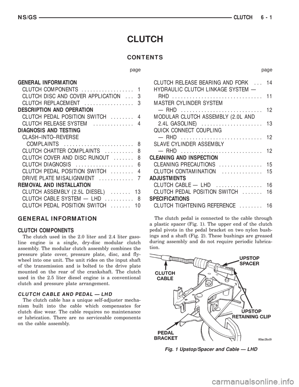
on the cable assembly.The clutch pedal is connected to the cable through
a plastic spacer (Fig. 1). The upper end of the clutch
pedal pivots in the pedal bracket on two nylon bush-
ings and a shaft (Fig. 2). These bushings are greased
during assembly and do not require periodic lubrica-
tion.
Fig. 1 Upstop/Spacer and Cable Ð LHD
NS/GSCLUTCH 6 - 1
Page 201 of 1938
CLUTCH DISC AND COVER APPLICATION
The 2.0 liter and 2.4 liter gasoline engines use a
240 mm (9.5 in.) modular clutch assembly. The 2.5
liter diesel engine uses a 240 mm (9.5 in.) standard
clutch and pressure plate arrangement. Although the
clutches are the same size they do not interchange.
CLUTCH REPLACEMENT
The transaxle must be removed to service the
clutch assembly, fork, or bearing.
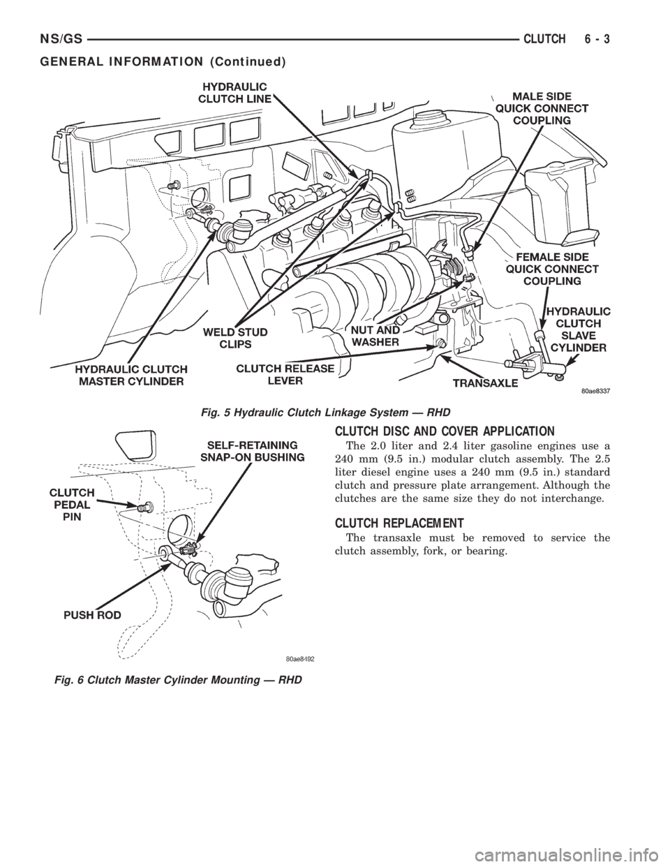
Fig. 5 Hydraulic Clutch Linkage System Ð RHD
Fig. 6 Clutch Master Cylinder Mounting Ð RHD
NS/GSCLUTCH 6 - 3
GENERAL INFORMATION (Continued)
Page 202 of 1938
DESCRIPTION AND OPERATION
CLUTCH RELEASE SYSTEM
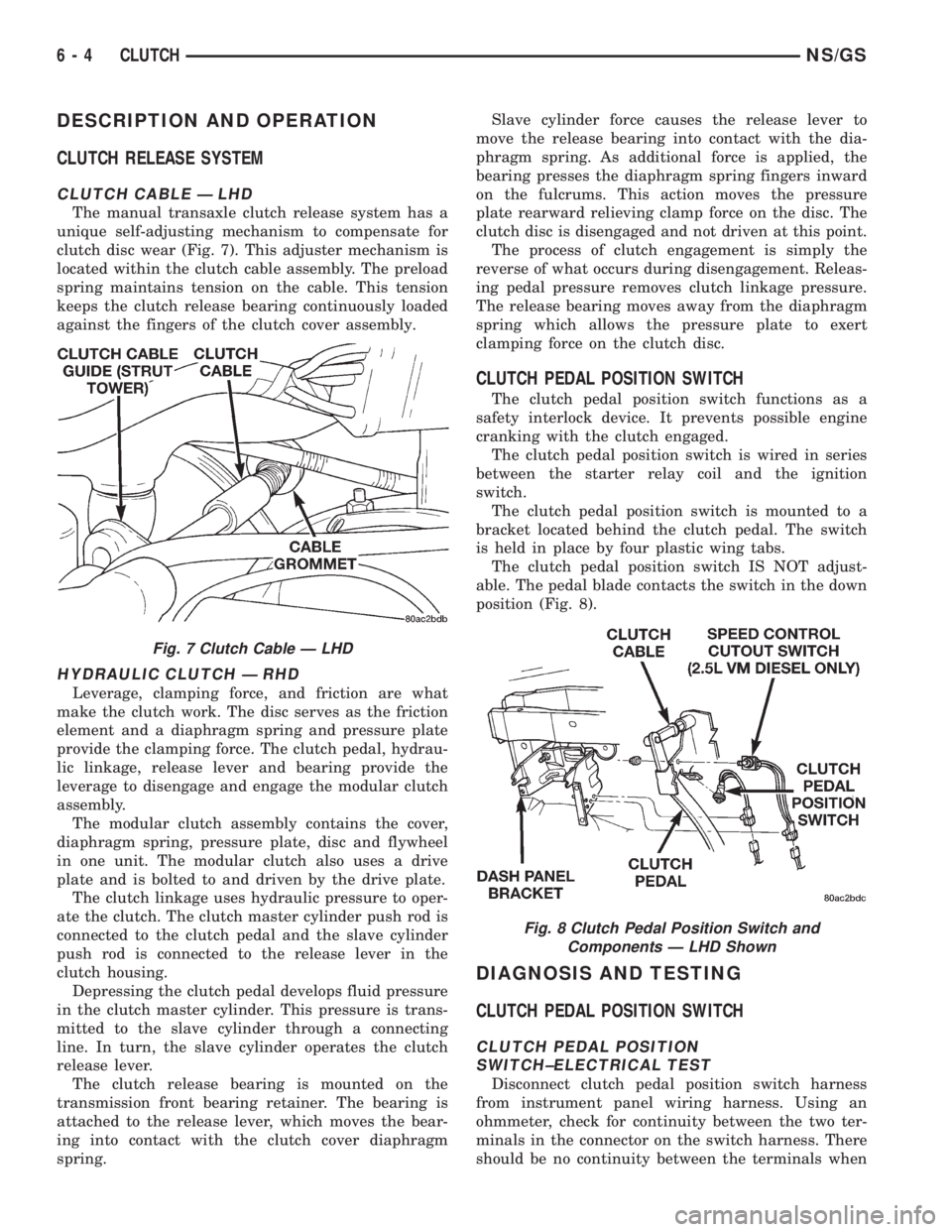
CLUTCH CABLE Ð LHD
The manual transaxle clutch release system has a
unique self-adjusting mechanism to compensate for
clutch disc wear (Fig. 7). This adjuster mechanism is
located within the clutch cable assembly. The preload
spring maintains tension on the cable. This tension
keeps the clutch release bearing continuously loaded
against the fingers of the clutch cover assembly.
HYDRAULIC CLUTCH Ð RHD
Leverage, clamping force, and friction are what
make the clutch work. The disc serves as the friction
element and a diaphragm spring and pressure plate
provide the clamping force. The clutch pedal, hydrau-
lic linkage, release lever and bearing provide the
leverage to disengage and engage the modular clutch
assembly.
The modular clutch assembly contains the cover,
diaphragm spring, pressure plate, disc and flywheel
in one unit. The modular clutch also uses a drive
plate and is bolted to and driven by the drive plate.
The clutch linkage uses hydraulic pressure to oper-
ate the clutch. The clutch master cylinder push rod is
connected to the clutch pedal and the slave cylinder
push rod is connected to the release lever in the
clutch housing.
Depressing the clutch pedal develops fluid pressure
in the clutch master cylinder. This pressure is trans-
mitted to the slave cylinder through a connecting
line. In turn, the slave cylinder operates the clutch
release lever.
The clutch release bearing is mounted on the
transmission front bearing retainer. The bearing is
attached to the release lever, which moves the bear-
ing into contact with the clutch cover diaphragm
spring.Slave cylinder force causes the release lever to
move the release bearing into contact with the dia-
phragm spring. As additional force is applied, the
bearing presses the diaphragm spring fingers inward
on the fulcrums. This action moves the pressure
plate rearward relieving clamp force on the disc. The
clutch disc is disengaged and not driven at this point.
The process of clutch engagement is simply the
reverse of what occurs during disengagement. Releas-
ing pedal pressure removes clutch linkage pressure.
The release bearing moves away from the diaphragm
spring which allows the pressure plate to exert
clamping force on the clutch disc.
CLUTCH PEDAL POSITION SWITCH
The clutch pedal position switch functions as a
safety interlock device. It prevents possible engine
cranking with the clutch engaged.
The clutch pedal position switch is wired in series
between the starter relay coil and the ignition
switch.
The clutch pedal position switch is mounted to a
bracket located behind the clutch pedal. The switch
is held in place by four plastic wing tabs.
The clutch pedal position switch IS NOT adjust-
able. The pedal blade contacts the switch in the down
position (Fig. 8).
DIAGNOSIS AND TESTING
CLUTCH PEDAL POSITION SWITCH
CLUTCH PEDAL POSITION
SWITCH±ELECTRICAL TEST
Disconnect clutch pedal position switch harness
from instrument panel wiring harness. Using an
ohmmeter, check for continuity between the two ter-
minals in the connector on the switch harness. There
should be no continuity between the terminals when
Fig. 7 Clutch Cable Ð LHD
Fig. 8 Clutch Pedal Position Switch and
Components Ð LHD Shown
6 - 4 CLUTCHNS/GS
Page 203 of 1938
the switch is in its normal (fully extended) position.
When the switch is depressed more than 1.25 mm
(0.050), the ohmmeter should show continuity (zero
ohms).
If ohmmeter readings do not fall within these
ranges, the switch is defective, and must be replaced.
CLUTCH PEDAL POSITION
SWITCH±MECHANICAL TEST
With the park brake set and the vehicleIN NEU-
TRAL,turn the key to the start position. The vehicle
should not crank. If the vehicle cranks, the switch is
defective (shorted out) and must be replaced. If the
vehicle does not crank proceed to the next step.
WARNING: BEFORE PERFORMING THIS STEP, BE
SURE THAT THE AREA IN FRONT OF THE VEHICLE
IS CLEAR OF OBSTRUCTIONS AND PEOPLE. VEHI-
CLE MAY MOVE WHEN PERFORMING THIS TEST.With the park brake set and the vehicleIN GEAR,
turn the key to the start position and hold it there.
Slowly depress the clutch pedal and feel for any
vehicle motion when the starter is energized. If there
is no motion the switch is working properly.
If motion is felt, check to see if the switch is mak-
ing contact when the pedal is between 25 mm (1.0
in.) and 6 mm (0.25 in.) from the floor. If this condi-
tion is met, then the problem is either the clutch or
the clutch actuation system (See ªClutch Will Not
Disengage Properlyº). If this condition is not met,
then the switch mounting tab on the brake bracket is
bent, and the brake bracket must be replaced.
If vehicle will not crank, even with clutch pedal
pressed to the floor, refer to ªService Diagnosis-
Clutch Pedal Position Switchº chart in this section.
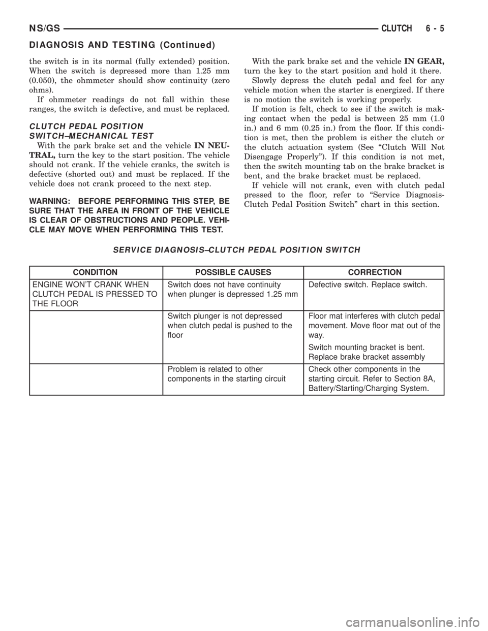
SERVICE DIAGNOSIS±CLUTCH PEDAL POSITION SWITCH
CONDITION POSSIBLE CAUSES CORRECTION
ENGINE WON'T CRANK WHEN
CLUTCH PEDAL IS PRESSED TO
THE FLOORSwitch does not have continuity
when plunger is depressed 1.25 mmDefective switch. Replace switch.
Switch plunger is not depressed
when clutch pedal is pushed to the
floorFloor mat interferes with clutch pedal
movement. Move floor mat out of the
way.
Switch mounting bracket is bent.
Replace brake bracket assembly
Problem is related to other
components in the starting circuitCheck other components in the
starting circuit. Refer to Section 8A,
Battery/Starting/Charging System.
NS/GSCLUTCH 6 - 5
DIAGNOSIS AND TESTING (Continued)
Page 204 of 1938
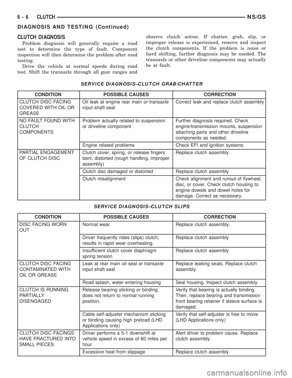
CLUTCH DIAGNOSIS
Problem diagnosis will generally require a road
test to determine the type of fault. Component
inspection will then determine the problem after road
testing.
Drive the vehicle at normal speeds during road
test. Shift the transaxle through all gear ranges andobserve clutch action. If chatter, grab, slip, or
improper release is experienced, remove and inspect
the clutch components. If the problem is noise or
hard shifting, further diagnosis may be needed. The
transaxle or other driveline components may actually
be at fault.
SERVICE DIAGNOSIS±CLUTCH GRAB/CHATTER
CONDITION POSSIBLE CAUSES CORRECTION
CLUTCH DISC FACING
COVERED WITH OIL OR
GREASEOil leak at engine rear main or transaxle
input shaft sealCorrect leak and replace clutch assembly
NO FAULT FOUND WITH
CLUTCH
COMPONENTSProblem actually related to suspension
or driveline componentFurther diagnosis required. Check
engine/transmission mounts, suspension
attaching parts and other driveline
components as needed.
Engine related problems Check EFI and ignition systems
PARTIAL ENGAGEMENT
OF CLUTCH DISCClutch cover, spring, or release fingers
bent, distorted (rough handling, improper
assembly)Replace clutch assembly
Clutch disc damaged or distorted Replace clutch assembly
Clutch misalignment Check alignment and runout of flywheel,
disc, or cover. Check clutch housing to
engine dowels and dowel holes for
damage. Correct as necessary.
SERVICE DIAGNOSIS±CLUTCH SLIPS
CONDITION POSSIBLE CAUSES CORRECTION
DISC FACING WORN
OUTNormal wear. Replace clutch assembly.
Driver frequently rides (slips) clutch,
results in rapid wear overheating.Replace clutch assembly
Insufficient clutch cover diaphragm
spring tensionReplace clutch assembly
CLUTCH DISC FACING
CONTAMINATED WITH
OIL OR GREASELeak at rear main oil seal or transaxle
input shaft sealReplace leaking seals. Replace clutch
assembly.
Road splash, water entering housing Seal housing. Inspect clutch assembly.
CLUTCH IS RUNNING
PARTIALLY
DISENGAGEDRelease bearing sticking or binding,
does not return to normal running
position.Verify that bearing is actually binding.
Then, replace bearing and transmission
front bearing retainer if sleeve surface is
damaged.
Cable self-adjuster mechanism sticking
or binding causing high preload (LHD
Applications only)Verify that self-adjuster is free to move
(LHD Applications only)
CLUTCH DISC FACINGS
HAVE FRACTURED INTO
SMALL PIECESDriver performs a 5-1 downshift at
vehicle speed in excess of 60 miles per
hourAlert driver to problem cause. Replace
clutch assembly.
Excessive heat from slippage Replace clutch assembly
6 - 6 CLUTCHNS/GS
DIAGNOSIS AND TESTING (Continued)