maintenance CHRYSLER VOYAGER 1996 Owner's Manual
[x] Cancel search | Manufacturer: CHRYSLER, Model Year: 1996, Model line: VOYAGER, Model: CHRYSLER VOYAGER 1996Pages: 1938, PDF Size: 55.84 MB
Page 55 of 1938
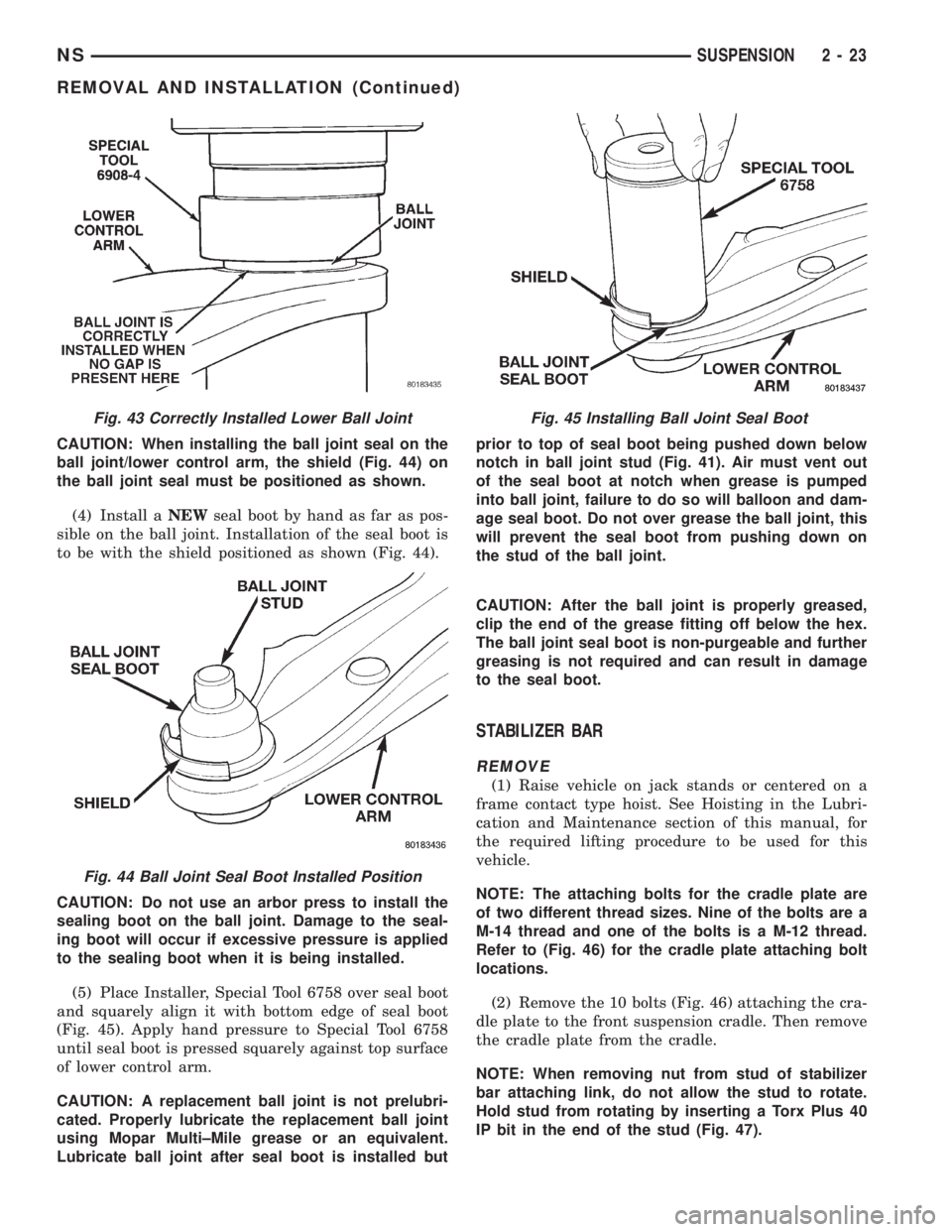
CAUTION: When installing the ball joint seal on the
ball joint/lower control arm, the shield (Fig. 44) on
the ball joint seal must be positioned as shown.
(4) Install aNEWseal boot by hand as far as pos-
sible on the ball joint. Installation of the seal boot is
to be with the shield positioned as shown (Fig. 44).
CAUTION: Do not use an arbor press to install the
sealing boot on the ball joint. Damage to the seal-
ing boot will occur if excessive pressure is applied
to the sealing boot when it is being installed.
(5) Place Installer, Special Tool 6758 over seal boot
and squarely align it with bottom edge of seal boot
(Fig. 45). Apply hand pressure to Special Tool 6758
until seal boot is pressed squarely against top surface
of lower control arm.
CAUTION: A replacement ball joint is not prelubri-
cated. Properly lubricate the replacement ball joint
using Mopar Multi±Mile grease or an equivalent.
Lubricate ball joint after seal boot is installed butprior to top of seal boot being pushed down below
notch in ball joint stud (Fig. 41). Air must vent out
of the seal boot at notch when grease is pumped
into ball joint, failure to do so will balloon and dam-
age seal boot. Do not over grease the ball joint, this
will prevent the seal boot from pushing down on
the stud of the ball joint.
CAUTION: After the ball joint is properly greased,
clip the end of the grease fitting off below the hex.
The ball joint seal boot is non-purgeable and further
greasing is not required and can result in damage
to the seal boot.
STABILIZER BAR
REMOVE
(1) Raise vehicle on jack stands or centered on a
frame contact type hoist. See Hoisting in the Lubri-
cation and Maintenance section of this manual, for
the required lifting procedure to be used for this
vehicle.
NOTE: The attaching bolts for the cradle plate are
of two different thread sizes. Nine of the bolts are a
M-14 thread and one of the bolts is a M-12 thread.
Refer to (Fig. 46) for the cradle plate attaching bolt
locations.
(2) Remove the 10 bolts (Fig. 46) attaching the cra-
dle plate to the front suspension cradle. Then remove
the cradle plate from the cradle.
NOTE: When removing nut from stud of stabilizer
bar attaching link, do not allow the stud to rotate.
Hold stud from rotating by inserting a Torx Plus 40
IP bit in the end of the stud (Fig. 47).
Fig. 43 Correctly Installed Lower Ball Joint
Fig. 44 Ball Joint Seal Boot Installed Position
Fig. 45 Installing Ball Joint Seal Boot
NSSUSPENSION 2 - 23
REMOVAL AND INSTALLATION (Continued)
Page 58 of 1938
CAUTION: Wheel bearing damage will result if
after loosening hub nut, vehicle is rolled on the
ground or the weight of the vehicle is allowed to be
supported by the tires.
(3) With the aid of a helper applying the brakes to
keep the front hub from turning,loosen but do not
removethe hub nut.The hub and driveshaft are
splined together through the knuckle (bearing)
and retained by the hub nut.
(4) Raise vehicle on jack stands or centered on a
frame contact type hoist. See Hoisting in the Lubri-
cation and Maintenance section of this manual, for
the required lifting procedure to be used for this
vehicle.
(5) Remove wheel lug nuts, and front tire and
wheel assembly.
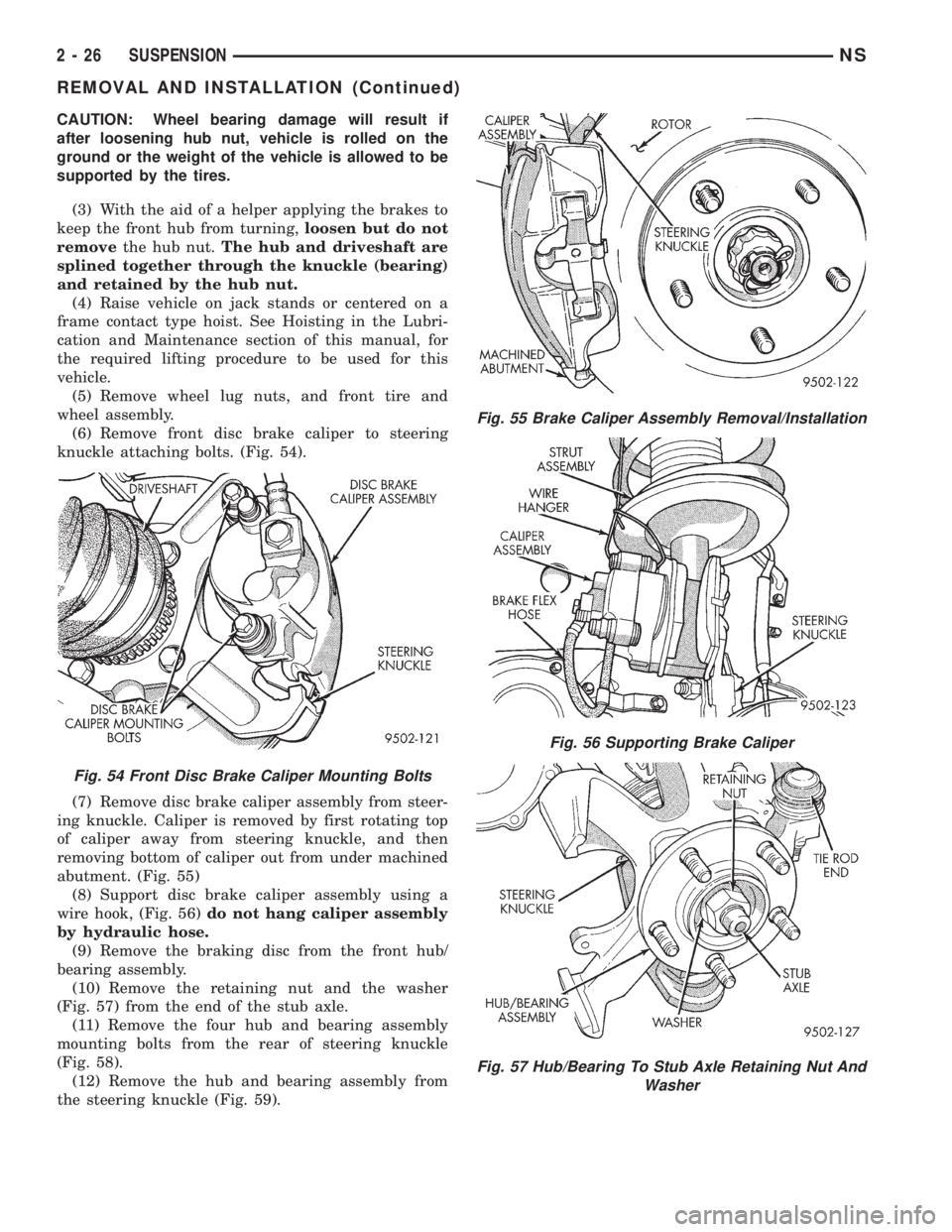
(6) Remove front disc brake caliper to steering
knuckle attaching bolts. (Fig. 54).
(7) Remove disc brake caliper assembly from steer-
ing knuckle. Caliper is removed by first rotating top
of caliper away from steering knuckle, and then
removing bottom of caliper out from under machined
abutment. (Fig. 55)
(8) Support disc brake caliper assembly using a
wire hook, (Fig. 56)do not hang caliper assembly
by hydraulic hose.
(9) Remove the braking disc from the front hub/
bearing assembly.
(10) Remove the retaining nut and the washer
(Fig. 57) from the end of the stub axle.
(11) Remove the four hub and bearing assembly
mounting bolts from the rear of steering knuckle
(Fig. 58).
(12) Remove the hub and bearing assembly from
the steering knuckle (Fig. 59).
Fig. 54 Front Disc Brake Caliper Mounting Bolts
Fig. 55 Brake Caliper Assembly Removal/Installation
Fig. 56 Supporting Brake Caliper
Fig. 57 Hub/Bearing To Stub Axle Retaining Nut And
Washer
2 - 26 SUSPENSIONNS
REMOVAL AND INSTALLATION (Continued)
Page 60 of 1938
sequence until all nuts are torqued to half specifica-
tion. Then repeat the tightening sequence to the full
specified torque of 129 N´m (95 ft. lbs.).
(7) Lower vehicle to the ground.
CAUTION: When tightening hub/bearing assembly
to stub shaft retaining nut, do not exceed the max-
imum torque of 244 N´m (180 ft. lbs.).
(8) With vehicle brakes applied to keep vehicle
from moving, torque stub shaft to hub/bearing assem-
bly retaining nut to 244 N´m (180 ft. lbs.).
(9) Check the Toe setting on the vehicle and reset
if not within specifications.
FRONT WHEEL MOUNTING STUDS
REMOVE
CAUTION: If a wheel attaching stud needs to be
replaced in the hub and bearing assembly the studs
CAN NOT be hammered out of the hub flange. If a
stud is removed by hammering it out of the bearing
flange, damage to the hub and bearing assembly
will occur leading to premature bearing failure.
The following procedure and special tools shown
MUST BEused when replacing wheel attaching
studs.
The hub and bearing assembly does not require
removal from the steering knuckle to replace wheel
attaching studs in the hub and bearing assembly.
(1) Raise vehicle on jackstands or centered on a
frame contact type hoist. See Hoisting in the Lubri-
cation and Maintenance section of this manual for
the required lifting procedure to be used for this
vehicle.
(2) Remove the front wheel and tire assembly from
the vehicle.
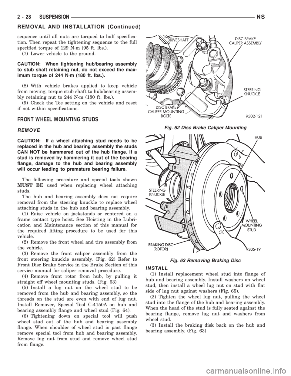
(3) Remove the front caliper assembly from the
front steering knuckle assembly. (Fig. 62) Refer to
Front Disc Brake Service in the Brake Section of this
service manual for caliper removal procedure.
(4) Remove front rotor from hub, by pulling it
straight off wheel mounting studs. (Fig. 63)
(5) Install a lug nut on the wheel stud to be
removed from the hub and bearing assembly, so the
threads on the stud are even with end of lug nut.
Install Remover, Special Tool C-4150A on hub and
bearing assembly flange and wheel stud (Fig. 64).
(6) Tightening down on special tool will push
wheel stud out of the hub and bearing assembly
flange. When shoulder of wheel stud is past flange
remove special tool from hub and bearing assembly.
Remove lug nut from stud and remove wheel stud
from flange.
INSTALL
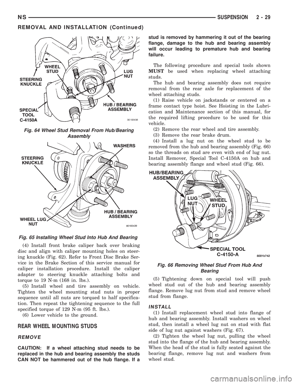
(1) Install replacement wheel stud into flange of
hub and bearing assembly. Install washers on wheel
stud, then install a wheel lug nut on stud with flat
side of lug nut against washers (Fig. 65).
(2) Tighten the wheel lug nut, pulling the wheel
stud into the flange of the hub and bearing assembly.
When the head of the stud is fully seated against the
bearing flange, remove lug nut and washers from
wheel stud.
(3) Install the braking disk back on the hub and
bearing assembly. (Fig. 63)
Fig. 62 Disc Brake Caliper Mounting
Fig. 63 Removing Braking Disc
2 - 28 SUSPENSIONNS
REMOVAL AND INSTALLATION (Continued)
Page 61 of 1938
(4) Install front brake caliper back over braking
disc and align with caliper mounting holes on steer-
ing knuckle (Fig. 62). Refer to Front Disc Brake Ser-
vice in the Brake Section of this service manual for
caliper installation procedure. Install the caliper
adapter to steering knuckle attaching bolts and
torque to 19 N´m (168 in. lbs.).
(5) Install wheel and tire assembly on vehicle.
Tighten the wheel mounting stud nuts in proper
sequence until all nuts are torqued to half specifica-
tion. Then repeat the tightening sequence to the full
specified torque of 129 N´m (95 ft. lbs.).
(6) Lower vehicle to the ground.
REAR WHEEL MOUNTING STUDS
REMOVE
CAUTION: If a wheel attaching stud needs to be
replaced in the hub and bearing assembly the studs
CAN NOT be hammered out of the hub flange. If astud is removed by hammering it out of the bearing
flange, damage to the hub and bearing assembly
will occur leading to premature hub and bearing
failure.
The following procedure and special tools shown
MUSTbe used when replacing wheel attaching
studs.
The hub and bearing assembly does not require
removal from the rear axle for replacement of the
wheel attaching studs.
(1) Raise vehicle on jackstands or centered on a
frame contact type hoist. See Hoisting in the Lubri-
cation and Maintenance section of this manual, for
the required lifting procedure to be used for this
vehicle.
(2) Remove the rear wheel and tire assembly.
(3) Remove the rear brake drum.
(4) Install a lug nut on the wheel stud to be
removed from the hub and bearing assembly (Fig. 66)
so the threads on stud are even with end of lug nut.
Install Remover, Special Tool C-4150A on hub and
bearing assembly flange and wheel stud (Fig. 66).
(5) Tightening down on special tool will push
wheel stud out of the hub and bearing assembly
flange. Remove lug nut from stud and remove wheel
stud from flange.
INSTALL
(1) Install replacement wheel stud into flange of
hub and bearing assembly. Install washers on wheel
stud, then install a wheel lug nut on stud with flat
side of lug nut against washers (Fig. 67).
(2) Tighten the wheel lug nut, pulling the wheel
stud into the flange of the hub and bearing assembly.
When the head of the stud is fully seated against the
bearing flange, remove lug nut and washers from
wheel stud.
Fig. 64 Wheel Stud Removal From Hub/Bearing
Assembly
Fig. 65 Installing Wheel Stud Into Hub And Bearing
Fig. 66 Removing Wheel Stud From Hub And
Bearing
NSSUSPENSION 2 - 29
REMOVAL AND INSTALLATION (Continued)
Page 71 of 1938
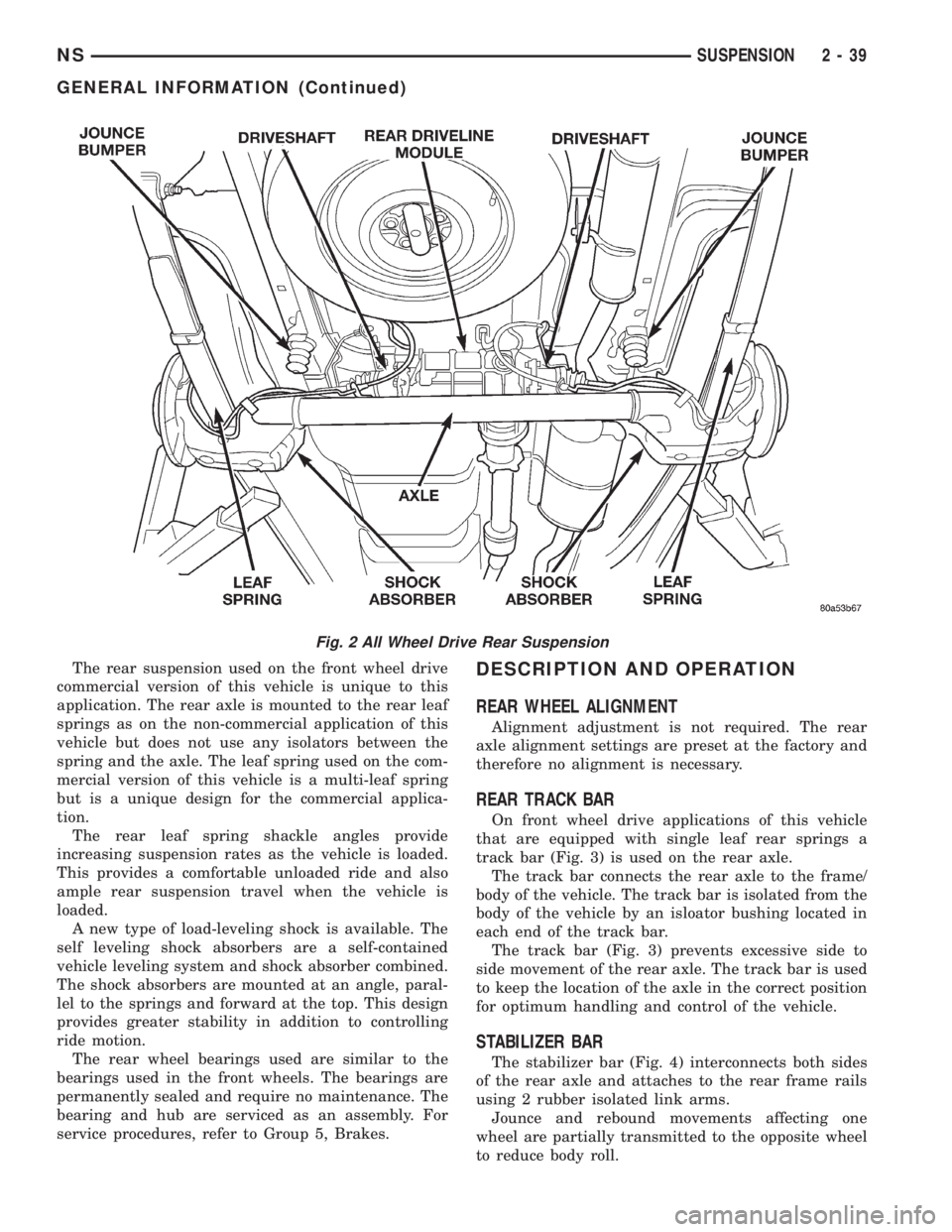
The rear suspension used on the front wheel drive
commercial version of this vehicle is unique to this
application. The rear axle is mounted to the rear leaf
springs as on the non-commercial application of this
vehicle but does not use any isolators between the
spring and the axle. The leaf spring used on the com-
mercial version of this vehicle is a multi-leaf spring
but is a unique design for the commercial applica-
tion.
The rear leaf spring shackle angles provide
increasing suspension rates as the vehicle is loaded.
This provides a comfortable unloaded ride and also
ample rear suspension travel when the vehicle is
loaded.
A new type of load-leveling shock is available. The
self leveling shock absorbers are a self-contained
vehicle leveling system and shock absorber combined.
The shock absorbers are mounted at an angle, paral-
lel to the springs and forward at the top. This design
provides greater stability in addition to controlling
ride motion.
The rear wheel bearings used are similar to the
bearings used in the front wheels. The bearings are
permanently sealed and require no maintenance. The
bearing and hub are serviced as an assembly. For
service procedures, refer to Group 5, Brakes.DESCRIPTION AND OPERATION
REAR WHEEL ALIGNMENT
Alignment adjustment is not required. The rear
axle alignment settings are preset at the factory and
therefore no alignment is necessary.
REAR TRACK BAR
On front wheel drive applications of this vehicle
that are equipped with single leaf rear springs a
track bar (Fig. 3) is used on the rear axle.
The track bar connects the rear axle to the frame/
body of the vehicle. The track bar is isolated from the
body of the vehicle by an isloator bushing located in
each end of the track bar.
The track bar (Fig. 3) prevents excessive side to
side movement of the rear axle. The track bar is used
to keep the location of the axle in the correct position
for optimum handling and control of the vehicle.
STABILIZER BAR
The stabilizer bar (Fig. 4) interconnects both sides
of the rear axle and attaches to the rear frame rails
using 2 rubber isolated link arms.
Jounce and rebound movements affecting one
wheel are partially transmitted to the opposite wheel
to reduce body roll.
Fig. 2 All Wheel Drive Rear Suspension
NSSUSPENSION 2 - 39
GENERAL INFORMATION (Continued)
Page 119 of 1938
CAUTION: When installing the tension clip on the
automatic adjuster, it must be located on only the
threaded area of the adjuster assembly (Fig. 66). If
it is located on a non-threaded area of the adjuster,
the function of the automatic adjuster will be
affected.
(7) Install the tension clip (Fig. 66) attaching the
upper return spring to the automatic adjuster assem-
bly.
(8) Install the brake shoe to brake shoe lower
return springs on the brake shoes (Fig. 64) and (Fig.
65).
(9) Install automatic adjustment lever on the lead-
ing brake shoe of the rear brake assembly (Fig. 63).
(10) Install the actuating spring on the automatic
adjustment lever and leading brake shoe assembly
(Fig. 62).
(11) Verify that the automatic adjuster lever has
positive contact with the star wheel on the automatic
adjuster assembly.
(12) When all components of both rear brake
assemblies are correctly and fully installed, remove
the locking pliers from the front park brake cable.
(13) Adjust brake shoes assemblies so as not to
interfere with brake drum installation.
(14) Install the rear brake drums on the hubs.
(15) Adjust rear brake shoes per Adjusting Rear
Brakes procedure in the service adjustments section
of the service manual.
(16) Install the wheel and tire assembly.
(17) Push the park brake pedal to the floor once
and release pedal. This will automatically remove the
slack from and correctly adjust the park brake
cables.
(18) Tighten the wheel mounting stud nuts in
proper sequence until all nuts are torqued to half
specification. Then repeat the tightening sequence to
the full specified torque of 130 N´m (95 ft. lbs.).
(19) Road test vehicle. The automatic adjuster will
continue the brake adjustment during the road test
of the vehicle.
BRAKE SUPPORT PLATE (REAR DRUM BRAKES)
REMOVE
(1) Raise vehicle on jackstands or centered on a
frame contact type hoist. See Hoisting in the Lubri-
cation and Maintenance section of this service man-
ual for required lifting procedure.
(2) Remove wheel and tire.
(3) Remove brake drum from hub/bearing.
(4) Remove brake shoes from brake support plate.
Refer to Rear Brake Shoe Removal in the removal
and installation section in this group of the service
manual for the required procedure.(5) Disconnect the park brake cable from the park
brake actuation lever.
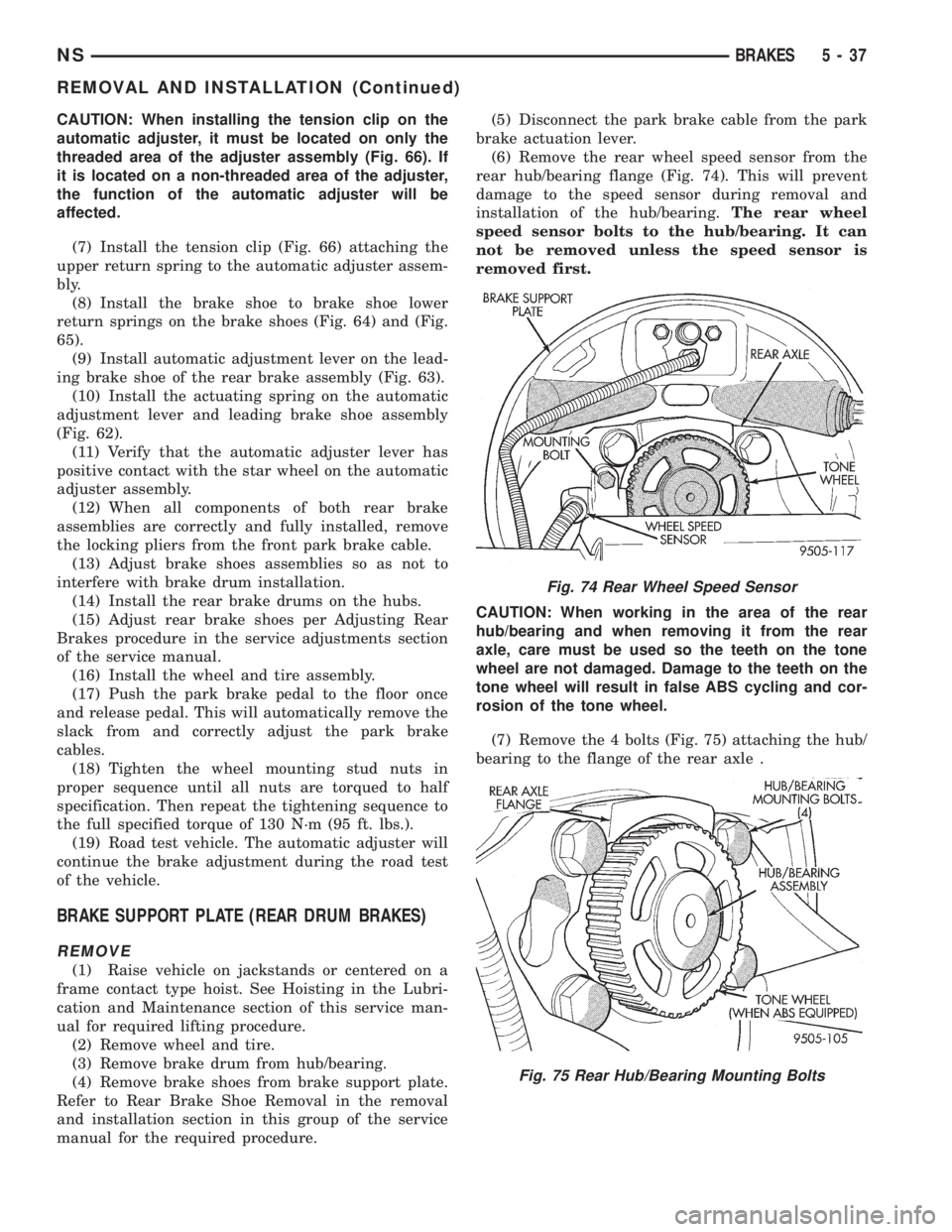
(6) Remove the rear wheel speed sensor from the
rear hub/bearing flange (Fig. 74). This will prevent
damage to the speed sensor during removal and
installation of the hub/bearing.The rear wheel
speed sensor bolts to the hub/bearing. It can
not be removed unless the speed sensor is
removed first.
CAUTION: When working in the area of the rear
hub/bearing and when removing it from the rear
axle, care must be used so the teeth on the tone
wheel are not damaged. Damage to the teeth on the
tone wheel will result in false ABS cycling and cor-
rosion of the tone wheel.
(7) Remove the 4 bolts (Fig. 75) attaching the hub/
bearing to the flange of the rear axle .
Fig. 74 Rear Wheel Speed Sensor
Fig. 75 Rear Hub/Bearing Mounting Bolts
NSBRAKES 5 - 37
REMOVAL AND INSTALLATION (Continued)
Page 122 of 1938

(3) Remove the rear wheel cylinder attaching bolts
(Fig. 81). Then pull wheel cylinder assembly off the
brake support plate.
INSTALL
(1) Apply MopartGasket In-A-Tube or equivalent
sealant around wheel cylinder mounting surface in
brake support plate.
(2) Install wheel cylinder onto brake support, and
tighten the wheel cylinder to brake support plate
attaching bolts (Fig. 81) to 8 N´m (75 in. lbs.).
(3) Attach hydraulic brake tube to wheel cylinder,
(Fig. 81) and tighten tube to wheel cylinder fitting to
16 N´m (142 in. lbs.).
(4) Install brake shoes on support plate.
(5) Install rear brake drum onto rear hub. Install
rear wheel and tire assembly, tighten wheel stud
nuts to 129 N´m (95 ft. lbs.).
(6) Adjust the rear brakes, (See Adjusting Service
Brakes) in Service Adjustments section in this group
of the service manual.
(7) Bleed the entire brake system. See (Bleeding
Brake System) in Service Adjustments section in this
group of the service manual.
HUB/BEARING
FRONT WHEEL DRIVE
REMOVE
(1) Raise vehicle on jackstands or centered on a
frame contact type hoist. See Hoisting in the Lubri-
cation and Maintenance section of this service man-
ual for required lifting procedure.
(2) Remove wheel and tire.
(3) Remove brake drum from hub/bearing.
(4) Remove rear wheel speed sensor from rear hub/
bearing (Fig. 82). This will prevent damage to the
speed sensor during removal and installation of the
hub/bearing.The rear wheel speed sensor bolts
to the hub/bearing. It can not be removed
unless the speed sensor is removed first.
CAUTION: When working in the area of the rear
hub/bearing and when removing it from the rear
axle, care must be used so the teeth on the tone
wheel are not damaged. Damage to the teeth on the
tone wheel will result in false ABS cycling and cor-
rosion of the tone wheel.
(5) Remove the 4 bolts (Fig. 83) attaching the hub/
bearing to the rear axle.
CAUTION: Corrosion may occur between the hub/
bearing and the axle. If this occurs the hub/bearing
will be difficult to remove from the axle. If the hub/
bearing will not come out of the axle by pulling onit by hand, do not pound on the hub/bearing to
remove it from the axle. Pounding on the hub/bear-
ing to remove it from the axle will damage the hub/
bearing. This damage will result in noise or failure
of the bearing.
(6) If hub/bearing cannot be removed from the axle
by hand, use Remover Special Tool 8214 (Fig. 84) and
following procedure to press the hub/bearing out of
the axle.
(a) Place Special Tool 8214-1 over tone wheel
and against cast flange of hub/bearing (Fig. 84)
(b) Put a dab of grease in the bolt pilot hole on
the back of Special Tool 8214-1.
(c) Insert Special Tool 8214-2 into the hole in the
bottom of the end casting on the axle (Fig. 84).
Special Tool 8214-2 should be against and sup-
ported by the axle plate (Fig. 84) when pressing
the wheel bearing out of the axle.If Special Tool
8214-2 will not fit into the hole in the end
casting, file or grind the flashing from the
hole until tool fits properly.
Fig. 82 Rear Wheel Speed Sensor
Fig. 83 Rear Hub/Bearing Mounting Bolts
5 - 40 BRAKESNS
REMOVAL AND INSTALLATION (Continued)
Page 161 of 1938
REAR DRUM BRAKE SHOE ADJUSTMENT
NOTE: Normally, self adjusting drum brakes will
not require manual brake shoe adjustment.
Although in the event of a brake reline it is advis-
able to make the initial adjustment manually to
speed up the adjusting time.
(1) Raise the vehicle so that the rear wheels are
free to turn. See Hoisting Recommendations in the
Lubrication And Maintenance Section, at the front of
this service manual.
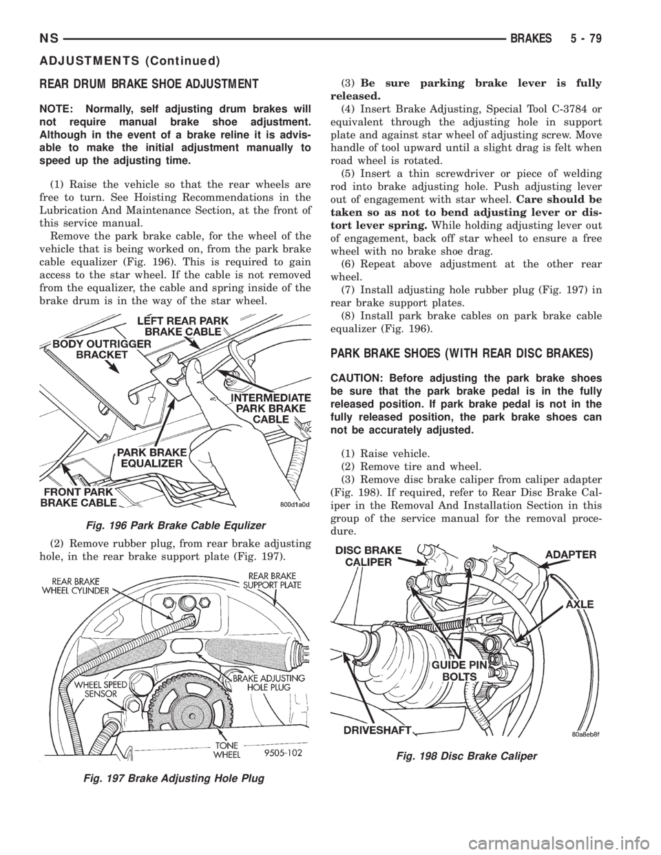
Remove the park brake cable, for the wheel of the
vehicle that is being worked on, from the park brake
cable equalizer (Fig. 196). This is required to gain
access to the star wheel. If the cable is not removed
from the equalizer, the cable and spring inside of the
brake drum is in the way of the star wheel.
(2) Remove rubber plug, from rear brake adjusting
hole, in the rear brake support plate (Fig. 197).(3)Be sure parking brake lever is fully
released.
(4) Insert Brake Adjusting, Special Tool C-3784 or
equivalent through the adjusting hole in support
plate and against star wheel of adjusting screw. Move
handle of tool upward until a slight drag is felt when
road wheel is rotated.
(5) Insert a thin screwdriver or piece of welding
rod into brake adjusting hole. Push adjusting lever
out of engagement with star wheel.Care should be
taken so as not to bend adjusting lever or dis-
tort lever spring.While holding adjusting lever out
of engagement, back off star wheel to ensure a free
wheel with no brake shoe drag.
(6) Repeat above adjustment at the other rear
wheel.
(7) Install adjusting hole rubber plug (Fig. 197) in
rear brake support plates.
(8) Install park brake cables on park brake cable
equalizer (Fig. 196).
PARK BRAKE SHOES (WITH REAR DISC BRAKES)
CAUTION: Before adjusting the park brake shoes
be sure that the park brake pedal is in the fully
released position. If park brake pedal is not in the
fully released position, the park brake shoes can
not be accurately adjusted.
(1) Raise vehicle.
(2) Remove tire and wheel.
(3) Remove disc brake caliper from caliper adapter
(Fig. 198). If required, refer to Rear Disc Brake Cal-
iper in the Removal And Installation Section in this
group of the service manual for the removal proce-
dure.
Fig. 196 Park Brake Cable Equlizer
Fig. 197 Brake Adjusting Hole Plug
Fig. 198 Disc Brake Caliper
NSBRAKES 5 - 79
ADJUSTMENTS (Continued)
Page 187 of 1938

CAUTION: Because of the flexible section in the
primary and secondary brake tubes, and the brake
tubes between the HCU and the proportioning
valve, the brake tubes must be held in proper ori-
entation when tightened and torqued. These tubes
must not contact each other or other vehicle com-
ponents when installed.
CAUTION: When installing the chassis brake tubes
on the HCU valve block, they must be located cor-
rectly in the valve block to ensure proper ABS oper-
ation. Refer to (Fig. 27) for the correct chassis
brake tube locations.
NOTE: The chassis brake tube attachment loca-
tions to the HCU, are marked on the bottom of the
HCU mounting bracket.
(6) Install the 6 chassis brake tubes into their cor-
rect port locations on the HCU valve block as shown
in (Fig. 27). Tighten the tube nuts to a torque of 17
N´m (145 in. lbs.).
NOTE: Before installing the 25 way connector in
the CAB be sure the seal is properly installed in the
connector.
(7) Install the 25 way connector on the CAB using
the following procedure. Position the 25 way connec-
tor in the socket of the CAB and carefully push it
down as far as possible. When connector is fully
seated by hand into the CAB socket, push in the con-
nector lock (Fig. 26). This will pull the connector into
the socket of the CAB and lock it in the installed
position.
(8) Install the routing clips (Fig. 33) on the brake
tubes.(9) Lower vehicle.
(10) Connect negative cable back on negative post
of the battery.
(11) Bleed the base brakes and the ABS brakes
hydraulic system. Refer to the Bleeding ABS System
in this section of the manual for the proper bleeding
procedure.
(12) Road test vehicle to ensure proper operation
of the base and ABS brake systems.
WHEEL SPEED SENSOR (FRONT)
REMOVE
(1) Raise vehicle on jack stands or centered on a
frame contact type hoist. See Hoisting in the Lubri-
cation and Maintenance section of this service man-
ual, for the required lifting procedure to be used for
this vehicle.
(2) Remove the tire and wheel assembly from the
vehicle.
(3) Remove the 2 screws (Fig. 34) attaching front
channel bracket and grommet retainer to the outer
frame rail.
CAUTION: When disconnecting the wheel speed
sensor from vehicle wiring harness, be careful not
to damage pins on connector
(4) Pull speed sensor cable grommet and connector
through the hole in the strut tower (Fig. 35). Discon-
nect speed sensor cable from vehicle wiring harness
(Fig. 35).
(5) Remove the wheel speed sensor head to steer-
ing knuckle attaching bolt (Fig. 36).
(6) Remove sensor head from steering knuckle. If
the sensor has seized, due to corrosion,DO NOT
USE PLIERS ON SENSOR HEAD.Use a hammer
and a punch and tap edge of sensor ear, rocking the
sensor side to side until free.
Fig. 33 Brake Tube Routing Clips
Fig. 34 Front Speed Sensor Cable Channel Bracket
NSBRAKES 5 - 105
REMOVAL AND INSTALLATION (Continued)
Page 188 of 1938

(7) Remove the wheel speed sensor cable grommets
from the retaining bracket (Fig. 37).(8) Remove front wheel speed sensor assembly
from the vehicle.
INSTALL
CAUTION: Proper installation of wheel speed sen-
sor cables is critical to continued system operation.
Be sure that cables are installed in retainers. Fail-
ure to install cables in retainers as shown in this
section may result in contact with moving parts
and/or over extension of cables, resulting in an
open circuit.
(1) Connect the front wheel speed sensor cable to
the vehicle wiring harness connector (Fig. 35). Be
sure speed sensor cable connector is fully seated and
locked into vehicle wiring harness connector, then
insert cable and grommet into hole in strut tower
(Fig. 35).
CAUTION: When installing channel bracket, do not
pinch the speed sensor cable under the channel
bracket.
(2) Install the channel bracket and grommet
retainer on the frame rail (Fig. 34).
(3) Install the 2 bolts (Fig. 34) attaching the chan-
nel bracket to frame. Tighten the 2 attaching bolts to
a torque of 11 N´m (95 in. lbs.).
(4) Insert speed sensor cable grommets into inter-
mediate bracket on strut (Fig. 37). Route cable from
strut to steering knuckle on the rearward side of the
stabilizer bar link.
(5) Install the wheel speed sensor to steering
knuckle attaching bolt (Fig. 36). Tighten the speed
sensor attaching bolt to a torque of 12 N´m (105 in.
lbs.)
(6) Check the air gap between the face of the
wheel speed sensor and the top surface of the tone-
wheel. Air gap must be less then the maximum
allowable tolerance of 1.2 mm (.047 in.).
(7) Install the wheel and tire assembly on vehicle.
(8) Road test vehicle to ensure proper operation of
the base and ABS brake systems.
WHEEL SPEED SENSOR (REAR FWD)
REMOVE
(1) Raise vehicle on jack stands or centered on a
frame contact type hoist. See Hoisting in the Lubri-
cation and Maintenance section of this manual, for
the required lifting procedure to be used for this
vehicle.
(2) Remove the tire and wheel assembly from the
vehicle.
Fig. 35 Speed Sensor Cable To Vehicle Wiring
Harness
Fig. 36 Front Wheel Speed Sensor Attaching Bolt
Fig. 37 Front Wheel Speed Sensor Cable Routing
5 - 106 BRAKESNS
REMOVAL AND INSTALLATION (Continued)