spark plugs CHRYSLER VOYAGER 1996 Owner's Manual
[x] Cancel search | Manufacturer: CHRYSLER, Model Year: 1996, Model line: VOYAGER, Model: CHRYSLER VOYAGER 1996Pages: 1938, PDF Size: 55.84 MB
Page 1060 of 1938
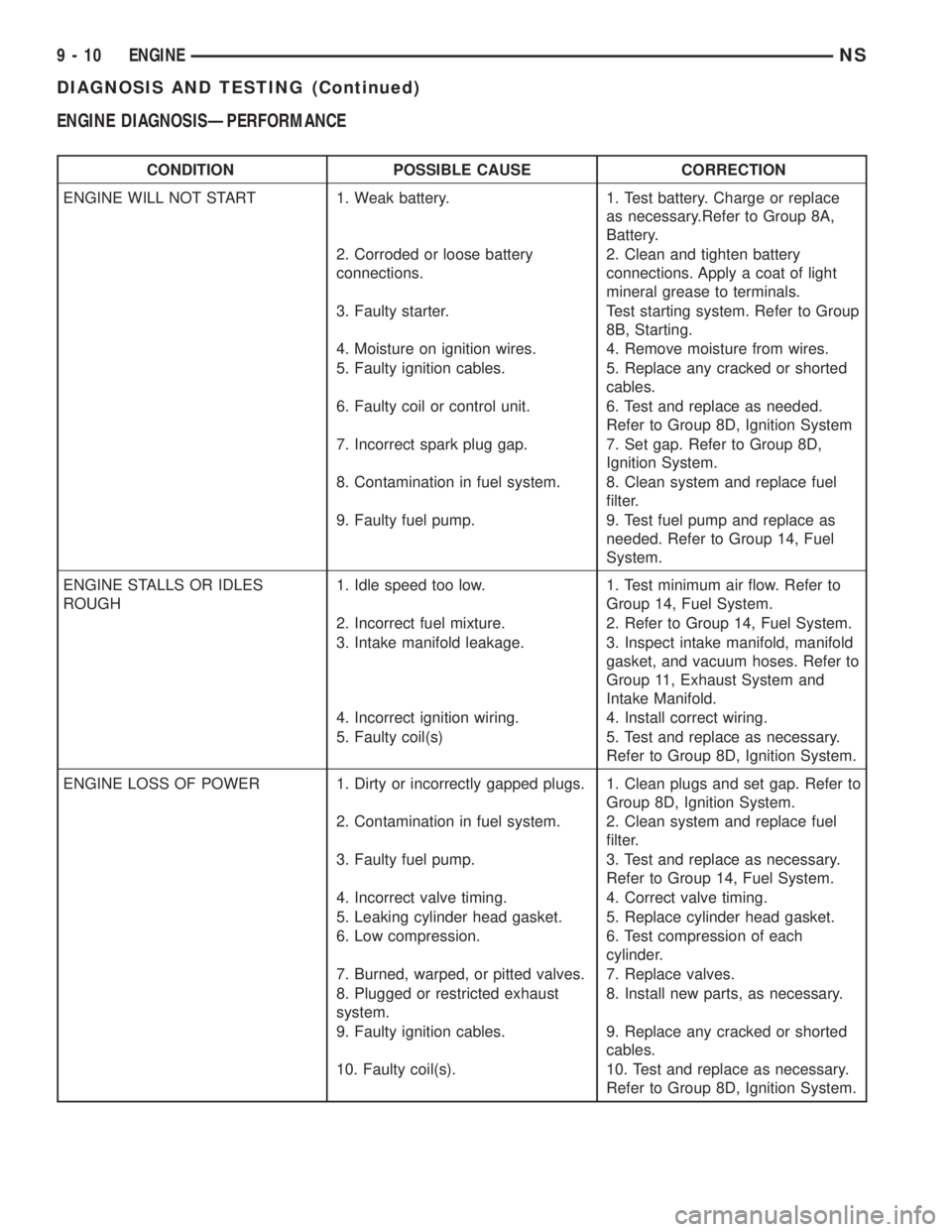
ENGINE DIAGNOSISÐPERFORMANCE
CONDITION POSSIBLE CAUSE CORRECTION
ENGINE WILL NOT START 1. Weak battery. 1. Test battery. Charge or replace
as necessary.Refer to Group 8A,
Battery.
2. Corroded or loose battery
connections.2. Clean and tighten battery
connections. Apply a coat of light
mineral grease to terminals.
3. Faulty starter. Test starting system. Refer to Group
8B, Starting.
4. Moisture on ignition wires. 4. Remove moisture from wires.
5. Faulty ignition cables. 5. Replace any cracked or shorted
cables.
6. Faulty coil or control unit. 6. Test and replace as needed.
Refer to Group 8D, Ignition System
7. Incorrect spark plug gap. 7. Set gap. Refer to Group 8D,
Ignition System.
8. Contamination in fuel system. 8. Clean system and replace fuel
filter.
9. Faulty fuel pump. 9. Test fuel pump and replace as
needed. Refer to Group 14, Fuel
System.
ENGINE STALLS OR IDLES
ROUGH1. Idle speed too low. 1. Test minimum air flow. Refer to
Group 14, Fuel System.
2. Incorrect fuel mixture. 2. Refer to Group 14, Fuel System.
3. Intake manifold leakage. 3. Inspect intake manifold, manifold
gasket, and vacuum hoses. Refer to
Group 11, Exhaust System and
Intake Manifold.
4. Incorrect ignition wiring. 4. Install correct wiring.
5. Faulty coil(s) 5. Test and replace as necessary.
Refer to Group 8D, Ignition System.
ENGINE LOSS OF POWER 1. Dirty or incorrectly gapped plugs. 1. Clean plugs and set gap. Refer to
Group 8D, Ignition System.
2. Contamination in fuel system. 2. Clean system and replace fuel
filter.
3. Faulty fuel pump. 3. Test and replace as necessary.
Refer to Group 14, Fuel System.
4. Incorrect valve timing. 4. Correct valve timing.
5. Leaking cylinder head gasket. 5. Replace cylinder head gasket.
6. Low compression. 6. Test compression of each
cylinder.
7. Burned, warped, or pitted valves. 7. Replace valves.
8. Plugged or restricted exhaust
system.8. Install new parts, as necessary.
9. Faulty ignition cables. 9. Replace any cracked or shorted
cables.
10. Faulty coil(s). 10. Test and replace as necessary.
Refer to Group 8D, Ignition System.
9 - 10 ENGINENS
DIAGNOSIS AND TESTING (Continued)
Page 1061 of 1938
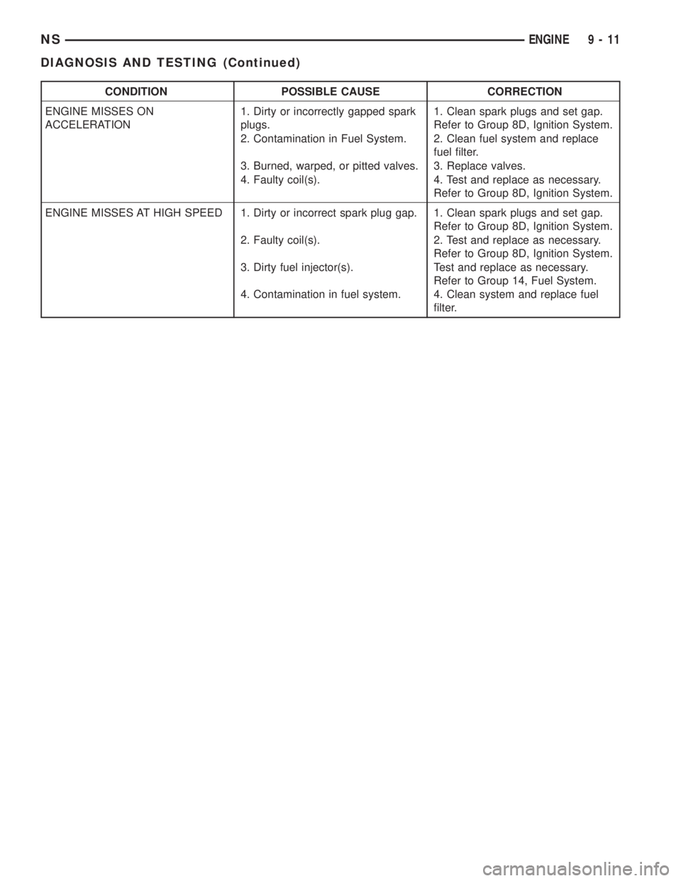
CONDITION POSSIBLE CAUSE CORRECTION
ENGINE MISSES ON
ACCELERATION1. Dirty or incorrectly gapped spark
plugs.1. Clean spark plugs and set gap.
Refer to Group 8D, Ignition System.
2. Contamination in Fuel System. 2. Clean fuel system and replace
fuel filter.
3. Burned, warped, or pitted valves. 3. Replace valves.
4. Faulty coil(s). 4. Test and replace as necessary.
Refer to Group 8D, Ignition System.
ENGINE MISSES AT HIGH SPEED 1. Dirty or incorrect spark plug gap. 1. Clean spark plugs and set gap.
Refer to Group 8D, Ignition System.
2. Faulty coil(s). 2. Test and replace as necessary.
Refer to Group 8D, Ignition System.
3. Dirty fuel injector(s). Test and replace as necessary.
Refer to Group 14, Fuel System.
4. Contamination in fuel system. 4. Clean system and replace fuel
filter.
NSENGINE 9 - 11
DIAGNOSIS AND TESTING (Continued)
Page 1063 of 1938
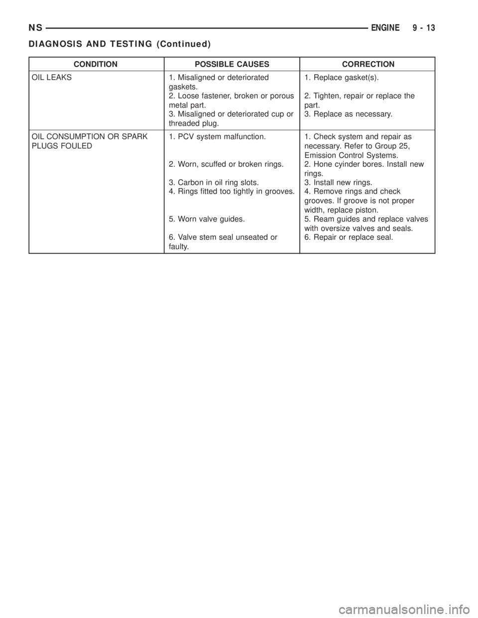
CONDITION POSSIBLE CAUSES CORRECTION
OIL LEAKS 1. Misaligned or deteriorated
gaskets.1. Replace gasket(s).
2. Loose fastener, broken or porous
metal part.2. Tighten, repair or replace the
part.
3. Misaligned or deteriorated cup or
threaded plug.3. Replace as necessary.
OIL CONSUMPTION OR SPARK
PLUGS FOULED1. PCV system malfunction. 1. Check system and repair as
necessary. Refer to Group 25,
Emission Control Systems.
2. Worn, scuffed or broken rings. 2. Hone cyinder bores. Install new
rings.
3. Carbon in oil ring slots. 3. Install new rings.
4. Rings fitted too tightly in grooves. 4. Remove rings and check
grooves. If groove is not proper
width, replace piston.
5. Worn valve guides. 5. Ream guides and replace valves
with oversize valves and seals.
6. Valve stem seal unseated or
faulty.6. Repair or replace seal.
NSENGINE 9 - 13
DIAGNOSIS AND TESTING (Continued)
Page 1083 of 1938
NOTE: THE TIMING MARK ON THE SPROCKET,
THE (LOWER) NICKEL PLATED LINK, AND THE
ARROW ON THE SIDE OF THE GEAR COVER
SHOULD LINE UP WHEN THE BALANCE SHAFTS
ARE TIMED CORRECTLY.
(9) If the sprockets are timed correctly install the
balance shaft bolts and tighten to 28 N´m (250 in.
lbs.). A wood block placed between crankcase and
crankshaft counterbalance will prevent crankshaft
and gear rotation.
CHAIN TENSIONING
(1) Install chain tensioner loosely assembled.
(2) Position guide on double ended stud making
sure tab on the guide fits into slot on the gear cover.
Install and tighten nut/washer assembly to 12 N´m
(105 in. lbs.).
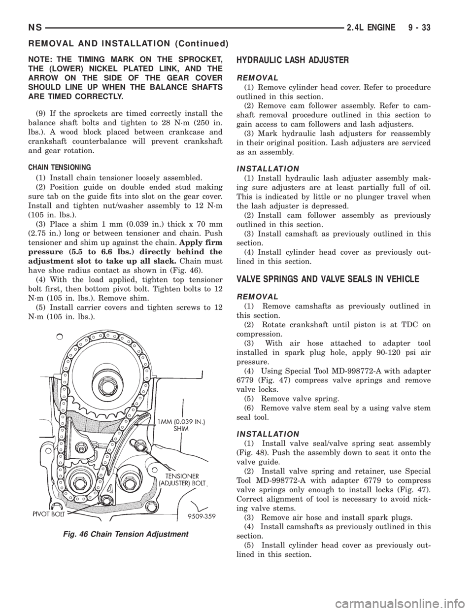
(3) Place a shim 1 mm (0.039 in.) thick x 70 mm
(2.75 in.) long or between tensioner and chain. Push
tensioner and shim up against the chain.Apply firm
pressure (5.5 to 6.6 lbs.) directly behind the
adjustment slot to take up all slack.Chain must
have shoe radius contact as shown in (Fig. 46).
(4) With the load applied, tighten top tensioner
bolt first, then bottom pivot bolt. Tighten bolts to 12
N´m (105 in. lbs.). Remove shim.
(5) Install carrier covers and tighten screws to 12
N´m (105 in. lbs.).HYDRAULIC LASH ADJUSTER
REMOVAL
(1) Remove cylinder head cover. Refer to procedure
outlined in this section.
(2) Remove cam follower assembly. Refer to cam-
shaft removal procedure outlined in this section to
gain access to cam followers and lash adjusters.
(3) Mark hydraulic lash adjusters for reassembly
in their original position. Lash adjusters are serviced
as an assembly.
INSTALLATION
(1) Install hydraulic lash adjuster assembly mak-
ing sure adjusters are at least partially full of oil.
This is indicated by little or no plunger travel when
the lash adjuster is depressed.
(2) Install cam follower assembly as previously
outlined in this section.
(3) Install camshaft as previously outlined in this
section.
(4) Install cylinder head cover as previously out-
lined in this section.
VALVE SPRINGS AND VALVE SEALS IN VEHICLE
REMOVAL
(1) Remove camshafts as previously outlined in
this section.
(2) Rotate crankshaft until piston is at TDC on
compression.
(3) With air hose attached to adapter tool
installed in spark plug hole, apply 90-120 psi air
pressure.
(4) Using Special Tool MD-998772-A with adapter
6779 (Fig. 47) compress valve springs and remove
valve locks.
(5) Remove valve spring.
(6) Remove valve stem seal by a using valve stem
seal tool.
INSTALLATION
(1) Install valve seal/valve spring seat assembly
(Fig. 48). Push the assembly down to seat it onto the
valve guide.
(2) Install valve spring and retainer, use Special
Tool MD-998772-A with adapter 6779 to compress
valve springs only enough to install locks (Fig. 47).
Correct alignment of tool is necessary to avoid nick-
ing valve stems.
(3) Remove air hose and install spark plugs.
(4) Install camshafts as previously outlined in this
section.
(5) Install cylinder head cover as previously out-
lined in this section.
Fig. 46 Chain Tension Adjustment
NS2.4L ENGINE 9 - 33
REMOVAL AND INSTALLATION (Continued)
Page 1107 of 1938

TORQUE CHART 2.4L
DESCRIPTION TORQUE
Balance Shaft Carrier to Block
Bolts.....................54N´m(40ft.lbs.)
Balance Shaft Gear Cover
Double Ended Fastener......12N´m(105 in. lbs.)
Balance Shaft Sprockets
Bolts....................28N´m(250 in. lbs.)
Balance Shaft Chain Tensioner
Bolts....................12N´m(105 in. lbs.)
Balance Shaft Carrier Cover
Fasteners................12N´m(105 in. lbs.)
Camshaft Sensor Pick Up
Bolts.....................27N´m(20ft.lbs.)
Timing Belt Cover
Outer to Inner Attaching Bolts M6.......4.5 N´m
(40 in. lbs.)
Inner Cover to Head/Oil Pump Bolts M6 . . .12 N´m
(105 in. lbs.)
Camshaft Sprocket
Bolt.....................101 N´m (75 ft. lbs.)
Connecting Rod Cap
Bolts..............................27N´m
(20 ft. lbs.) Plus 1/4 Turn
Crankshaft Main Bearing Cap/Bedplate
M8 Bedplate Bolts.........34N´m(250 in. lbs.)
Main Cap Bolts M11..................41N´m
(30 ft. lbs.) Plus 1/4 Turn
Crankshaft Damper
Bolt....................135 N´m (100 ft. lbs.)
Cylinder Head
Bolts........Refer To Cylinder Head Installation
Cylinder Head Cover
Bolts....................12N´m(105 in. lbs.)DESCRIPTION TORQUE
Engine Mount Bracket
Bolts.....................61N´m(45ft.lbs.)
Engine MountÐFront and Rear
Through Bolt...............61N´m(45ft.lbs.)
Exhaust Manifold to Cylinder Head
Bolts....................23N´m(200 in. lbs.)
Exhaust Manifold Heat Shield
Bolts....................12N´m(105 in. lbs.)
Front Torque BracketÐ2.0/2.4L Engine
Bolts.....................33N´m(24ft.lbs.)
Front Torque Bracket StrutÐ2.0/2.4L Engine
Long Bolts................110N´m(80ft.lbs.)
Short Bolt.................61N´m(45ft.lbs.)
Intake Manifold
Bolts.....................27N´m(20ft.lbs.)
Oil Filter
Filter.....................20N´m(15ft.lbs.)
Oil Pan
Oil Pan Bolts.............12N´m(105 in. lbs.)
Drain Plug.................27N´m(20ft.lbs.)
Oil Pump Attaching
Bolts....................28N´m(250 in. lbs.)
Oil Pump Cover Fastener. . . .12 N´m (105 in. lbs.)
Oil Pump Pick-up Tube Bolt . .28 N´m (250 in. lbs.)
Oil Pump Relief Valve Cap. . . .41 N´m (30 ft. lbs.)
Rear Torque Bracket
Bolts....................110N´m(80ft.lbs.)
Spark Plugs
Plugs.....................28N´m(20ft.lbs.)
Thermostat Housing
Bolts....................23N´m(200 in lbs.)
Timing Belt Tensioner Assembly
Bolts.....................61N´m(45ft.lbs.)
Water Pump Mounting
Bolts....................12N´m(105 in. lbs.)
NS2.4L ENGINE 9 - 57
SPECIFICATIONS (Continued)
Page 1140 of 1938
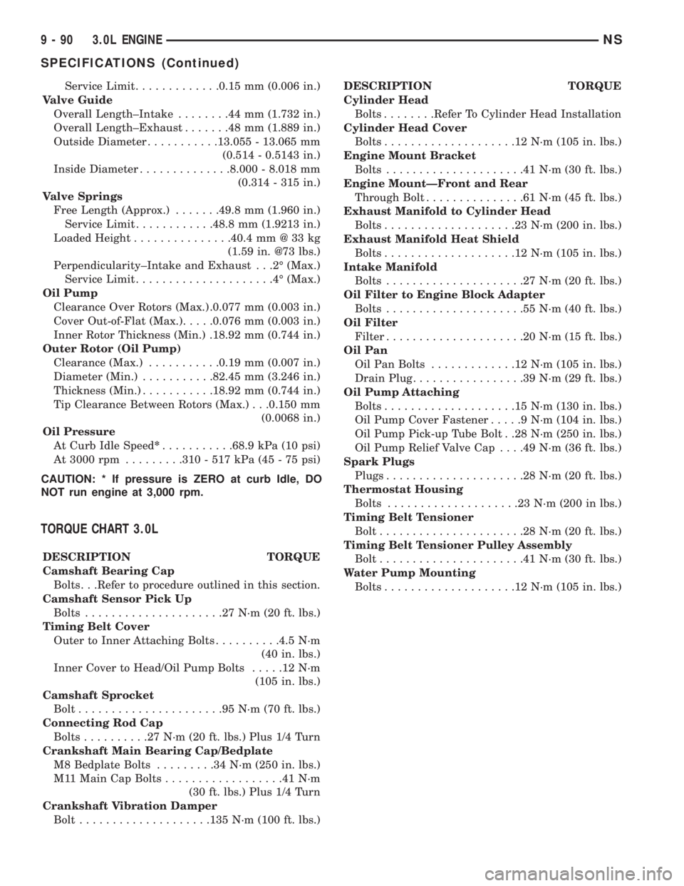
Service Limit.............0.15 mm (0.006 in.)
Valve Guide
Overall Length±Intake........44mm(1.732 in.)
Overall Length±Exhaust.......48mm(1.889 in.)
Outside Diameter...........13.055 - 13.065 mm
(0.514 - 0.5143 in.)
Inside Diameter..............8.000 - 8.018 mm
(0.314 - 315 in.)
Valve Springs
Free Length (Approx.).......49.8 mm (1.960 in.)
Service Limit............48.8 mm (1.9213 in.)
Loaded Height...............40.4 mm @ 33 kg
(1.59 in. @73 lbs.)
Perpendicularity±Intake and Exhaust . . .2É (Max.)
Service Limit.....................4É(Max.)
Oil Pump
Clearance Over Rotors (Max.) .0.077 mm (0.003 in.)
Cover Out-of-Flat (Max.).....0.076 mm (0.003 in.)
Inner Rotor Thickness (Min.) .18.92 mm (0.744 in.)
Outer Rotor (Oil Pump)
Clearance (Max.)...........0.19 mm (0.007 in.)
Diameter (Min.)...........82.45 mm (3.246 in.)
Thickness (Min.)...........18.92 mm (0.744 in.)
Tip Clearance Between Rotors (Max.) . . .0.150 mm
(0.0068 in.)
Oil Pressure
At Curb Idle Speed*...........68.9 kPa (10 psi)
At 3000 rpm.........310 - 517 kPa (45 - 75 psi)
CAUTION: * If pressure is ZERO at curb Idle, DO
NOT run engine at 3,000 rpm.
TORQUE CHART 3.0L
DESCRIPTION TORQUE
Camshaft Bearing Cap
Bolts. . .Refer to procedure outlined in this section.
Camshaft Sensor Pick Up
Bolts.....................27N´m(20ft.lbs.)
Timing Belt Cover
Outer to Inner Attaching Bolts..........4.5 N´m
(40 in. lbs.)
Inner Cover to Head/Oil Pump Bolts.....12N´m
(105 in. lbs.)
Camshaft Sprocket
Bolt......................95N´m(70ft.lbs.)
Connecting Rod Cap
Bolts..........27N´m(20ft.lbs.) Plus 1/4 Turn
Crankshaft Main Bearing Cap/Bedplate
M8 Bedplate Bolts.........34N´m(250 in. lbs.)
M11 Main Cap Bolts..................41N´m
(30 ft. lbs.) Plus 1/4 Turn
Crankshaft Vibration Damper
Bolt....................135 N´m (100 ft. lbs.)DESCRIPTION TORQUE
Cylinder Head
Bolts........Refer To Cylinder Head Installation
Cylinder Head Cover
Bolts....................12N´m(105 in. lbs.)
Engine Mount Bracket
Bolts.....................41N´m(30ft.lbs.)
Engine MountÐFront and Rear
Through Bolt...............61N´m(45ft.lbs.)
Exhaust Manifold to Cylinder Head
Bolts....................23N´m(200 in. lbs.)
Exhaust Manifold Heat Shield
Bolts....................12N´m(105 in. lbs.)
Intake Manifold
Bolts.....................27N´m(20ft.lbs.)
Oil Filter to Engine Block Adapter
Bolts.....................55N´m(40ft.lbs.)
Oil Filter
Filter.....................20N´m(15ft.lbs.)
Oil Pan
Oil Pan Bolts.............12N´m(105 in. lbs.)
Drain Plug.................39N´m(29ft.lbs.)
Oil Pump Attaching
Bolts....................15N´m(130 in. lbs.)
Oil Pump Cover Fastener.....9N´m(104 in. lbs.)
Oil Pump Pick-up Tube Bolt . .28 N´m (250 in. lbs.)
Oil Pump Relief Valve Cap. . . .49 N´m (36 ft. lbs.)
Spark Plugs
Plugs.....................28N´m(20ft.lbs.)
Thermostat Housing
Bolts....................23N´m(200 in lbs.)
Timing Belt Tensioner
Bolt......................28N´m(20ft.lbs.)
Timing Belt Tensioner Pulley Assembly
Bolt......................41N´m(30ft.lbs.)
Water Pump Mounting
Bolts....................12N´m(105 in. lbs.)
9 - 90 3.0L ENGINENS
SPECIFICATIONS (Continued)
Page 1146 of 1938
NOTE: Worn valve guides or cocked springs are
sometimes mistaken for noisy tappets. If such is
the case, noise may be dampened by applying side
thrust on the valve spring. If noise is not apprecia-
bly reduced, it can be assumed the noise is in the
tappet. Inspect the rocker arm push rod sockets
and push rod ends for wear.
Valve tappet noise ranges from light noise to a
heavy click. A light noise is usually caused by exces-
sive leak-down around the unit plunger which will
necessitate replacing the tappet, or by the plunger
partially sticking in the tappet body cylinder. A heavy
click is caused either by a tappet check valve not
seating, or by foreign particles becoming wedged
between the plunger and the tappet body causing the
plunger to stick in the down position. This heavy
click will be accompanied by excessive clearance
between the valve stem and rocker arm as valve
closes. In either case, tappet assembly should be
removed for inspection and cleaning.
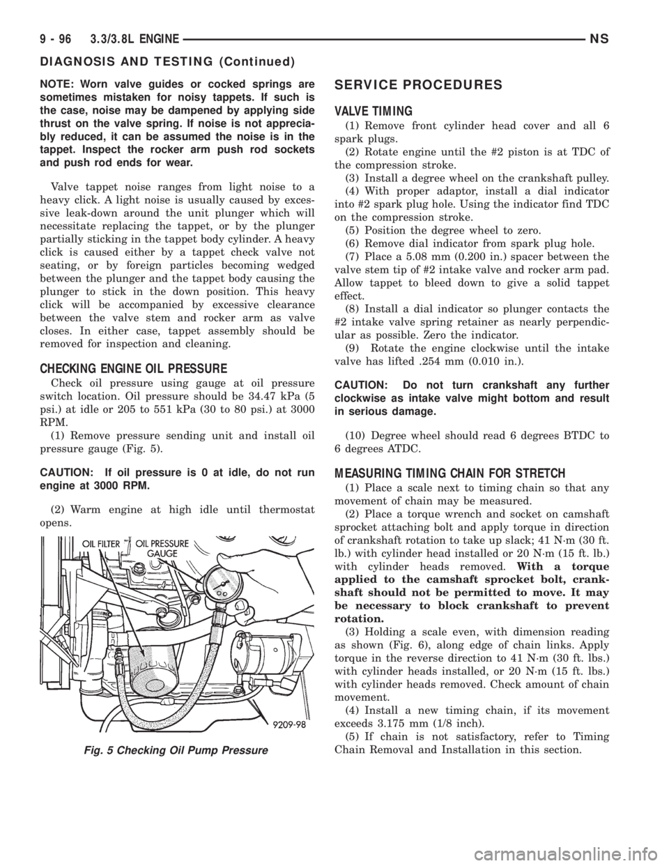
CHECKING ENGINE OIL PRESSURE
Check oil pressure using gauge at oil pressure
switch location. Oil pressure should be 34.47 kPa (5
psi.) at idle or 205 to 551 kPa (30 to 80 psi.) at 3000
RPM.
(1) Remove pressure sending unit and install oil
pressure gauge (Fig. 5).
CAUTION: If oil pressure is 0 at idle, do not run
engine at 3000 RPM.
(2) Warm engine at high idle until thermostat
opens.
SERVICE PROCEDURES
VALVE TIMING
(1) Remove front cylinder head cover and all 6
spark plugs.
(2) Rotate engine until the #2 piston is at TDC of
the compression stroke.
(3) Install a degree wheel on the crankshaft pulley.
(4) With proper adaptor, install a dial indicator
into #2 spark plug hole. Using the indicator find TDC
on the compression stroke.
(5) Position the degree wheel to zero.
(6) Remove dial indicator from spark plug hole.
(7) Place a 5.08 mm (0.200 in.) spacer between the
valve stem tip of #2 intake valve and rocker arm pad.
Allow tappet to bleed down to give a solid tappet
effect.
(8) Install a dial indicator so plunger contacts the
#2 intake valve spring retainer as nearly perpendic-
ular as possible. Zero the indicator.
(9) Rotate the engine clockwise until the intake
valve has lifted .254 mm (0.010 in.).
CAUTION: Do not turn crankshaft any further
clockwise as intake valve might bottom and result
in serious damage.
(10) Degree wheel should read 6 degrees BTDC to
6 degrees ATDC.
MEASURING TIMING CHAIN FOR STRETCH
(1) Place a scale next to timing chain so that any
movement of chain may be measured.
(2) Place a torque wrench and socket on camshaft
sprocket attaching bolt and apply torque in direction
of crankshaft rotation to take up slack; 41 N´m (30 ft.
lb.) with cylinder head installed or 20 N´m (15 ft. lb.)
with cylinder heads removed.With a torque
applied to the camshaft sprocket bolt, crank-
shaft should not be permitted to move. It may
be necessary to block crankshaft to prevent
rotation.
(3) Holding a scale even, with dimension reading
as shown (Fig. 6), along edge of chain links. Apply
torque in the reverse direction to 41 N´m (30 ft. lbs.)
with cylinder heads installed, or 20 N´m (15 ft. lbs.)
with cylinder heads removed. Check amount of chain
movement.
(4) Install a new timing chain, if its movement
exceeds 3.175 mm (1/8 inch).
(5) If chain is not satisfactory, refer to Timing
Chain Removal and Installation in this section.
Fig. 5 Checking Oil Pump Pressure
9 - 96 3.3/3.8L ENGINENS
DIAGNOSIS AND TESTING (Continued)
Page 1157 of 1938
(4) Remove upper intake manifold. Refer to Group
11, Exhaust System and Intake Manifolds for proce-
dure.
(5) Remove cylinder head covers and spark plugs.
(6) Remove electrical connector from ignition coils.
(7) Using suitable socket and flex handle at crank-
shaft pulley retaining screw, turn engine so the num-
ber 1 piston is at Top Dead Center on the
compression stroke.
(8) Remove rocker arms with rocker shaft and
install a dummy shaft. The rocker arms should not
be disturbed and left on shaft.
(9) With air hose attached to spark plug adapter
installed in number 1 spark plug hole, apply 90 to
100 psi air pressure (620.5 to 689 kPa). This is to
hold valves in place while servicing components.
(10) Using Tool C-4682 or equivalent, compress
valve spring and remove retainer valve locks and
valve spring.
(11) The intake valve stem seals should be pushed
firmly and squarely over the valve guide using the
valve stem as guide.Do Not Forceseal against top
of guide. When installing the valve retainer locks,
compress the springonly enoughto install the
locks.
CAUTION: Do not pinch seal between retainer and
top of valve guide.
(12) Follow the same procedure on the remaining 5
cylinders using the firing sequence 1-2-3-4-5-6.Make
sure piston in cylinder is at TDC on the valve
spring that is being covered.
(13) Remove spark plug adapter tool.
(14) Remove dummy shaft and install rocker shaft
assembly and tighten screws to 28 N´m (250 in. lbs.).
(15) Install cylinder head covers tighten screws to
14 N´m (120 in. lbs.) and electrical connector to igni-
tion coils.
(16) Install Intake Manifold. Refer to Group 11,
Exhaust System and Intake Manifold for procedure.
(17) Connect negative cable to battery.
CYLINDER HEAD COVER
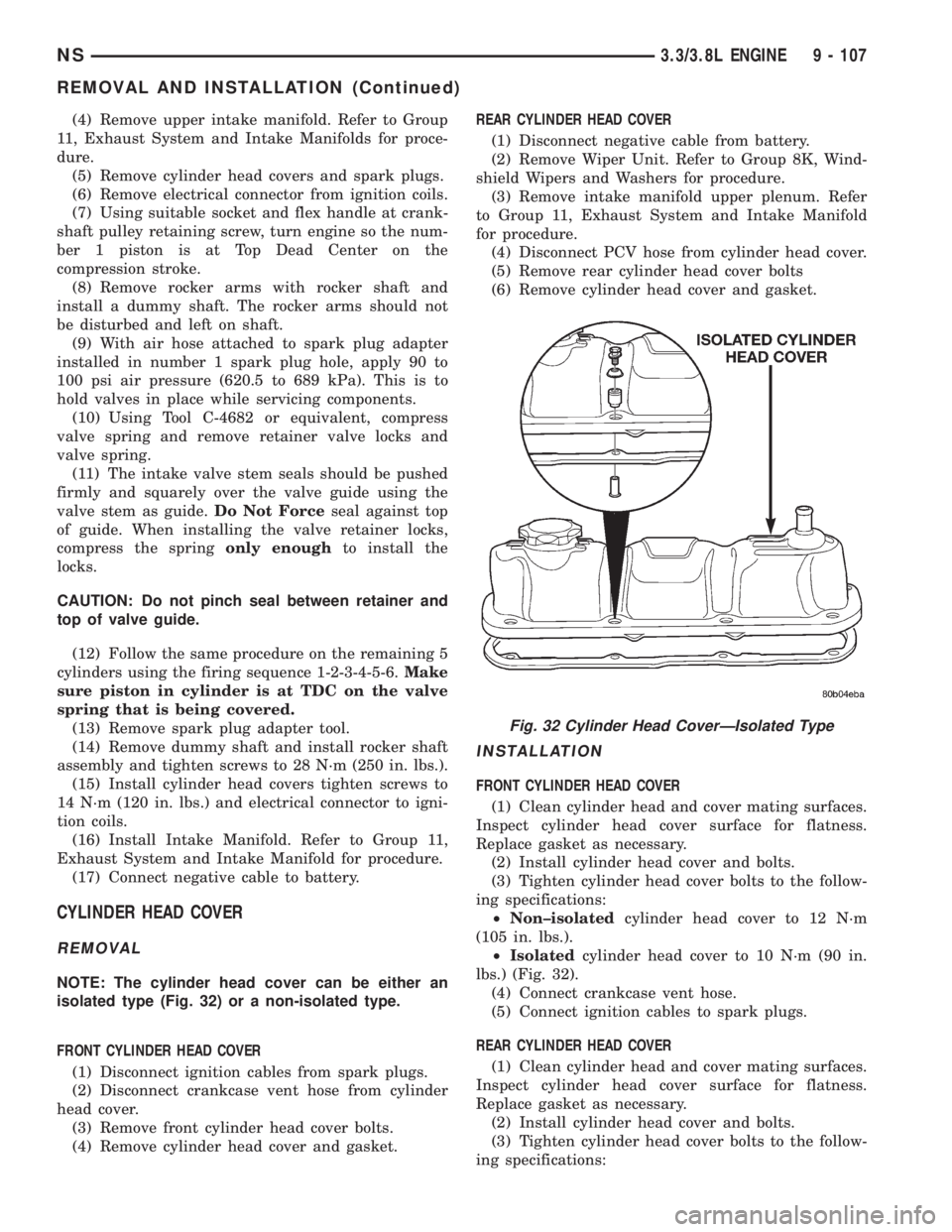
REMOVAL
NOTE: The cylinder head cover can be either an
isolated type (Fig. 32) or a non-isolated type.
FRONT CYLINDER HEAD COVER
(1) Disconnect ignition cables from spark plugs.
(2) Disconnect crankcase vent hose from cylinder
head cover.
(3) Remove front cylinder head cover bolts.
(4) Remove cylinder head cover and gasket.REAR CYLINDER HEAD COVER
(1) Disconnect negative cable from battery.
(2) Remove Wiper Unit. Refer to Group 8K, Wind-
shield Wipers and Washers for procedure.
(3) Remove intake manifold upper plenum. Refer
to Group 11, Exhaust System and Intake Manifold
for procedure.
(4) Disconnect PCV hose from cylinder head cover.
(5) Remove rear cylinder head cover bolts
(6) Remove cylinder head cover and gasket.
INSTALLATION
FRONT CYLINDER HEAD COVER
(1) Clean cylinder head and cover mating surfaces.
Inspect cylinder head cover surface for flatness.
Replace gasket as necessary.
(2) Install cylinder head cover and bolts.
(3) Tighten cylinder head cover bolts to the follow-
ing specifications:
²Non±isolatedcylinder head cover to 12 N´m
(105 in. lbs.).
²Isolatedcylinder head cover to 10 N´m (90 in.
lbs.) (Fig. 32).
(4) Connect crankcase vent hose.
(5) Connect ignition cables to spark plugs.
REAR CYLINDER HEAD COVER
(1) Clean cylinder head and cover mating surfaces.
Inspect cylinder head cover surface for flatness.
Replace gasket as necessary.
(2) Install cylinder head cover and bolts.
(3) Tighten cylinder head cover bolts to the follow-
ing specifications:
Fig. 32 Cylinder Head CoverÐIsolated Type
NS3.3/3.8L ENGINE 9 - 107
REMOVAL AND INSTALLATION (Continued)
Page 1159 of 1938
(7) Inspect push rods and replace worn or bent
rods.
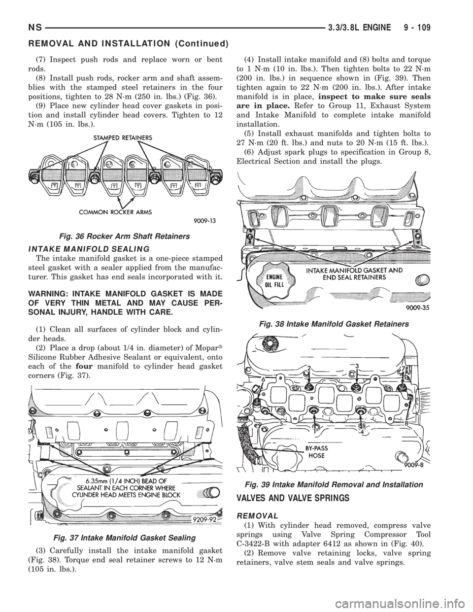
(8) Install push rods, rocker arm and shaft assem-
blies with the stamped steel retainers in the four
positions, tighten to 28 N´m (250 in. lbs.) (Fig. 36).
(9) Place new cylinder head cover gaskets in posi-
tion and install cylinder head covers. Tighten to 12
N´m (105 in. lbs.).
INTAKE MANIFOLD SEALING
The intake manifold gasket is a one-piece stamped
steel gasket with a sealer applied from the manufac-
turer. This gasket has end seals incorporated with it.
WARNING: INTAKE MANIFOLD GASKET IS MADE
OF VERY THIN METAL AND MAY CAUSE PER-
SONAL INJURY, HANDLE WITH CARE.
(1) Clean all surfaces of cylinder block and cylin-
der heads.
(2) Place a drop (about 1/4 in. diameter) of Mopart
Silicone Rubber Adhesive Sealant or equivalent, onto
each of thefourmanifold to cylinder head gasket
corners (Fig. 37).
(3) Carefully install the intake manifold gasket
(Fig. 38). Torque end seal retainer screws to 12 N´m
(105 in. lbs.).(4) Install intake manifold and (8) bolts and torque
to 1 N´m (10 in. lbs.). Then tighten bolts to 22 N´m
(200 in. lbs.) in sequence shown in (Fig. 39). Then
tighten again to 22 N´m (200 in. lbs.). After intake
manifold is in place,inspect to make sure seals
are in place.Refer to Group 11, Exhaust System
and Intake Manifold to complete intake manifold
installation.
(5) Install exhaust manifolds and tighten bolts to
27 N´m (20 ft. lbs.) and nuts to 20 N´m (15 ft. lbs.).
(6) Adjust spark plugs to specification in Group 8,
Electrical Section and install the plugs.
VALVES AND VALVE SPRINGS
REMOVAL
(1) With cylinder head removed, compress valve
springs using Valve Spring Compressor Tool
C-3422-B with adapter 6412 as shown in (Fig. 40).
(2) Remove valve retaining locks, valve spring
retainers, valve stem seals and valve springs.
Fig. 36 Rocker Arm Shaft Retainers
Fig. 37 Intake Manifold Gasket Sealing
Fig. 38 Intake Manifold Gasket Retainers
Fig. 39 Intake Manifold Removal and Installation
NS3.3/3.8L ENGINE 9 - 109
REMOVAL AND INSTALLATION (Continued)
Page 1214 of 1938
Valve Margin
Intake.....1.15 ± 1.48 mm (0.0452 ± 0.0582 in.)
Exhaust....1.475 ± 1.805 mm (0.058 ± 0.071 in.)
Valve Length (Overall)
Intake....114.69 ± 115.19 mm (4.515 ± 4.535 in.)
Exhaust . . 109.59 ± 110.09 mm (4.603 ± 4.623 in.)
Valve Stem Tip Height
Intake.......45.01 ± 46.07 mm (1.77 ± 1.81 in.)
Exhaust......43.51 ± 44.57 mm (1.71 ± 1.75 in.)
Stem Diameter
Intake.....5.934 ± 5.952 mm (0.234 ± 0.234 in.)
Exhaust....5.906 ± 5.924 mm (0.233 ± 0.233 in.)
Stem to Guide Clearance
Intake . . . 0.048 ± 0.066 mm (0.0018 ± 0.0025 in.)
Exhaust . 0.0736 ± 0.094 mm (0.0029 ± 0.0037 in.)
Max. Allowable Intake.....0.076 mm (0.003 in.)
Max. Allowable Exhaust....0.101 mm (0.004 in.)
Valve Springs
Free Length (Approx.)......44.4 mm (1.747 in.)
Nominal Force (Valve closed) . 91 N´m @ 39.8 mm
(67 ft. lbs. @ 1.57 in.)
Nominal Force (Valve open) . 239 N´m @ 32.6 mm
(176 lbs. @ 1.28 in.)
Installed Height..........40.18 mm (1.580 in.)
* SERVICE AS AN ASSEMBLY WITH ROCKER
ARM.
** ALL READINGS IN CRANKSHAFT DEGREES,
AT 0.5 mm (0.019 in.) OF VALVE LIFT.
TORQUE CHART 2.0L SOHC
DESCRIPTION...................TORQUE
Camshaft Sensor Pick Up
Bolts...................9.6N´m(85in.lbs.)
Camshaft Sprocket
Bolt....................115N´m(85ft.lbs.)
Connecting Rod Cap
Bolts.........27N´m(20ft.lbs.) Plus 1/4 Turn
CollarÐOil Pan to Transaxle
Step 1: Collar to Oil Pan Bolts . 3 N´m (30 in. lbs.)
Step 2: Collar to Transaxle
Bolts...................108N´m(80ft.lbs.)
Step 3: Collar to Oil Pan
Bolts....................54N´m(40ft.lbs.)
Crankshaft Main Bearing Cap/Bedplate
M8 Bedplate Bolts..........30N´m(22ft.lbs.)
M11 Main Cap Bolts........81N´m(60ft.lbs.)
Crankshaft Damper
Bolt...................142N´m(105 ft. lbs.)
Cylinder Head
Bolts.......Refer To Cylinder Head Installation
Cylinder Head Cover
Bolts...................12N´m(105 in. lbs.)
Engine Mount BracketÐRight
Bolts....................61N´m(45ft.lbs.)DESCRIPTION...................TORQUE
Engine Mounting
Bolts.......Refer to Engine Mount Installation
Exhaust Manifold to Cylinder Head
Bolts...................23N´m(200 in. lbs.)
Exhaust Manifold Heat Shield
Bolts...................12N´m(105 in. lbs.)
Intake Manifold
Bolts...................12N´m(105 in. lbs.)
Oil Filter Adapter
Fastener.................80N´m(60ft.lbs.)
Oil Filter.................20N´m(15ft.lbs.)
Oil Pan
Bolts...................12N´m(105 in. lbs.)
Drain Plug...............27N´m(20ft.lbs.)
Oil Pump Attaching
Bolts...................28N´m(250 in. lbs.)
Oil Pump Cover Fastener . . . 12 N´m (105 in. lbs.)
Oil Pump Pick-up Tube Bolt . 28 N´m (250 in. lbs.)
Oil Pump Relief Valve Cap . . . 41 N´m (30 ft. lbs.)
Rocker Arm Shaft
Bolts...................28N´m(250 in. lbs.)
Spark Plugs...............28N´m(20ft.lbs.)
Thermostat Housing
Bolts...................23N´m(200 in lbs.)
Timing Belt Cover
Bolts M6................12N´m(105 in. lbs.)
Timing Belt Mechanical Tensioner Assembly
Bolts...................28N´m(250 in. lbs.)
Timing Belt Hydraulic Tensioner
Pulley Bolt...............68N´m(50ft.lbs.)
Pivot Bracket Bolt..........31N´m(23ft.lbs.)
Tensioner Bolts............31N´m(23ft.lbs.)
Water Pump Mounting
Bolts...................12N´m(105 in. lbs.)
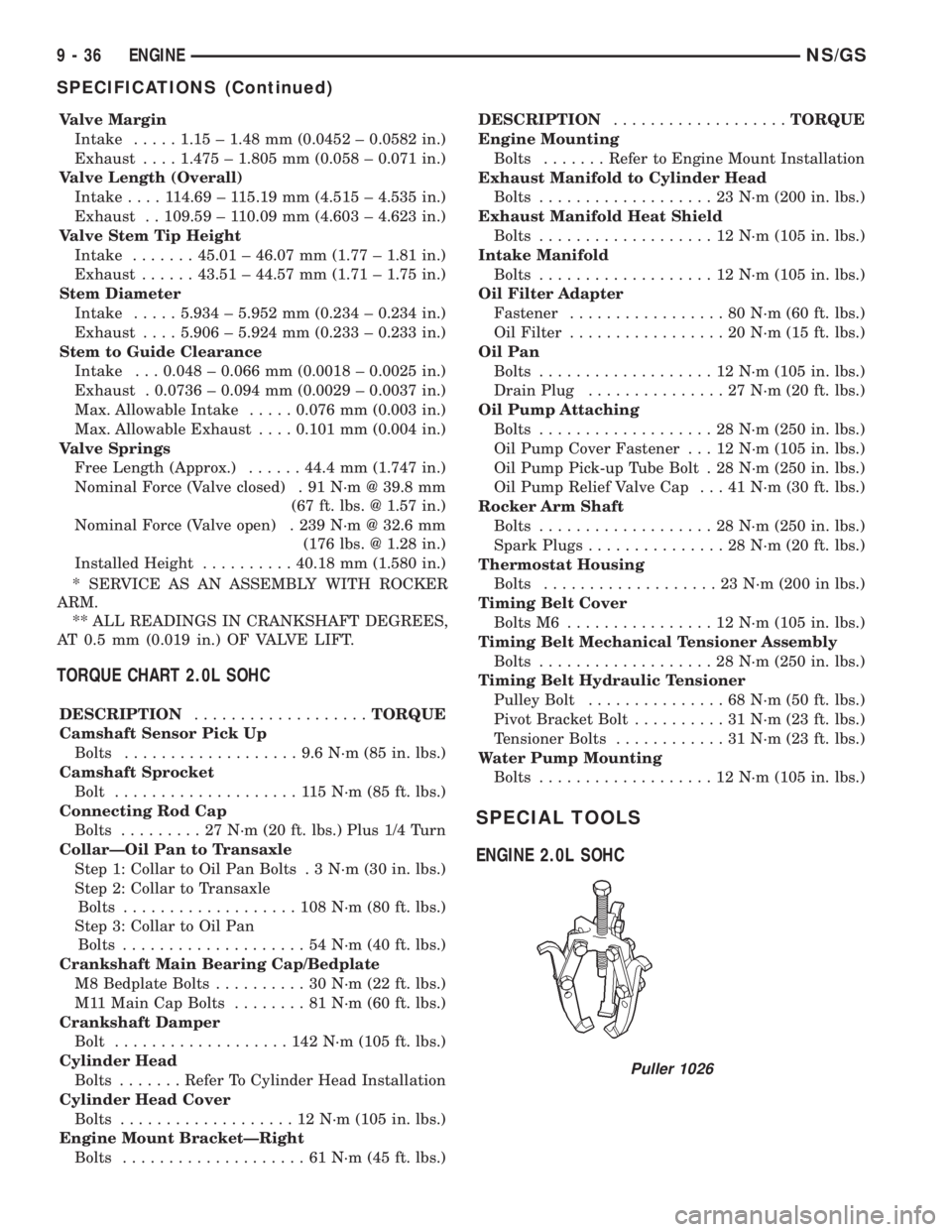
SPECIAL TOOLS
ENGINE 2.0L SOHC
Puller 1026
9 - 36 ENGINENS/GS
SPECIFICATIONS (Continued)