CHRYSLER VOYAGER 1996 Service Manual
Manufacturer: CHRYSLER, Model Year: 1996, Model line: VOYAGER, Model: CHRYSLER VOYAGER 1996Pages: 1938, PDF Size: 55.84 MB
Page 331 of 1938

REMOVAL
(1) Disconnect electrical connector from knock sen-
sor.
(2) Use a crow foot socket to remove the knock
sensor.
INSTALLATION
(1) Install knock sensor. Tighten knock sensor to
10 N´m (7 ft. lbs.) torque.Over or under tighten-
ing effects knock sensor performance, possibly
causing improper spark control.
(2) Attach electrical connector to knock sensor.
SPECIFICATIONS
IGNITION COILFig. 12 Knock Sensor
Coil ManufacturePrimary Resistance at 21ÉC-27ÉC
(70ÉF-80ÉF)Secondary Resistance at 21ÉC-
27ÉC (70ÉF-80ÉF)
Weastec (Aluminum Towers) 0.45 TO 0.65 Ohms 7,000 to 15,800 Ohms
Diamond Electric (Brass Towers) 0.45 TO 0.65 Ohms 7,000 to 15,800 Ohms
Coil PolarityCoil Polarity
NSIGNITION SYSTEM 8D - 33
REMOVAL AND INSTALLATION (Continued)
Page 332 of 1938

SPARK PLUG
* New Spark Plug Gap
TORQUE
DESCRIPTION......................TORQUE
3.3L Camshaft Position
Sensor Screw.............12N´m(105 in. lbs.)
3.3L Engine Coolant Sensor......7N´m(60in.lbs.)
3.3L Crankshaft Position
Sensor Screw.............12N´m(105 in. lbs.)
3.3/3.8L Ignition Coil.........12N´m(105 in. lbs.)
Ignition Switch...............2N´m(17in.lbs.)
Spark Plugs.................28N´m(20ft.lbs.)
SPARK PLUG CABLE RESISTANCEÐ3.3/3.8L
Engine Spark Plug Gap * Thread Size
3.3L RN14PMP5 0.048 TO 0.053 14mm (3/4 in.) reach
3.8L RN14PMP5 0.048 TO 0.053 14mm (3/4 in. ) reach
CABLE Maximum
Resistance
#1 18.5K ohms
#2 15.5K ohms
#3 20.4K ohms
#4 21.2K ohms
#5 27.7K ohms
#6 26.7K ohms
8D - 34 IGNITION SYSTEMNS
SPECIFICATIONS (Continued)
Page 333 of 1938
IGNITION SWITCH AND LOCK CYLINDER
INDEX
page page
DESCRIPTION AND OPERATION
IGNITION INTERLOCK.................... 35
LOCK KEY CYLINDER.................... 35
REMOVAL AND INSTALLATION
IGNITION INTERLOCK.................... 38IGNITION SWITCH....................... 35
LOCK CYLINDER HOUSING............... 38
LOCK KEY CYLINDER.................... 38
DESCRIPTION AND OPERATION
IGNITION INTERLOCK
All vehicles equipped with automatic transaxles
have an interlock system. The system prevents shift-
ing the vehicle out of Park unless the ignition lock
cylinder is in the Off, Run or Start position. In addi-
tion, the operator cannot rotate the key to the lock
position unless the shifter is in the park position. On
vehicles equipped with floor shift refer to Group 21 -
Transaxle for Automatic Transmission Shifter/Igni-
tion Interlock.
LOCK KEY CYLINDER
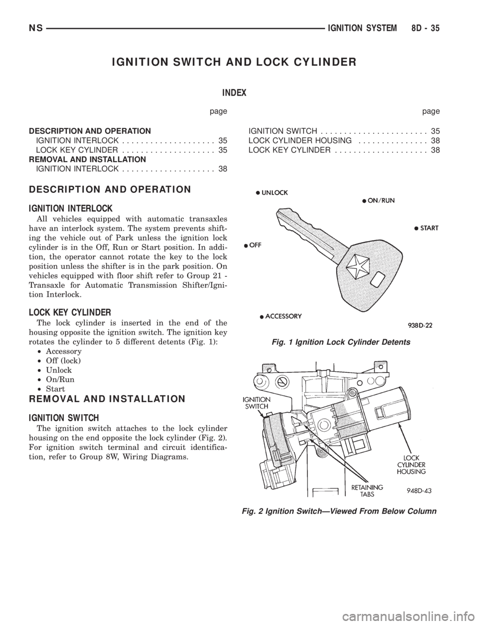
The lock cylinder is inserted in the end of the
housing opposite the ignition switch. The ignition key
rotates the cylinder to 5 different detents (Fig. 1):
²Accessory
²Off (lock)
²Unlock
²On/Run
²Start
REMOVAL AND INSTALLATION
IGNITION SWITCH
The ignition switch attaches to the lock cylinder
housing on the end opposite the lock cylinder (Fig. 2).
For ignition switch terminal and circuit identifica-
tion, refer to Group 8W, Wiring Diagrams.
Fig. 1 Ignition Lock Cylinder Detents
Fig. 2 Ignition SwitchÐViewed From Below Column
NSIGNITION SYSTEM 8D - 35
Page 334 of 1938
REMOVAL
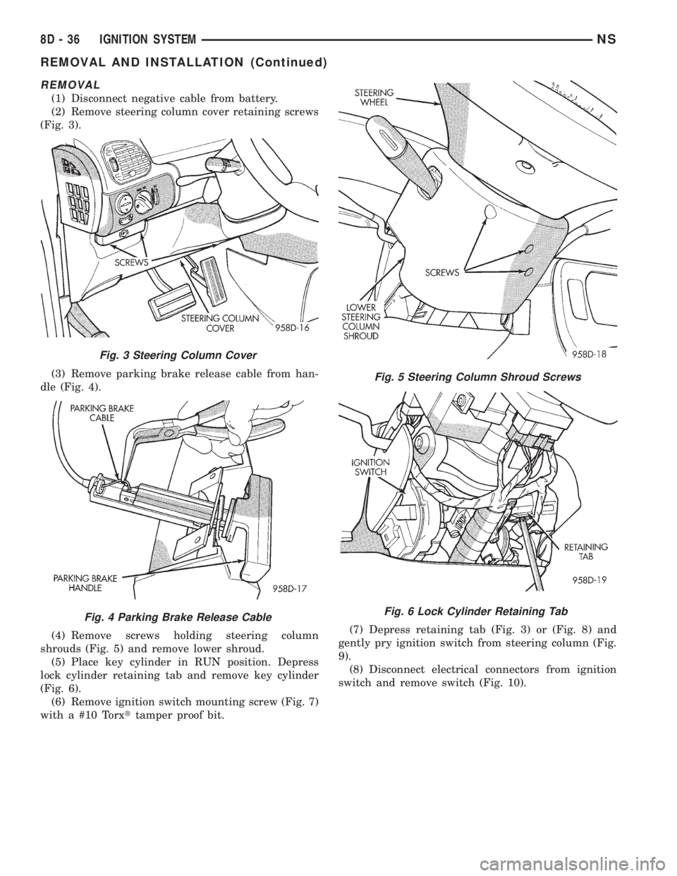
(1) Disconnect negative cable from battery.
(2) Remove steering column cover retaining screws
(Fig. 3).
(3) Remove parking brake release cable from han-
dle (Fig. 4).
(4) Remove screws holding steering column
shrouds (Fig. 5) and remove lower shroud.
(5) Place key cylinder in RUN position. Depress
lock cylinder retaining tab and remove key cylinder
(Fig. 6).
(6) Remove ignition switch mounting screw (Fig. 7)
with a #10 Torxttamper proof bit.(7) Depress retaining tab (Fig. 3) or (Fig. 8) and
gently pry ignition switch from steering column (Fig.
9).
(8) Disconnect electrical connectors from ignition
switch and remove switch (Fig. 10).
Fig. 3 Steering Column Cover
Fig. 4 Parking Brake Release Cable
Fig. 5 Steering Column Shroud Screws
Fig. 6 Lock Cylinder Retaining Tab
8D - 36 IGNITION SYSTEMNS
REMOVAL AND INSTALLATION (Continued)
Page 335 of 1938
INSTALLATION
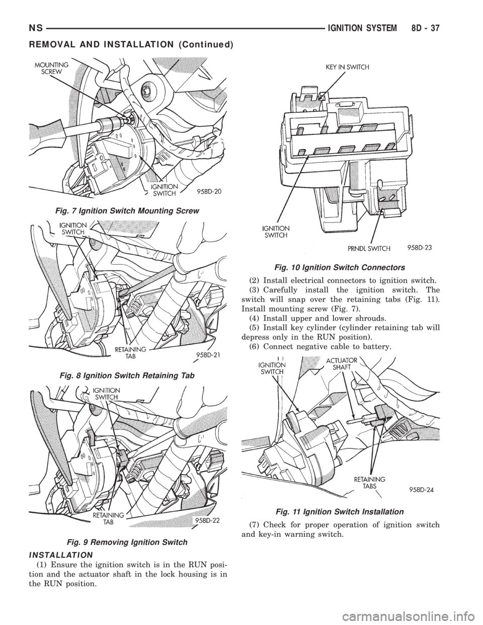
(1) Ensure the ignition switch is in the RUN posi-
tion and the actuator shaft in the lock housing is in
the RUN position.(2) Install electrical connectors to ignition switch.
(3) Carefully install the ignition switch. The
switch will snap over the retaining tabs (Fig. 11).
Install mounting screw (Fig. 7).
(4) Install upper and lower shrouds.
(5) Install key cylinder (cylinder retaining tab will
depress only in the RUN position).
(6) Connect negative cable to battery.
(7) Check for proper operation of ignition switch
and key-in warning switch.
Fig. 7 Ignition Switch Mounting Screw
Fig. 8 Ignition Switch Retaining Tab
Fig. 9 Removing Ignition Switch
Fig. 10 Ignition Switch Connectors
Fig. 11 Ignition Switch Installation
NSIGNITION SYSTEM 8D - 37
REMOVAL AND INSTALLATION (Continued)
Page 336 of 1938
LOCK KEY CYLINDER
REMOVAL
(1) Disconnect negative cable from battery.
(2) Remove steering column cover retaining screws
(Fig. 3).
(3) Remove screws holding steering column
shrouds (Fig. 5) and remove lower shroud.
(4) Place key cylinder in RUN position. Depress
lock cylinder retaining tab and remove key cylinder
(Fig. 6).
INSTALLATION
(1) Install key in lock cylinder. Turn key to run
position (retaining tab on lock cylinder can be
depressed).
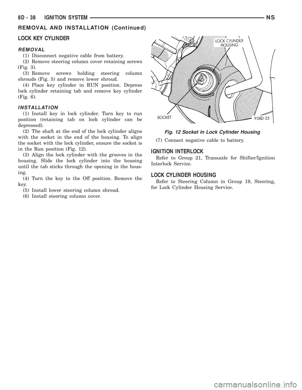
(2) The shaft at the end of the lock cylinder aligns
with the socket in the end of the housing. To align
the socket with the lock cylinder, ensure the socket is
in the Run position (Fig. 12).
(3) Align the lock cylinder with the grooves in the
housing. Slide the lock cylinder into the housing
until the tab sticks through the opening in the hous-
ing.
(4) Turn the key to the Off position. Remove the
key.
(5) Install lower steering column shroud.
(6) Install steering column cover.(7) Connect negative cable to battery.
IGNITION INTERLOCK
Refer to Group 21, Transaxle for Shifter/Ignition
Interlock Service.
LOCK CYLINDER HOUSING
Refer to Steering Column in Group 19, Steering,
for Lock Cylinder Housing Service.
Fig. 12 Socket in Lock Cylinder Housing
8D - 38 IGNITION SYSTEMNS
REMOVAL AND INSTALLATION (Continued)
Page 337 of 1938
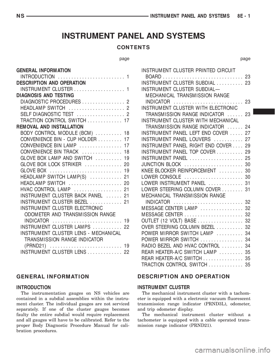
INSTRUMENT PANEL AND SYSTEMS
CONTENTS
page page
GENERAL INFORMATION
INTRODUCTION......................... 1
DESCRIPTION AND OPERATION
INSTRUMENT CLUSTER................... 1
DIAGNOSIS AND TESTING
DIAGNOSTIC PROCEDURES................ 2
HEADLAMP SWITCH..................... 2
SELF DIAGNOSTIC TEST.................. 2
TRACTION CONTROL SWITCH............. 17
REMOVAL AND INSTALLATION
BODY CONTROL MODULE (BCM).......... 18
CONVENIENCE BIN - CUP HOLDER......... 17
CONVENIENCE BIN LAMP................ 17
CONVENIENCE BIN TRACK............... 18
GLOVE BOX LAMP AND SWITCH.......... 19
GLOVE BOX LOCK STRIKER.............. 20
GLOVE BOX........................... 19
HEADLAMP SWITCH LAMP(S)............ 21
HEADLAMP SWITCH.................... 20
HVAC CONTROL LAMP.................. 21
INSTRUMENT CLUSTER BACK PANEL...... 21
INSTRUMENT CLUSTER BEZEL............ 21
INSTRUMENT CLUSTER ELECTRONIC
ODOMETER AND TRANSMISSION RANGE
INDICATOR.......................... 19
INSTRUMENT CLUSTER LAMPS........... 22
INSTRUMENT CLUSTER LENS - MECHANICAL
TRANSMISSION RANGE INDICATOR
(PRND21)........................... 19
INSTRUMENT CLUSTER LENS............. 22INSTRUMENT CLUSTER PRINTED CIRCUIT
BOARD.............................. 23
INSTRUMENT CLUSTER SUBDIAL.......... 23
INSTRUMENT CLUSTER SUBDIALÐ
MECHANICAL TRANSMISSION RANGE
INDICATOR.......................... 23
INSTRUMENT CLUSTER WITH ELECTRONIC
TRANSMISSION RANGE INDICATOR...... 23
INSTRUMENT CLUSTER WITH MECHANICAL
TRANSMISSION RANGE INDICATOR...... 24
INSTRUMENT PANEL LEFT END COVER..... 27
INSTRUMENT PANEL LOUVERS........... 27
INSTRUMENT PANEL RIGHT END COVER.... 29
INSTRUMENT PANEL TOP COVER.......... 29
INSTRUMENT PANEL.................... 25
JUNCTION BLOCK...................... 30
KNEE BLOCKER REINFORCEMENT......... 30
LOWER CONSOLE...................... 30
LOWER INSTRUMENT PANEL............. 31
LOWER STEERING COLUMN COVER........ 31
MECHANICAL TRANSMISSION RANGE
INDICATOR.......................... 32
MESSAGE CENTER LAMP................ 32
MESSAGE CENTER...................... 32
OUTLET (12 VOLT) BASE................. 32
OVER STEERING COLUMN BEZEL.......... 32
POWER MIRROR SWITCH LAMP.......... 34
POWER MIRROR SWITCH................ 34
RADIO BEZEL AND HVAC CONTROL........ 34
REAR HEATER-A/C SWITCH LAMP......... 35
REAR HEATER-A/C SWITCH............... 35
TRACTION CONTROL SWITCH............. 35
GENERAL INFORMATION
INTRODUCTION
The instrumentation gauges on NS vehicles are
contained in a subdial assemblies within the instru-
ment cluster. The individual gauges are not serviced
separately. If one of the cluster gauges becomes
faulty the entire subdial would require replacement
and all gauges will have to be calibrated. Refer to the
proper Body Diagnostic Procedure Manual for cali-
bration procedures.
DESCRIPTION AND OPERATION
INSTRUMENT CLUSTER
The mechanical instrument cluster with a tachom-
eter is equipped with a electronic vacuum fluorescent
transmission range indicator (PRND3L), odometer,
and trip odometer display.
The mechanical instrument cluster without a
tachometer is equipped with a cable operated trans-
mission range indicator (PRND21).
NSINSTRUMENT PANEL AND SYSTEMS 8E - 1
Page 338 of 1938
The instrument cluster is equipped with the follow-
ing warning lamps.
²Lift Gate Ajar
²Low Fuel Level
²Low Windshield Washer Fluid Level
²Cruise
²Battery Voltage
²Fasten Seat Belt
²Door Ajar
DIAGNOSIS AND TESTING
DIAGNOSTIC PROCEDURES
NS vehicle instrument clusters are equipped with a
self diagnostic test feature to help identify electronic
problems. Prior to any test, perform Self Diagnostic
Test. The self diagnostic system monitors the CCD
bus messages. If an electronic problem occurs, a
Diagnostic Trouble Code (DTC) will be displayed in
the odometer window of the cluster.
The following CCD bus messages are continuously
monitored by the diagnostic system:
²Body Control Module
²Powertrain Control Module
²Transmission Control Module, if equipped
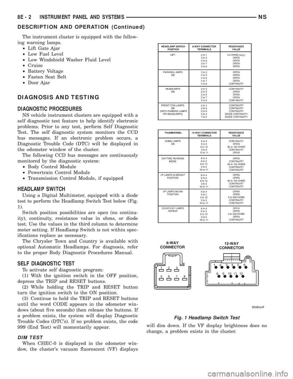
HEADLAMP SWITCH
Using a Digital Multimeter, equipped with a diode
test to perform the Headlamp Switch Test below (Fig.
1).
Switch position possibilities are open (no continu-
ity), continuity, resistance value in ohms, or diode
test. Use the values in the third column to determine
meter setting. If Headlamp Switch is not within spec-
ifications replace as necessary.
The Chrysler Town and Country is available with
optional Automatic Headlamps. For diagnosis, refer
to the proper Body Diagnostic Procedures Manual.
SELF DIAGNOSTIC TEST
To activate self diagnostic program:
(1) With the ignition switch in the OFF position,
depress the TRIP and RESET buttons.
(2) While holding the TRIP and RESET button
turn the ignition switch to the ON position.
(3) Continue to hold the TRIP and RESET buttons
until the word CODE appears in the odometer win-
dows (about five seconds) then release the buttons. If
a problem exists, the system will display Diagnostic
Trouble Codes (DTC's). If no problem exists, the code
999 (End Test) will momentarily appear.
DIM TEST
When CHEC-0 is displayed in the odometer win-
dow, the cluster's vacuum fluorescent (VF) displayswill dim down. If the VF display brightness does no
change, a problem exists in the cluster.
Fig. 1 Headlamp Switch Test
8E - 2 INSTRUMENT PANEL AND SYSTEMSNS
DESCRIPTION AND OPERATION (Continued)
Page 339 of 1938
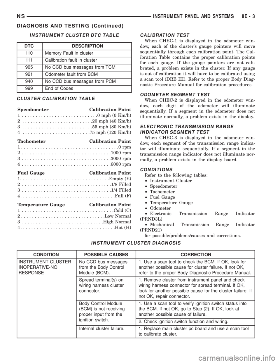
CLUSTER CALIBRATION TABLE
Speedometer Calibration Point
1 ............................0mph(0Km/h)
2 ..........................20mph(40Km/h)
3 ..........................55mph(80Km/h)
4 .........................75mph(120 Km/h)
Tachometer Calibration Point
1....................................0rpm
2 .................................1000 rpm
3 .................................3000 rpm
4 .................................6000 rpm
Fuel Gauge Calibration Point
1.................................Empty (E)
2 .................................1/8 Filled
3 .................................1/4 Filled
4...................................Full (F)
Temperature Gauge Calibration Point
1 ..................................Cold (C)
2...............................Low Normal
3 ..............................High Normal
4...................................Hot (H)
CALIBRATION TEST
When CHEC-1 is displayed in the odometer win-
dow, each of the cluster's gauge pointers will move
sequentially through each calibration point. The Cal-
ibration Table contains the proper calibration points
for each gauge. If the gauge pointers are not cali-
brated, a problem exists in the cluster. If any gauge
is out of calibration it will have to be calibrated using
a scan tool (DRB III). Refer to the proper Body Diag-
nostic Procedure Manual for calibration procedures.
ODOMETER SEGMENT TEST
When CHEC-2 is displayed in the odometer win-
dow, each digit of the odometer will illuminate
sequentially. If a segment in the odometer does not
illuminate normally, a problem exists in the display.
ELECTRONIC TRANSMISSION RANGE
INDICATOR SEGMENT TEST
When CHEC-3 is displayed in the odometer win-
dow, each segment of the transmission range indica-
tor will illuminate sequentially. If a segment in the
transmission range indicator does not illuminate nor-
mally, a problem exists in the display board.
CONDITIONS
Refer to the following tables:
²Instrument Cluster
²Speedometer
²Tachometer
²Fuel Gauge
²Temperature Gauge
²Odometer
²Electronic Transmission Range Indicator
(PRND3L)
²Mechanical Transmission Range Indicator
(PRND21)
for possible/problems/causes and corrections.
INSTRUMENT CLUSTER DTC TABLE
DTC DESCRIPTION
110 Memory Fault in cluster
111 Calibration fault in cluster
905 No CCD bus messages from TCM
921 Odometer fault from BCM
940 No CCD bus messages from PCM
999 End of Codes
INSTRUMENT CLUSTER DIAGNOSIS
CONDITION POSSIBLE CAUSES CORRECTION
INSTRUMENT CLUSTER
INOPERATIVE-NO
RESPONSENo CCD bus messages
from the Body Control
Module (BCM).1. Use a scan tool to check the BCM. If OK, look for
another possible cause for cluster failure. If not OK,
refer to the proper Body Diagnostic Procedure Manual.
Spread terminal(s) on
wiring harness cluster
connector.1. Remove cluster from instrument panel and check
wiring harness connector for spread terminal. If OK,
look for another possible cause for the cluster failure. If
not OK, repair connector.
Body Control Module
(BCM) is not receiving
proper input from the
ignition switch.1. Use a scan tool to verify ignition switch status into
the BCM. If not OK, go to Step (2). If OK, look at
another possible cause of failure.
2. Check ignition switch function and wiring.
Internal cluster failure. 1. Replace main cluster pc board and use a scan tool
to calibrate cluster.
NSINSTRUMENT PANEL AND SYSTEMS 8E - 3
DIAGNOSIS AND TESTING (Continued)
Page 340 of 1938
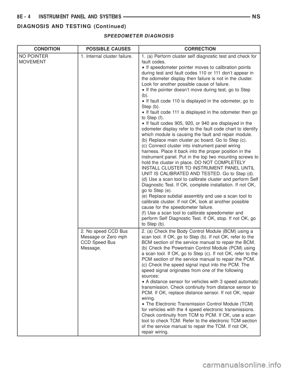
SPEEDOMETER DIAGNOSIS
CONDITION POSSIBLE CAUSES CORRECTION
NO POINTER
MOVEMENT1. Internal cluster failure. 1. (a) Perform cluster self diagnostic test and check for
fault codes.
²If speedometer pointer moves to calibration points
during test and fault codes 110 or 111 don't appear in
the odometer display then failure is not in the cluster.
Look for another possible cause of failure.
²If the pointer doesn't move during test, go to Step
(b).
²If fault code 110 is displayed in the odometer, go to
Step (b).
²If fault code 111 is displayed in the odometer then go
to Step (f).
²If fault codes 905, 920, or 940 are displayed in the
odometer display refer to the fault code chart to identify
which module is causing the fault and repair module.
(b) Replace main cluster pc board. Go to Step (c).
(c) Connect cluster into instrument panel wiring
harness. Place it back into the proper position in the
instrument panel. Put in the top two mounting screws to
hold the cluster in place. DO NOT COMPLETELY
INSTALL CLUSTER TO INSTRUMENT PANEL UNTIL
UNIT IS CALIBRATED AND TESTED. Go to Step (d).
(d) Use a scan tool to calibrate cluster and perform Self
Diagnostic Test. If OK, complete installation. If not OK,
go to Step (e).
(e) Replace subdial assembly and use a scan tool to
calibrate cluster. If not OK, look at another possible
cause for the speedometer failure.
(f) Use a scan tool to calibrate speedometer and
perform Self Diagnostic Test. If OK, stop. If not OK, go
to Step (b).
2. No speed CCD Bus
Message or Zero mph
CCD Speed Bus
Message.2. (a) Check the Body Control Module (BCM) using a
scan tool. If OK, go to Step (b). If not OK, refer to the
BCM section of the service manual to repair the BCM.
(b) Check the Powertrain Control Module (PCM) using
a scan tool. If OK, go to Step (c). If not OK, refer to the
PCM section of the service manual to repair the PCM.
(c) Check the speed signal input into the PCM. The
speed signal originates from one of the following
sources:
²A distance sensor for vehicles with 3 speed automatic
transmission. Check continuity from distance sensor to
PCM. If OK, replace distance sensor. If not OK, repair
wiring.
²The Electronic Transmission Control Module (TCM)
for vehicles with the 4 speed electronic transmissions.
Check continuity from TCM to PCM. If OK, use a scan
tool to check TCM. Refer to the electronic TCM section
of the service manual to repair the TCM. If not OK,
repair wiring.
8E - 4 INSTRUMENT PANEL AND SYSTEMSNS
DIAGNOSIS AND TESTING (Continued)