clock CHRYSLER VOYAGER 1996 Manual PDF
[x] Cancel search | Manufacturer: CHRYSLER, Model Year: 1996, Model line: VOYAGER, Model: CHRYSLER VOYAGER 1996Pages: 1938, PDF Size: 55.84 MB
Page 995 of 1938

CONNECTOR/GROUND LOCATIONS
For items not shown in this section a N/S is placed
in the Fig. column.
Component/
GroundColor Location Fig.
A/C
Compressor
ClutchBK Top of A/C
Compressor5, 6, 7,
8, 9
A/C-Heater
Control Module
C1NAT Rear of Control 11
A/C-Heater
Control Module
C2BK Rear of Control 11
A/C Pressure
TransducerGY RT Side Cowl 3
A/C Zone Door
ActuatorNAT LT Side of
HVAC15
Airbag Control
Module C1YL Rear of I.P.
Center Stack12
Airbag Contol
Module C2BK Rear of I.P.
Center Stack12
All Wheel Drive
SolenoidBK Near Fuel Tank 20
Ambient
Temperature
SensorGY On Radiator
Closure Panel4
Ash Receiver
LampRD At Lamp 10
Automatic
Day/Night MirrorBK At Mirror 17
B01 BK RT Kick Panel 18
B02 BK RT Kick Panel 18
B03 BK LT Kick Panel 18
B09 BK Under Seat 16
B17 BK LT Quarter
Panel21
B23 BK RT of Steering
Column13
B33 BK LT Frame Rail 2
B56 BK Under Seat 16
B70 LT/GY LT Frame Rail 2
B75 BL Bottom of RT
B-Pillar14
B98 BK Rear of RT Tail
LampN/SComponent/
GroundColor Location Fig.
B99 BK Rear of LT Tail
LampN/S
B120 BK LT Kick Panel N/S
Backup Lamp
Switch (M/T)BK On
Transmission5, 6, 8
Blend Door
ActuatorNAT LT Side of
HVAC15
Body Control
Module C1NAT On Junction
Block12
Body Control
Module C2NAT On Junction
Block12
Brake Pressure
SwitchBK On Master
Cylinder2
C19 At Top Center
of Windshield17
C20 Bottom of RT
B-PillarN/S
Camshaft
Position Sensor
2.4LBK Rear of
Cylinder Head6, 7
Camshaft
Position Sensor
3.3L, 3.8LBK RT Side of
Engine9
Center Dome
LampBK At Lamp N/S
CHMSL RD Rear of CHMSL 23
Clockspring C1 YL Rear of
Clockspring11
Clockspring C2 NAT Rear of
Clockspring11
Clutch Switch BK Top of Clutch
Pedal13
Controller
Anti-Lock BrakeBK LT Side of
Engine
CompartmentN/S
Crankshaft
Position SensorBK Rear of Engine 5, 6, 7,
9
D01 BK On Kick Panel 19
D02 BK On Kick Panel 19
Data Link
ConnectorBK LT of Steering
Column12
NS/GS8W - 90 CONNECTOR/GROUND LOCATIONS 8W - 90 - 31
DESCRIPTION AND OPERATION (Continued)
Page 1082 of 1938
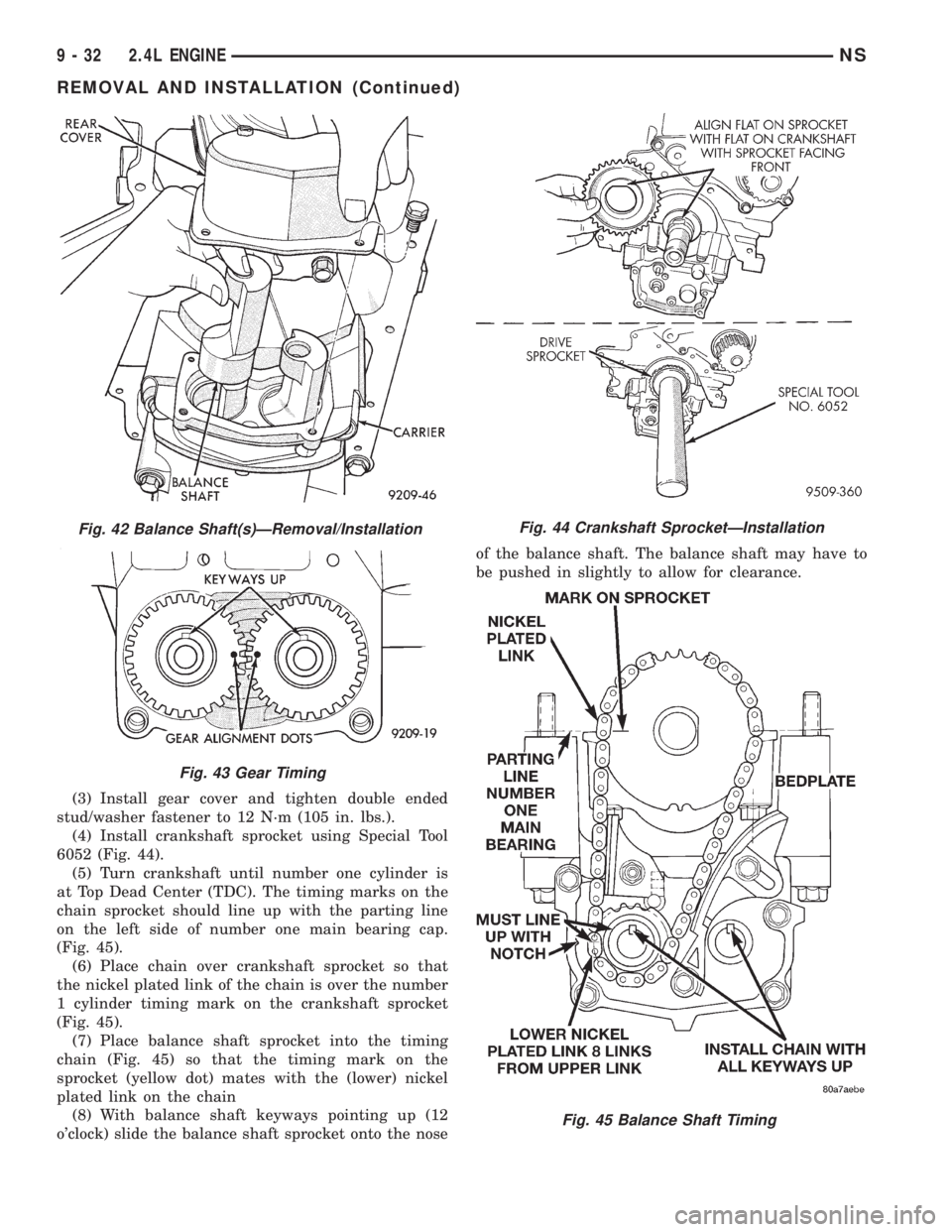
(3) Install gear cover and tighten double ended
stud/washer fastener to 12 N´m (105 in. lbs.).
(4) Install crankshaft sprocket using Special Tool
6052 (Fig. 44).
(5) Turn crankshaft until number one cylinder is
at Top Dead Center (TDC). The timing marks on the
chain sprocket should line up with the parting line
on the left side of number one main bearing cap.
(Fig. 45).
(6) Place chain over crankshaft sprocket so that
the nickel plated link of the chain is over the number
1 cylinder timing mark on the crankshaft sprocket
(Fig. 45).
(7) Place balance shaft sprocket into the timing
chain (Fig. 45) so that the timing mark on the
sprocket (yellow dot) mates with the (lower) nickel
plated link on the chain
(8) With balance shaft keyways pointing up (12
o'clock) slide the balance shaft sprocket onto the noseof the balance shaft. The balance shaft may have to
be pushed in slightly to allow for clearance.
Fig. 42 Balance Shaft(s)ÐRemoval/Installation
Fig. 43 Gear Timing
Fig. 44 Crankshaft SprocketÐInstallation
Fig. 45 Balance Shaft Timing
9 - 32 2.4L ENGINENS
REMOVAL AND INSTALLATION (Continued)
Page 1088 of 1938
(6) Lower vehicle and remove upper timing belt
cover fasteners and remove cover.
(7) Remove right engine mount and support
bracket. Refer to Removal and Installation procedure
in this section.
CAUTION: When aligning crankshaft and camshaft
timing marks always rotate engine from crankshaft.
Camshaft should not be rotated after timing belt is
removed. Damage to valve components may occur.
Always align timing marks before removing timing
belt.
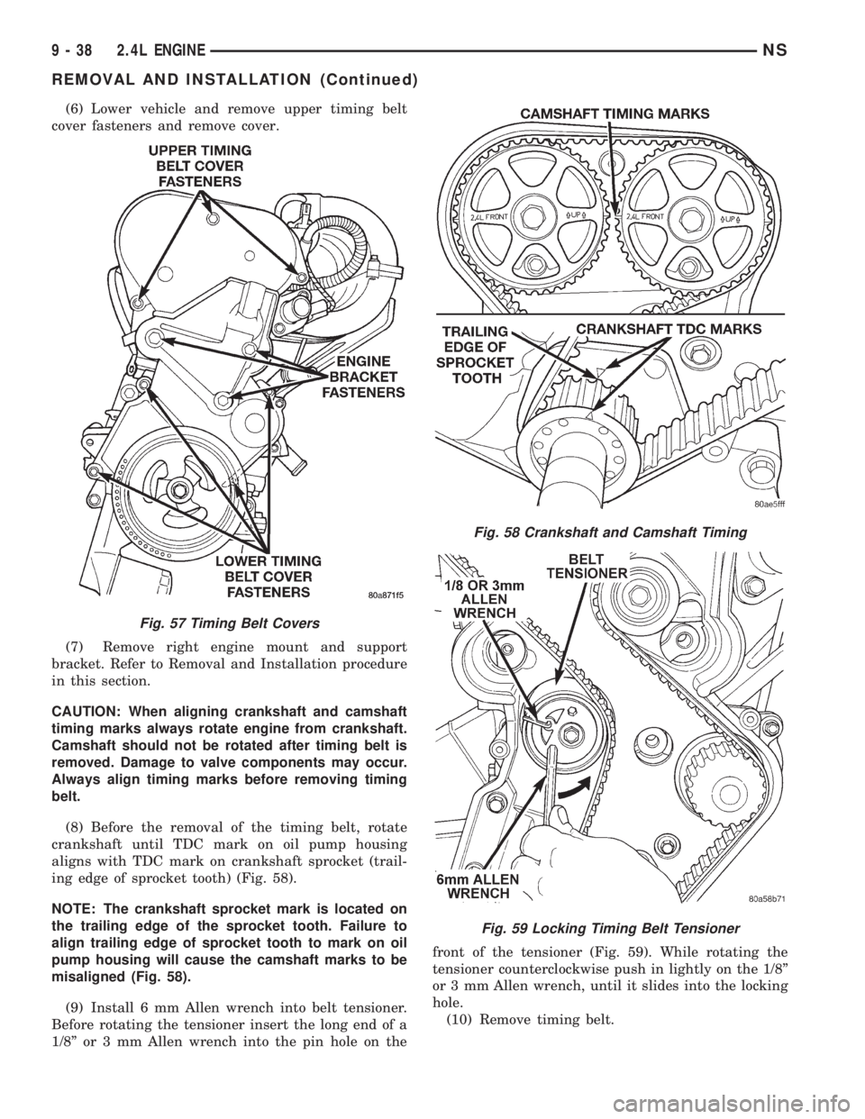
(8) Before the removal of the timing belt, rotate
crankshaft until TDC mark on oil pump housing
aligns with TDC mark on crankshaft sprocket (trail-
ing edge of sprocket tooth) (Fig. 58).
NOTE: The crankshaft sprocket mark is located on
the trailing edge of the sprocket tooth. Failure to
align trailing edge of sprocket tooth to mark on oil
pump housing will cause the camshaft marks to be
misaligned (Fig. 58).
(9) Install 6 mm Allen wrench into belt tensioner.
Before rotating the tensioner insert the long end of a
1/8º or 3 mm Allen wrench into the pin hole on thefront of the tensioner (Fig. 59). While rotating the
tensioner counterclockwise push in lightly on the 1/8º
or 3 mm Allen wrench, until it slides into the locking
hole.
(10) Remove timing belt.
Fig. 57 Timing Belt Covers
Fig. 58 Crankshaft and Camshaft Timing
Fig. 59 Locking Timing Belt Tensioner
9 - 38 2.4L ENGINENS
REMOVAL AND INSTALLATION (Continued)
Page 1089 of 1938
CAUTION: If timing belt was damaged due to incor-
rect tracking (alignment), the belt tensioner assem-
bly must be replace. Refer to Timing Belt Tensioner
Assembly Removal and Installation procedure out-
lined in this section.
INSTALLATION
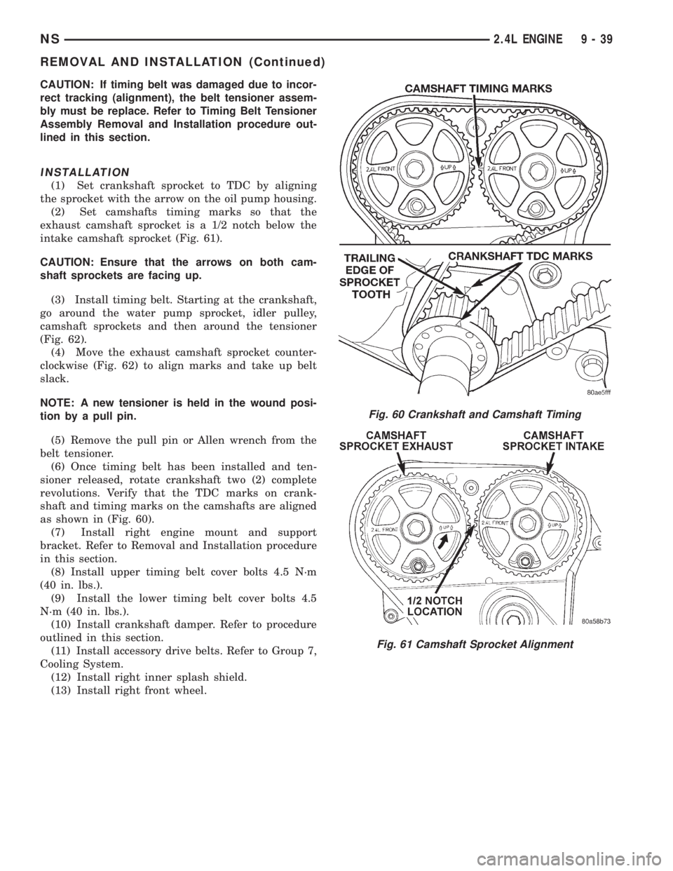
(1) Set crankshaft sprocket to TDC by aligning
the sprocket with the arrow on the oil pump housing.
(2) Set camshafts timing marks so that the
exhaust camshaft sprocket is a 1/2 notch below the
intake camshaft sprocket (Fig. 61).
CAUTION: Ensure that the arrows on both cam-
shaft sprockets are facing up.
(3) Install timing belt. Starting at the crankshaft,
go around the water pump sprocket, idler pulley,
camshaft sprockets and then around the tensioner
(Fig. 62).
(4) Move the exhaust camshaft sprocket counter-
clockwise (Fig. 62) to align marks and take up belt
slack.
NOTE: A new tensioner is held in the wound posi-
tion by a pull pin.
(5) Remove the pull pin or Allen wrench from the
belt tensioner.
(6) Once timing belt has been installed and ten-
sioner released, rotate crankshaft two (2) complete
revolutions. Verify that the TDC marks on crank-
shaft and timing marks on the camshafts are aligned
as shown in (Fig. 60).
(7) Install right engine mount and support
bracket. Refer to Removal and Installation procedure
in this section.
(8) Install upper timing belt cover bolts 4.5 N´m
(40 in. lbs.).
(9) Install the lower timing belt cover bolts 4.5
N´m (40 in. lbs.).
(10) Install crankshaft damper. Refer to procedure
outlined in this section.
(11) Install accessory drive belts. Refer to Group 7,
Cooling System.
(12) Install right inner splash shield.
(13) Install right front wheel.
Fig. 60 Crankshaft and Camshaft Timing
Fig. 61 Camshaft Sprocket Alignment
NS2.4L ENGINE 9 - 39
REMOVAL AND INSTALLATION (Continued)
Page 1097 of 1938
(7) Install main bearing bedplate to engine block
bolts 11, 17 and 20 finger tight. Tighten these bolts
down together until the bedplate contacts the cylin-
der block.
(8) To ensure correct thrust bearing alignment per-
form the following steps:
²Step 1: Rotate crankshaft until number 4 pis-
ton is at TDC.
²Step 2: Move crankshaft rearward to limits of
travel.
²Step 3: Then, move crankshaft forward to lim-
its of travel.
²Step 4: Wedge an appropraite tool between the
rear of the cylinder block(NOT BED PLATE)and
the rear crankshaft counterweight. This will hold the
crankshaft in it's furthest forward position.
²Step 5: Install and tighten bolts (1-10) in
sequence shown in (Fig. 84) to 41 Nzm (30 ft. lbs.).
²Step 6: Remove wedge tool used to hold crank-
shaft.
(9) Tighten bolts (1-10) again to 41 Nzm (30 ft. lbs)
+ 1/4 turn in sequence shown in (Fig. 84).
(10) Install main bearing bedplate to engine block
bolts (11-20), and torque each bolt to 28 Nzm (20 ft.
lbs.) in sequence shown in (Fig. 84).
(11) After the main bearing bedplate is installed,
check the crankshaft turning torque. The turning
torque should not exceed 5.6 Nzm (50 in. lbs.).
OIL FILTER
CAUTION: When servicing the oil filter avoid
deforming the filter can by installing the remove/in-
stall tool band strap against the can to base lock
seam. The lock seam joining the can to the base is
reinforced by the base plate.(1) Turn counterclockwise to remove.
(2) To install, lubricate new filter gasket. Check
filter mounting surface. The surface must be smooth,
flat and free of debris or old pieces of rubber. Screw
filter on until the gasket contacts base. Tighten to 21
N´m (15 ft. lbs.).
OIL PUMP
REMOVAL
(1) Disconnect negative cable from battery.
(2) Remove Timing Belt. Refer to procedure out-
lined in this section.
(3) Remove Oil Pan. Refer to procedure outlined in
this section.
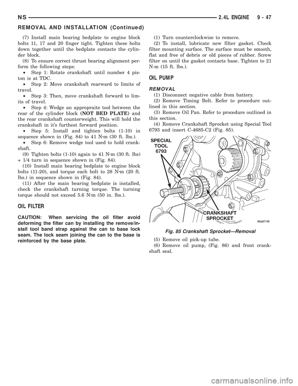
(4) Remove Crankshaft Sprocket using Special Tool
6793 and insert C-4685-C2 (Fig. 85).
(5) Remove oil pick-up tube.
(6) Remove oil pump, (Fig. 86) and front crank-
shaft seal.
Fig. 85 Crankshaft SprocketÐRemoval
NS2.4L ENGINE 9 - 47
REMOVAL AND INSTALLATION (Continued)
Page 1126 of 1938
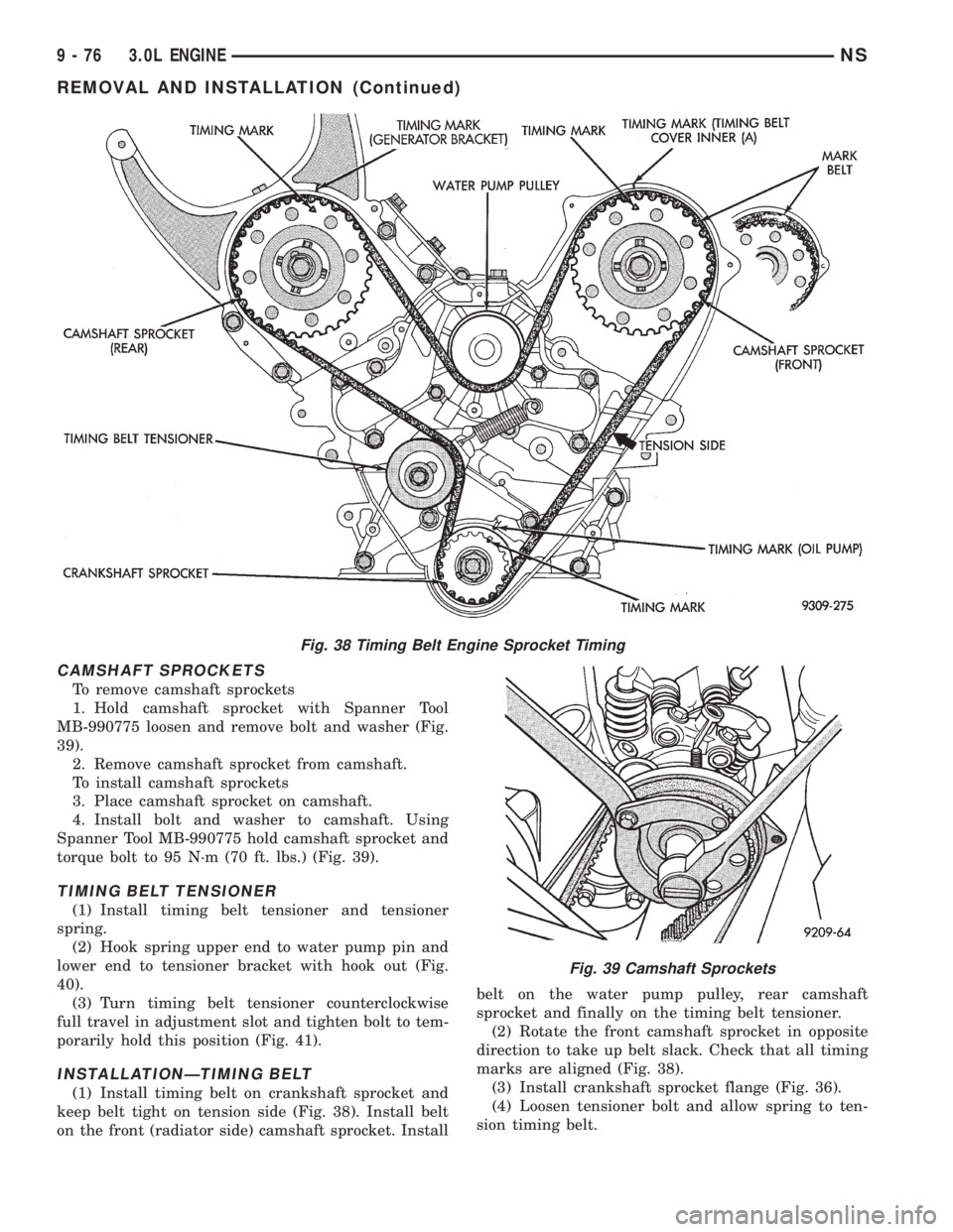
CAMSHAFT SPROCKETS
To remove camshaft sprockets
1. Hold camshaft sprocket with Spanner Tool
MB-990775 loosen and remove bolt and washer (Fig.
39).
2. Remove camshaft sprocket from camshaft.
To install camshaft sprockets
3. Place camshaft sprocket on camshaft.
4. Install bolt and washer to camshaft. Using
Spanner Tool MB-990775 hold camshaft sprocket and
torque bolt to 95 N´m (70 ft. lbs.) (Fig. 39).
TIMING BELT TENSIONER
(1) Install timing belt tensioner and tensioner
spring.
(2) Hook spring upper end to water pump pin and
lower end to tensioner bracket with hook out (Fig.
40).
(3) Turn timing belt tensioner counterclockwise
full travel in adjustment slot and tighten bolt to tem-
porarily hold this position (Fig. 41).
INSTALLATIONÐTIMING BELT
(1) Install timing belt on crankshaft sprocket and
keep belt tight on tension side (Fig. 38). Install belt
on the front (radiator side) camshaft sprocket. Installbelt on the water pump pulley, rear camshaft
sprocket and finally on the timing belt tensioner.
(2) Rotate the front camshaft sprocket in opposite
direction to take up belt slack. Check that all timing
marks are aligned (Fig. 38).
(3) Install crankshaft sprocket flange (Fig. 36).
(4) Loosen tensioner bolt and allow spring to ten-
sion timing belt.
Fig. 38 Timing Belt Engine Sprocket Timing
Fig. 39 Camshaft Sprockets
9 - 76 3.0L ENGINENS
REMOVAL AND INSTALLATION (Continued)
Page 1127 of 1938
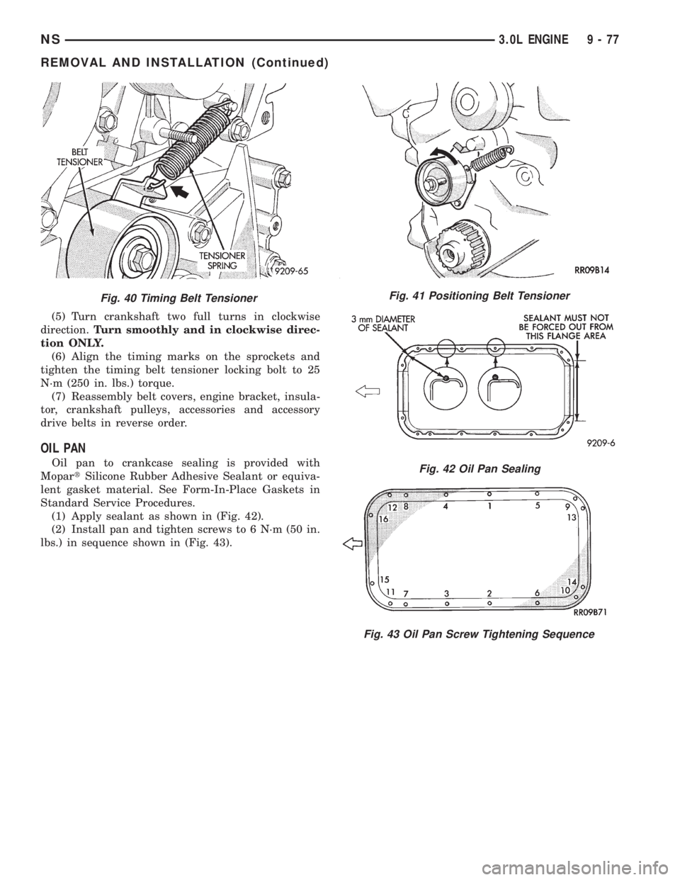
(5) Turn crankshaft two full turns in clockwise
direction.Turn smoothly and in clockwise direc-
tion ONLY.
(6) Align the timing marks on the sprockets and
tighten the timing belt tensioner locking bolt to 25
N´m (250 in. lbs.) torque.
(7) Reassembly belt covers, engine bracket, insula-
tor, crankshaft pulleys, accessories and accessory
drive belts in reverse order.
OIL PAN
Oil pan to crankcase sealing is provided with
MopartSilicone Rubber Adhesive Sealant or equiva-
lent gasket material. See Form-In-Place Gaskets in
Standard Service Procedures.
(1) Apply sealant as shown in (Fig. 42).
(2) Install pan and tighten screws to 6 N´m (50 in.
lbs.) in sequence shown in (Fig. 43).
Fig. 41 Positioning Belt Tensioner
Fig. 42 Oil Pan Sealing
Fig. 43 Oil Pan Screw Tightening Sequence
Fig. 40 Timing Belt Tensioner
NS3.0L ENGINE 9 - 77
REMOVAL AND INSTALLATION (Continued)
Page 1134 of 1938
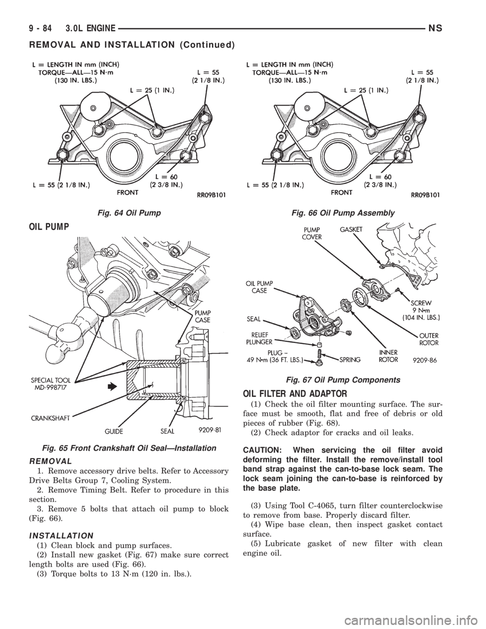
OIL PUMP
REMOVAL
1. Remove accessory drive belts. Refer to Accessory
Drive Belts Group 7, Cooling System.
2. Remove Timing Belt. Refer to procedure in this
section.
3. Remove 5 bolts that attach oil pump to block
(Fig. 66).
INSTALLATION
(1) Clean block and pump surfaces.
(2) Install new gasket (Fig. 67) make sure correct
length bolts are used (Fig. 66).
(3) Torque bolts to 13 N´m (120 in. lbs.).
OIL FILTER AND ADAPTOR
(1) Check the oil filter mounting surface. The sur-
face must be smooth, flat and free of debris or old
pieces of rubber (Fig. 68).
(2) Check adaptor for cracks and oil leaks.
CAUTION: When servicing the oil filter avoid
deforming the filter. Install the remove/install tool
band strap against the can-to-base lock seam. The
lock seam joining the can-to-base is reinforced by
the base plate.
(3) Using Tool C-4065, turn filter counterclockwise
to remove from base. Properly discard filter.
(4) Wipe base clean, then inspect gasket contact
surface.
(5) Lubricate gasket of new filter with clean
engine oil.
Fig. 64 Oil Pump
Fig. 65 Front Crankshaft Oil SealÐInstallation
Fig. 66 Oil Pump Assembly
Fig. 67 Oil Pump Components
9 - 84 3.0L ENGINENS
REMOVAL AND INSTALLATION (Continued)
Page 1146 of 1938
NOTE: Worn valve guides or cocked springs are
sometimes mistaken for noisy tappets. If such is
the case, noise may be dampened by applying side
thrust on the valve spring. If noise is not apprecia-
bly reduced, it can be assumed the noise is in the
tappet. Inspect the rocker arm push rod sockets
and push rod ends for wear.
Valve tappet noise ranges from light noise to a
heavy click. A light noise is usually caused by exces-
sive leak-down around the unit plunger which will
necessitate replacing the tappet, or by the plunger
partially sticking in the tappet body cylinder. A heavy
click is caused either by a tappet check valve not
seating, or by foreign particles becoming wedged
between the plunger and the tappet body causing the
plunger to stick in the down position. This heavy
click will be accompanied by excessive clearance
between the valve stem and rocker arm as valve
closes. In either case, tappet assembly should be
removed for inspection and cleaning.
CHECKING ENGINE OIL PRESSURE
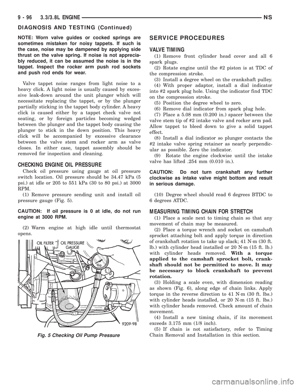
Check oil pressure using gauge at oil pressure
switch location. Oil pressure should be 34.47 kPa (5
psi.) at idle or 205 to 551 kPa (30 to 80 psi.) at 3000
RPM.
(1) Remove pressure sending unit and install oil
pressure gauge (Fig. 5).
CAUTION: If oil pressure is 0 at idle, do not run
engine at 3000 RPM.
(2) Warm engine at high idle until thermostat
opens.
SERVICE PROCEDURES
VALVE TIMING
(1) Remove front cylinder head cover and all 6
spark plugs.
(2) Rotate engine until the #2 piston is at TDC of
the compression stroke.
(3) Install a degree wheel on the crankshaft pulley.
(4) With proper adaptor, install a dial indicator
into #2 spark plug hole. Using the indicator find TDC
on the compression stroke.
(5) Position the degree wheel to zero.
(6) Remove dial indicator from spark plug hole.
(7) Place a 5.08 mm (0.200 in.) spacer between the
valve stem tip of #2 intake valve and rocker arm pad.
Allow tappet to bleed down to give a solid tappet
effect.
(8) Install a dial indicator so plunger contacts the
#2 intake valve spring retainer as nearly perpendic-
ular as possible. Zero the indicator.
(9) Rotate the engine clockwise until the intake
valve has lifted .254 mm (0.010 in.).
CAUTION: Do not turn crankshaft any further
clockwise as intake valve might bottom and result
in serious damage.
(10) Degree wheel should read 6 degrees BTDC to
6 degrees ATDC.
MEASURING TIMING CHAIN FOR STRETCH
(1) Place a scale next to timing chain so that any
movement of chain may be measured.
(2) Place a torque wrench and socket on camshaft
sprocket attaching bolt and apply torque in direction
of crankshaft rotation to take up slack; 41 N´m (30 ft.
lb.) with cylinder head installed or 20 N´m (15 ft. lb.)
with cylinder heads removed.With a torque
applied to the camshaft sprocket bolt, crank-
shaft should not be permitted to move. It may
be necessary to block crankshaft to prevent
rotation.
(3) Holding a scale even, with dimension reading
as shown (Fig. 6), along edge of chain links. Apply
torque in the reverse direction to 41 N´m (30 ft. lbs.)
with cylinder heads installed, or 20 N´m (15 ft. lbs.)
with cylinder heads removed. Check amount of chain
movement.
(4) Install a new timing chain, if its movement
exceeds 3.175 mm (1/8 inch).
(5) If chain is not satisfactory, refer to Timing
Chain Removal and Installation in this section.
Fig. 5 Checking Oil Pump Pressure
9 - 96 3.3/3.8L ENGINENS
DIAGNOSIS AND TESTING (Continued)
Page 1162 of 1938
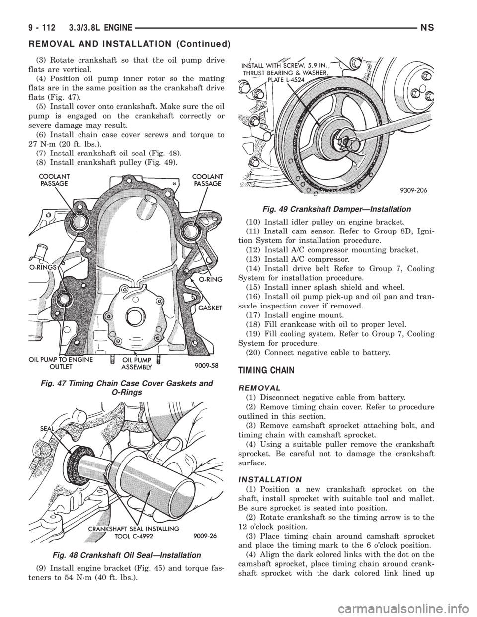
(3) Rotate crankshaft so that the oil pump drive
flats are vertical.
(4) Position oil pump inner rotor so the mating
flats are in the same position as the crankshaft drive
flats (Fig. 47).
(5) Install cover onto crankshaft. Make sure the oil
pump is engaged on the crankshaft correctly or
severe damage may result.
(6) Install chain case cover screws and torque to
27 N´m (20 ft. lbs.).
(7) Install crankshaft oil seal (Fig. 48).
(8) Install crankshaft pulley (Fig. 49).
(9) Install engine bracket (Fig. 45) and torque fas-
teners to 54 N´m (40 ft. lbs.).(10) Install idler pulley on engine bracket.
(11) Install cam sensor. Refer to Group 8D, Igni-
tion System for installation procedure.
(12) Install A/C compressor mounting bracket.
(13) Install A/C compressor.
(14) Install drive belt Refer to Group 7, Cooling
System for installation procedure.
(15) Install inner splash shield and wheel.
(16) Install oil pump pick-up and oil pan and tran-
saxle inspection cover if removed.
(17) Install engine mount.
(18) Fill crankcase with oil to proper level.
(19) Fill cooling system. Refer to Group 7, Cooling
System for procedure.
(20) Connect negative cable to battery.
TIMING CHAIN
REMOVAL
(1) Disconnect negative cable from battery.
(2) Remove timing chain cover. Refer to procedure
outlined in this section.
(3) Remove camshaft sprocket attaching bolt, and
timing chain with camshaft sprocket.
(4) Using a suitable puller remove the crankshaft
sprocket. Be careful not to damage the crankshaft
surface.
INSTALLATION
(1) Position a new crankshaft sprocket on the
shaft, install sprocket with suitable tool and mallet.
Be sure sprocket is seated into position.
(2) Rotate crankshaft so the timing arrow is to the
12 o'clock position.
(3) Place timing chain around camshaft sprocket
and place the timing mark to the 6 o'clock position.
(4) Align the dark colored links with the dot on the
camshaft sprocket, place timing chain around crank-
shaft sprocket with the dark colored link lined up
Fig. 47 Timing Chain Case Cover Gaskets and
O-Rings
Fig. 48 Crankshaft Oil SealÐInstallation
Fig. 49 Crankshaft DamperÐInstallation
9 - 112 3.3/3.8L ENGINENS
REMOVAL AND INSTALLATION (Continued)