warning light CHRYSLER VOYAGER 1996 Owner's Guide
[x] Cancel search | Manufacturer: CHRYSLER, Model Year: 1996, Model line: VOYAGER, Model: CHRYSLER VOYAGER 1996Pages: 1938, PDF Size: 55.84 MB
Page 1308 of 1938
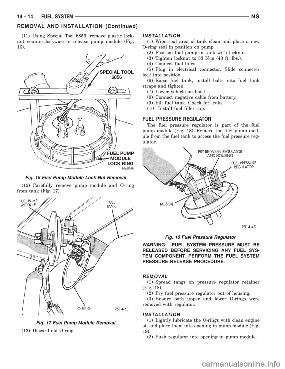
(11) Using Special Tool 6856, remove plastic lock-
nut counterclockwise to release pump module (Fig.
16).
(12) Carefully remove pump module and O-ring
from tank (Fig. 17).
(13) Discard old O-ring.INSTALLATION
(1) Wipe seal area of tank clean and place a new
O-ring seal in position on pump.
(2) Position fuel pump in tank with locknut.
(3) Tighten locknut to 53 N´m (43 ft. lbs.).
(4) Connect fuel lines.
(5) Plug in electrical connector. Slide connector
lock into position.
(6) Raise fuel tank, install bolts into fuel tank
straps and tighten.
(7) Lower vehicle on hoist.
(8) Connect negative cable from battery.
(9) Fill fuel tank. Check for leaks.
(10) Install fuel filler cap.
FUEL PRESSURE REGULATOR
The fuel pressure regulator is part of the fuel
pump module (Fig. 18). Remove the fuel pump mod-
ule from the fuel tank to access the fuel pressure reg-
ulator.
WARNING: FUEL SYSTEM PRESSURE MUST BE
RELEASED BEFORE SERVICING ANY FUEL SYS-
TEM COMPONENT. PERFORM THE FUEL SYSTEM
PRESSURE RELEASE PROCEDURE.
REMOVAL
(1) Spread tangs on pressure regulator retainer
(Fig. 18).
(2) Pry fuel pressure regulator out of housing.
(3) Ensure both upper and lower O-rings were
removed with regulator.
INSTALLATION
(1) Lightly lubricate the O-rings with clean engine
oil and place them into opening in pump module (Fig.
19).
(2) Push regulator into opening in pump module.
Fig. 16 Fuel Pump Module Lock Nut Removal
Fig. 17 Fuel Pump Module Removal
Fig. 18 Fuel Pressure Regulator
14 - 14 FUEL SYSTEMNS
REMOVAL AND INSTALLATION (Continued)
Page 1311 of 1938
(7) Install fuel pump module. Refer to Fuel Pump
Module in this section.
FUEL TANK
WARNING: RELEASE FUEL SYSTEM PRESSURE
BEFORE SERVICING FUEL SYSTEM COMPONENTS.
SERVICE VEHICLES IN WELL VENTILATED AREAS
AND AVOID IGNITION SOURCES. NEVER SMOKE
WHILE SERVICING THE VEHICLE.
REMOVAL
(1) Disconnect negative cable from battery.
(2) Remove fuel filler cap and perform Fuel Sys-
tem Pressure Release procedure.
(3) Insert fuel siphon hose into fuel filler neck and
push it into the tank.
(4) Drain fuel tank dry into holding tank or a
properly labeledGASOLINEsafety container.
(5) Raise vehicle on hoist.
(6) Disconnect both the fuel fill and fuel vent rub-
ber hoses at the fuel tank.(7) Disconnect fuel supply lines from the steel sup-
ply line.
The fuel pump module electrical connector
has a retainer that locks it in place.
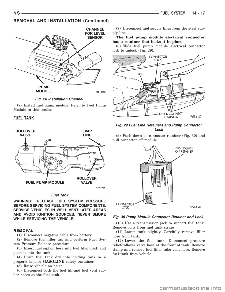
(8) Slide fuel pump module electrical connector
lock to unlock (Fig. 29).
(9) Push down on connector retainer (Fig. 30) and
pull connector off module.
(10) Use a transmission jack to support fuel tank.
Remove bolts from fuel tank straps.
(11) Lower tank slightly. Carefully remove filler
hose from tank.
(12) Lower the fuel tank. Disconnect pressure
relief/rollover valve hose at the front of tank. Remove
clamp and remove fuel filler tube vent hose. Remove
fuel tank from vehicle.
Fig. 28 Installation Channel
Fuel Tank
Fig. 29 Fuel Line Retainers and Pump Connector
Lock
Fig. 30 Pump Module Connector Retainer and Lock
NSFUEL SYSTEM 14 - 17
REMOVAL AND INSTALLATION (Continued)
Page 1393 of 1938
fuel fitting. Refer to Tube/Fitting Assembly in the
Fuel Delivery section of this Group.
(7) Attach filler line to filler tube. Pull on connec-
tor to make sure of connection.
(8) Fill fuel tank, replace cap, and connect battery
negative cable.
FUEL RESERVOIR MODULE
REMOVAL
WARNING: THE FUEL RESERVOIR OF THE FUEL
MODULE DOES NOT EMPTY OUT WHEN THE TANK
IS DRAINED. THE FUEL IN THE RESERVOIR WILL
SPILL OUT WHEN THE MODULE IS REMOVED.
(1) Disconnect negative cable from battery.
(2) Insert fuel siphon hose into fuel filler neck and
push it into the tank.
(3) Drain fuel tank dry into holding tank or a
properly labeleddieselsafety container.
(4) Raise vehicle on hoist.
(5) Use a transmission jack to support the fuel
tank. Remove bolts from fuel tank straps. Lower
tank slightly.
(6) Clean area around fuel reservoir module and
tank to keep dirt and foreign material out of tank.
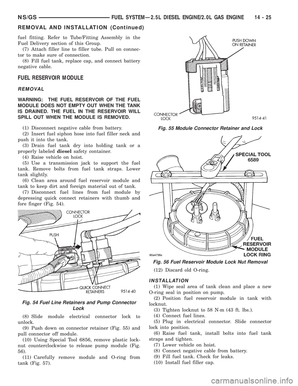
(7) Disconnect fuel lines from fuel module by
depressing quick connect retainers with thumb and
fore finger (Fig. 54).
(8) Slide module electrical connector lock to
unlock.
(9) Push down on connector retainer (Fig. 55) and
pull connector off module.
(10) Using Special Tool 6856, remove plastic lock-
nut counterclockwise to release pump module (Fig.
56).
(11) Carefully remove module and O-ring from
tank (Fig. 57).(12) Discard old O-ring.
INSTALLATION
(1) Wipe seal area of tank clean and place a new
O-ring seal in position on pump.
(2) Position fuel reservoir module in tank with
locknut.
(3) Tighten locknut to 58 N´m (43 ft. lbs.).
(4) Connect fuel lines.
(5) Plug in electrical connector. Slide connector
lock into position.
(6) Raise fuel tank, install bolts into fuel tank
straps and tighten.
(7) Lower vehicle on hoist.
(8) Connect negative cable from battery.
(9) Fill fuel tank. Check for leaks.
(10) Install fuel filler cap.
Fig. 54 Fuel Line Retainers and Pump Connector
Lock
Fig. 55 Module Connector Retainer and Lock
Fig. 56 Fuel Reservoir Module Lock Nut Removal
NS/GSFUEL SYSTEMÐ2.5L DIESEL ENGINE/2.0L GAS ENGINE 14 - 25
REMOVAL AND INSTALLATION (Continued)
Page 1436 of 1938
POWER STEERING PUMP FLOW AND
PRESSURE TEST PROCEDURE
(1) Check power steering pump drive belt tension
and adjust as necessary.
(2) Disconnect power steering fluid pressure hose,
at power steering pump. Use a container for dripping
fluid.
(3) Connect Pressure Gauge, Special Tool from kit
6815 to both hoses using adapter fittings. Connect
spare pressure hose, to power steering pump pres-
sure hose fitting.
(4) Completely open valve on Special Tool 6815.
(5) Start engine and let idle long enough to circu-
late power steering fluid through flow/pressure test
and get air out of fluid. Then shut off engine.
(6) Check power steering fluid level, and add fluid
as necessary. Start engine again and let idle.
(7) Pressure gauge should read below 862 kPa
(125 psi), if above, inspect the hoses for restrictions
and repair as necessary. The initial pressure reading
should be in the range of 345-552 kPa (50-80 psi).
The flow meter should read between 1.3 and 1.9
GPM
CAUTION: The following test procedure involves
testing power steering pump maximum pressure
output and flow control valve operation. Do not
leave valve closed for more than 5 seconds as the
pump could be damaged.
(8) Close valve fully three times and record high-
est pressure indicated each time.All three read-
ings must be within specifications and within
345 kPa (50 psi) of each other.
NOTE: Power steering pump maximum relief pres-
sure is 9653 to 10342 kPa (1400 to 1500 psi.).
²If power steering pump pressures are within the
specifications but not within 345 kPa (50 psi) of each
other, then replace power steering pump.
²If pressures are within 345 kPa (50 psi) of each
other but below specifications, then replace power
steering pump.
CAUTION: Do not force the pump to operate
against the stops for more than 5 seconds at a time
because, pump damage will result.
(9) Open test valve. Turn steering wheel to the
extreme left and right positions until against the
stops, recording the highest indicated pressure at
each position. Compare pressure gauge readings to
power steering pump specifications. If highest output
pressures are not the same against either stop, the
steering gear is leaking internally and must be
replaced.
SERVICE PROCEDURES
POWER STEERING SYSTEM FLUID LEVEL CHECK
WARNING: FLUID LEVEL SHOULD BE CHECKED
WITH ENGINE OFF TO PREVENT INJURY FROM
MOVING PARTS. DO NOT USE AUTOMATIC TRANS-
MISSION FLUID IN THE POWER STEERING SYS-
TEM. DO NOT OVERFILL THE POWER STEERING
SYSTEM.
Wipe reservoir filler cap free of dirt. Then check
fluid level. The dipstick should indicate COLD when
fluid is at normal ambient temperature, approxi-
mately 21ÉC to 27ÉC (70ÉF to 80ÉF). In all pumps add
fluid as necessary, use onlyMopar Power Steering
Fluid, or equivalent. DO NOT USE ANY TYPE
OF AUTOMATIC TRANSMISSION FLUID.
POWER STEERING PUMP INITIAL OPERATION
CAUTION: The fluid level should be checked with
engine off to prevent injury from moving compo-
nents. Use only MoparTPower Steering Fluid. Do
not use automatic transmission fluid. Do not over-
fill.
Wipe filler cap clean, then check the fluid level.
The dipstick should indicateFULL COLDwhen the
fluid is at normal temperature of approximately 21ÉC
to 27ÉC (70ÉF to 80ÉF).
(1) Fill the pump fluid reservoir to the proper level
and let the fluid settle for at least two (2) minutes.
(2) Start the engine and let run for a few seconds.
Then turn the engine off.
(3) Add fluid if necessary. Repeat the above proce-
dure until the fluid level remains constant after run-
ning the engine.
(4) Raise the front wheels off the ground.
(5) Start the engine. Slowly turn the steering
wheel right and left, lightly contacting the wheel
stops.
(6) Add power steering fluid if necessary.
(7) Lower the vehicle and turn the steering wheel
slowly from lock to lock.
(8) Stop the engine. Check the fluid level and refill
as required.
(9) If the fluid is extremely foamy, allow the vehi-
cle to stand a few minutes and repeat the above pro-
cedure.
19 - 10 STEERINGNS
DIAGNOSIS AND TESTING (Continued)
Page 1445 of 1938
cation and Maintenance section of this service man-
ual, for the required lifting procedure to be used for
this vehicle.
(5) Remove at power steering pump, the power
steering fluid hose coming from the power steering
fluid reservoir. Let the power steering fluid drain out
of the reservoir and hose.
(6) Lower vehicle.
(7) Remove hose clamp attaching the power steer-
ing fluid supply hose to the power steering fluid res-
ervoir (Fig. 24).
(8) Remove the power steering fluid supply hose
from the vehicle. Hose is removed from the top of the
engine compartment.
INSTALL
CAUTION: On V-6 engine applications, the power
steering fluid reservoir to power steering hose must
be routed tightly against the strut tower and parallel
to the dash panel. It must also be routed under the
wiring harness and below the drip tube. This rout-
ing will prevent the power steering fluid supply
hose from coming in contact with the accessory
drive belt.
(1) Install and correctly route the power steering
fluid supply hose from remote fluid reservoir down to
power steering pump.
(2) Install the fluid supply hose onto the power
steering fluid reservoir (Fig. 24). Install the hose
clamp on the fluid supply hose.Be sure hose clamp
is installed past bead on fluid reservoir fitting.
(3) Raise vehicle on jack stands or centered on a
frame contact type hoist. See Hoisting in the Lubri-
cation and Maintenance section of this service man-
ual, for the required lifting procedure to be used for
this vehicle.
(4) Install power steering fluid supply hose on
power steering pump. Install the hose clamp on the
fluid supply hose.Be sure hose clamp is installed
past bead on pump fitting.
(5) Lower vehicle.
(6) Install routing clip on power steering fluid sup-
ply hose. Be sure routing clip is installed in a posi-
tion to correctly align with stud in strut tower.
(7) Install routing clip for power steering fluid sup-
ply hose on stud in strut tower (Fig. 25).
(8) Fill the remote fluid reservoir to the proper
level and let the fluid settle for at least two (2) min-
utes.
(9) Start the engine and let run for a few seconds.
Then turn the engine off.
(10) Add fluid if necessary. Repeat the above pro-
cedure until the fluid level remains constant after
running the engine.
(11) Raise the front wheels off the ground.(12) Start the engine. Slowly turn the steering
wheel right and left, lightly contacting the wheel
stops.
(13) Add power steering fluid if necessary.
(14) Lower the vehicle and turn the steering wheel
slowly from lock to lock.
(15) Stop the engine. Check the fluid level and
refill as required.
(16) If the fluid is extremely foamy, allow the vehi-
cle to stand a few minutes and repeat the above pro-
cedure.
POWER STEERING FLUID PRESSURE HOSE
Service all power steering hoses with vehicle raised
on hoist. Cap all open ends of hoses, power steering
pump fittings and steering gear ports to prevent
entry of foreign material into the components.
WARNING: POWER STEERING OIL, ENGINE
PARTS AND THE EXHAUST SYSTEM MAY BE
EXTREMELY HOT IF ENGINE HAS BEEN RUNNING.
DO NOT START ENGINE WITH ANY LOOSE OR DIS-
CONNECTED HOSES. DO NOT ALLOW HOSES TO
TOUCH HOT EXHAUST MANIFOLD OR CATALYST.
For part reference and part location for the vehicle
that is being serviced, refer to the following figure
numbers. These show the hose bracket locations,
hose routings and fitting locations by the engine
application of the vehicle. Use these figure numbers
when referring to the removal or installation proce-
dures for the power steering hoses listed below.
REMOVE
(1) Remove cap from power steering fluid reser-
voir.
(2) Using a siphon pump, remove as much power
steering fluid as possible from the power steering
fluid reservoir.
(3) Raise vehicle See Hoisting, Group 0. Put oil
drain pan under vehicle to catch power steering fluid.
(4) Raise the heat sleeve on the power steering
fluid return hose (Fig. 26) to expose the return hose
to steel tube connection. Remove the hose clamp from
the power steering fluid return hose (Fig. 26).
Remove power steering fluid return hose from steel
tube and allow power steering fluid to drain from
pump.
NSSTEERING 19 - 19
REMOVAL AND INSTALLATION (Continued)
Page 1492 of 1938
(13) Remove the pan and clean all sealant from
the pan and transaxle mating surfaces. Clean the
magnet and the inside of the pan.
(14) Separate the filter from the valve body to
allow additional fluid to drain from the transaxle.
Inspect the filter O-ring for any damage and replace
as necessary.
(15) After the transaxle has stopped draining,
reinstall the filter and O-ring.
(16) Apply a 1/8 inch bead of Mopar RTV Sealant
to the mounting flange of the transaxle oil pan.
Apply RTV Sealant to the underside of the attaching
bolts. Attach the oil pan to the transaxle. Tighten the
bolts to 19 N²m (165 in. lbs.).
(17) Lower the vehicle and add 4 Quarts of Mopar
ATF Plus 3 Type 7176 transaxle fluid.
(18) Start the engine and allow it to idle for a min-
imum of one minute. With the parking brake applied,
press your foot on the service brake and cycle the
transaxle from park to all gear positions ending in
neutral or park.
(19) Check the transaxle fluid level and add an
appropriate amount to bring the transaxle fluid level
to 3mm (1/8 in.) below the ADD mark on the dip-
stick.
(20) Recheck the fluid level after the transaxle is
at normal operating temperature. The level should be
in the HOT range.
FLUID DRAIN AND REFILL
(1) Raise vehicle on a hoist (See Group 0, Lubrica-
tion). Place a drain container with a large opening,
under transaxle oil pan.
(2) Loosen pan bolts and tap the pan at one corner
to break it loose allowing fluid to drain, then remove
the oil pan.
(3) Install a new filter and gasket on bottom of the
valve body and tighten retaining screws to 5 N´m (40
inch-pounds).
(4) Clean the oil pan and magnet. Reinstall pan
using new sealant. Tighten oil pan bolts to 19 N´m
(165 in. lbs.).
(5) Pour four quarts of Mopar ATF PLUS 3 (Auto-
matic Transmission Fluid) Type 7176 through the
dipstick opening.
(6) Start engine and allow to idle for at least one
minute. Then, with parking and service brakes
applied, move selector lever momentarily to each
position, ending in the park or neutral position.
(7) Add sufficient fluid to bring level to 1/8 inch
below the ADD mark.
(8) Recheck fluid level after transaxle is at normal
operating temperature. The level should be in the
HOT region.
ALUMINUM THREAD REPAIR
Damaged or worn threads in the aluminum transaxle
case and valve body can be repaired by the use of Heli-
Coils, or equivalent. This repair consists of drilling out
the worn-out damaged threads. Then tapping the hole
with a Heli-Coil tap, or equivalent, and installing a
Heli-Coil insert, or equivalent, into the hole. This
brings the hole back to its original thread size.
Heli-Coil, or equivalent, tools and inserts are readily
available from most automotive parts suppliers.
FLUSHING COOLERS AND TUBES
When a transaxle failure has contaminated the
fluid, the oil cooler(s) must be flushed. The cooler
bypass valve in the transaxle must be replaced also.
The torque converter must also be replaced with an
exchange unit. This will ensure that metal particles
or sludged oil are not later transferred back into the
reconditioned (or replaced) transaxle.
The recommended procedure for flushing the cool-
ers and tubes is to use Tool 6906A Cooler Flusher.
WARNING: WEAR PROTECTIVE EYEWEAR THAT
MEETS THE REQUIREMENTS OF OSHA AND ANSI
Z87.1±1968. WEAR STANDARD INDUSTRIAL RUB-
BER GLOVES.
KEEP LIGHTED CIGARETTES, SPARKS, FLAMES,
AND OTHER IGNITION SOURCES AWAY FROM THE
AREA TO PREVENT THE IGNITION OF COMBUSTI-
BLE LIQUIDS AND GASES. KEEP A CLASS (B) FIRE
EXTINGUISHER IN THE AREA WHERE THE
FLUSHER WILL BE USED.
KEEP THE AREA WELL VENTILATED.
DO NOT LET FLUSHING SOLVENT COME IN CON-
TACT WITH YOUR EYES OR SKIN: IF EYE CONTAM-
INATION OCCURS, FLUSH EYES WITH WATER FOR
15 TO 20 SECONDS. REMOVE CONTAMINATED
CLOTHING AND WASH AFFECTED SKIN WITH
SOAP AND WATER. SEEK MEDICAL ATTENTION.
COOLER FLUSH USING TOOL 6906A
(1) Remove cover plate filler plug on Tool 6906A.
Fill reservoir 1/2 to 3/4 full of fresh flushing solution.
Flushing solvents are petroleum based solutions gen-
erally used to clean automatic transmission compo-
nents.DO NOTuse solvents containing acids, water,
gasoline, or any other corrosive liquids.
(2) Reinstall filler plug on Tool 6906A.
(3) Verify pump power switch is turned OFF. Con-
nect red alligator clip to positive (+) battery post.
Connect black (-) alligator clip to a good ground.
(4) Disconnect the cooler lines at the transmission.
NOTE: When flushing transmission cooler and
lines, ALWAYS reverse flush.
21 - 18 TRANSAXLE AND POWER TRANSFER UNITNS
SERVICE PROCEDURES (Continued)
Page 1556 of 1938
WARNING: WEAR PROTECTIVE EYEWEAR THAT
MEETS THE REQUIREMENTS OF OSHA AND ANSI
Z87.1±1968. WEAR STANDARD INDUSTRIAL RUB-
BER GLOVES.
KEEP LIGHTED CIGARETTES, SPARKS, FLAMES,
AND OTHER IGNITION SOURCES AWAY FROM THE
AREA TO PREVENT THE IGNITION OF COMBUSTI-
BLE LIQUIDS AND GASES. KEEP A CLASS (B) FIRE
EXTINGUISHER IN THE AREA WHERE THE
FLUSHER WILL BE USED.
KEEP THE AREA WELL VENTILATED.
DO NOT LET FLUSHING SOLVENT COME IN CON-
TACT WITH YOUR EYES OR SKIN: IF EYE CONTAM-
INATION OCCURS, FLUSH EYES WITH WATER FOR
15 TO 20 SECONDS. REMOVE CONTAMINATED
CLOTHING AND WASH AFFECTED SKIN WITH
SOAP AND WATER. SEEK MEDICAL ATTENTION.
COOLER FLUSH USING TOOL 6906A
(1) Remove cover plate filler plug on Tool 6906A.
Fill reservoir 1/2 to 3/4 full of fresh flushing solution.
Flushing solvents are petroleum based solutions gen-
erally used to clean automatic transmission compo-
nents.DO NOTuse solvents containing acids, water,
gasoline, or any other corrosive liquids.
(2) Reinstall filler plug on Tool 6906A.
(3) Verify pump power switch is turned OFF. Con-
nect red alligator clip to positive (+) battery post.
Connect black (-) alligator clip to a good ground.
(4) Disconnect the cooler lines at the transmission.
NOTE: When flushing transmission cooler and
lines, ALWAYS reverse flush.
(5) Connect the BLUE pressure line to the OUT-
LET (From) cooler line.
(6) Connect the CLEAR return line to the INLET
(To) cooler line
(7) Turn pump ON for two to three minutes to
flush cooler(s) and lines. Monitor pressure readings
and clear return lines. Pressure readings should sta-
bilize below 20 psi. for vehicles equipped with a sin-
gle cooler and 30 psi. for vehicles equipped with dual
coolers. If flow is intermittent or exceeds these pres-
sures, replace cooler.
(8) Turn pump OFF.
(9) Disconnect CLEAR suction line from reservoir
at cover plate. Disconnect CLEAR return line at
cover plate, and place it in a drain pan.
(10) Turn pump ON for 30 seconds to purge flush-
ing solution from cooler and lines. Turn pump OFF.
(11) Place CLEAR suction line into a one quart
container of MopartATF PLUS 3 Type 7176 auto-
matic transmission fluid.
(12) Turn pump ON until all transmission fluid is
removed from the one quart container and lines. Thispurges any residual cleaning solvent from the trans-
mission cooler and lines. Turn pump OFF.
(13) Disconnect alligator clips from battery. Recon-
nect flusher lines to cover plate, and remove flushing
adapters from cooler lines.
OIL PUMP VOLUME CHECK
After the new or repaired transmission has been
installed, fill to the proper level with Mopar ATF
PLUS 3 (Type 7176) automatic transmission fluid.
The volume should be checked using the following
procedure:
(1) Disconnect theFrom coolerline at the trans-
mission and place a collecting container under the
disconnected line.
CAUTION: With the fluid set at the proper level,
fluid collection should not exceed (1) quart or inter-
nal damage to the transmission may occur.
(2) Run the engineat curb idle speed, with the
shift selector in neutral.
(3) If fluid flow is intermittent or it takes more
than 20 seconds to collect one quart of ATF, discon-
nect theTo Coolerline at the transaxle.
(4) Refill the transaxle to proper level and recheck
pump volume.
(5) If flow is found to be within acceptable limits,
replace the cooler. Then fill transmission to the
proper level, using Mopar ATF PLUS 3 (Type 7176)
automatic transmission fluid.
(6) If fluid flow is still found to be inadequate,
check the line pressure using the Transaxle Hydrau-
lic Pressure Test procedure.
(7) Check the cooler for debris on the external sur-
faces. Clean as necessary.
TRANSAXLE QUICK LEARN PROCEDURE
The quick learn procedure requires the use of the
DRBIII scan tool.
This program allows the electronic transaxle sys-
tem to recalibrate itself. This will provide the best
possible transaxle operation. The quick learn proce-
dure should be performed if any of the following pro-
cedures are performed:
²Transaxle Assembly Replacement
²Transmission Control Module Replacement
²Solenoid Pack Replacement
²Clutch Plate and/or Seal Replacement
²Valve Body Replacement or Recondition
To perform the Quick Learn Procedure, the follow-
ing conditions must be met:
²The brakes must be applied
²The engine speed must be above 500 rpm
²The throttle angle (TPS) must be less than 3
degrees
21 - 82 TRANSAXLE AND POWER TRANSFER UNITNS
SERVICE PROCEDURES (Continued)
Page 1753 of 1938
SHOULDER BELT HEIGHT ADJUSTER KNOB . . 64
SHOULDER BELT HEIGHT ADJUSTER±BOR
C-PILLAR............................ 64
SIDE VIEW MIRROR..................... 64
SLIDING DOOR CENTER HINGE............ 66
SLIDING DOOR CENTER STOP TRIM COVER . . 66
SLIDING DOOR CENTER STRIKER ASSEMBLY . 67
SLIDING DOOR HOLD OPEN LATCH STRIKER . 67
SLIDING DOOR HOLD OPEN LATCH......... 67
SLIDING DOOR INSIDE LATCH HANDLE
BELLCRANK.......................... 68
SLIDING DOOR INSIDE LATCH HANDLE...... 68
SLIDING DOOR INSIDE LATCH RELEASE
MECHANISM.......................... 69
SLIDING DOOR LATCH STRIKER........... 69
SLIDING DOOR LATCH/LOCK CONTROL..... 70
SLIDING DOOR LOWER ROLLER ARM
BRACKET............................ 71
SLIDING DOOR LOWER ROLLER ARM....... 71SLIDING DOOR OUTSIDE LATCH RELEASE
HANDLE............................. 72
SLIDING DOOR REAR LATCH.............. 73
SLIDING DOOR SILL PLATE............... 73
SLIDING DOOR STABILIZER SOCKET........ 74
SLIDING DOOR STABILIZER............... 73
SLIDING DOOR STOP BUMPER............ 74
SLIDING DOOR TRIM PANEL............... 74
SLIDING DOOR UPPER ROLLER............ 75
SLIDING DOOR WEATHER-STRIP........... 75
SLIDING DOOR......................... 64
STICK-ON BODY SIDE MOLDING........... 75
SUN VISOR SUPPORT................... 78
SUN VISOR............................ 76
UPPER B-PILLAR TRIM COVER............. 78
UPPER C-PILLAR TRIM................... 80
ADJUSTMENTS
SLIDING DOOR ADJUSTMENTS............ 80
DIAGNOSIS AND TESTING
WATER LEAKS
Water leaks can be caused by poor sealing,
improper body component alignment, body seam
porosity, missing plugs, or blocked drain holes. Cen-
trifugal and gravitational force can cause water to
drip from a location away from the actual leak point,
making leak detection difficult. All body sealing
points should be water tight in normal wet-driving
conditions. Water flowing downward from the front of
the vehicle should not enter the passenger or luggage
compartment. Moving sealing surfaces will not
always seal water tight under all conditions. At
times, side glass or door seals will allow water to
enter the passenger compartment during high pres-
sure washing or hard driving rain (severe) condi-
tions. Overcompensating on door or glass
adjustments to stop a water leak that occurs under
severe conditions can cause premature seal wear and
excessive closing or latching effort. After completing
a repair, water-test vehicle to verify leak has stopped
before returning vehicle to use.
VISUAL INSPECTION BEFORE WATER LEAK
TESTS
Verify that floor and body plugs are in place, body
drains are clear, and body components are properly
aligned and sealed. If component alignment or seal-
ing is necessary, refer to the appropriate section of
this group for proper procedures.
WATER LEAK TESTS
WARNING: DO NOT USE ELECTRIC SHOP LIGHTS
OR TOOLS IN WATER TEST AREA. PERSONAL
INJURY CAN RESULT.When the conditions causing a water leak have
been determined, simulate the conditions as closely
as possible.
²If a leak occurs with the vehicle parked in a
steady light rain, flood the leak area with an open-
ended garden hose.
²If a leak occurs while driving at highway speeds
in a steady rain, test the leak area with a reasonable
velocity stream or fan spray of water. Direct the
spray in a direction comparable to actual conditions.
²If a leak occurs when the vehicle is parked on an
incline, hoist the end or side of the vehicle to simu-
late this condition. This method can be used when
the leak occurs when the vehicle accelerates, stops or
turns. If the leak occurs on acceleration, hoist the
front of the vehicle. If the leak occurs when braking,
hoist the back of the vehicle. If the leak occurs on left
turns, hoist the left side of the vehicle. If the leak
occurs on right turns, hoist the right side of the vehi-
cle. For hoisting recommendations refer to Group 0,
Lubrication and Maintenance, General Information
section.
WATER LEAK DETECTION
To detect a water leak point-of-entry, do a water
test and watch for water tracks or droplets forming
on the inside of the vehicle. If necessary, remove inte-
rior trim covers or panels to gain visual access to the
leak area. If the hose cannot be positioned without
being held, have someone help do the water test.
NSBODY 23 - 23
Page 1831 of 1938
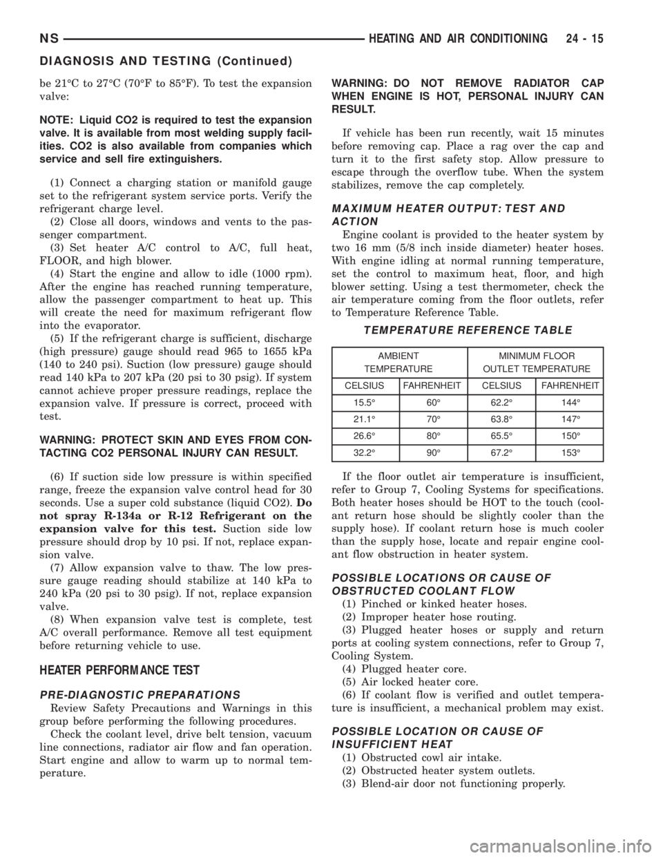
be 21ÉC to 27ÉC (70ÉF to 85ÉF). To test the expansion
valve:
NOTE: Liquid CO2 is required to test the expansion
valve. It is available from most welding supply facil-
ities. CO2 is also available from companies which
service and sell fire extinguishers.
(1) Connect a charging station or manifold gauge
set to the refrigerant system service ports. Verify the
refrigerant charge level.
(2) Close all doors, windows and vents to the pas-
senger compartment.
(3) Set heater A/C control to A/C, full heat,
FLOOR, and high blower.
(4) Start the engine and allow to idle (1000 rpm).
After the engine has reached running temperature,
allow the passenger compartment to heat up. This
will create the need for maximum refrigerant flow
into the evaporator.
(5) If the refrigerant charge is sufficient, discharge
(high pressure) gauge should read 965 to 1655 kPa
(140 to 240 psi). Suction (low pressure) gauge should
read 140 kPa to 207 kPa (20 psi to 30 psig). If system
cannot achieve proper pressure readings, replace the
expansion valve. If pressure is correct, proceed with
test.
WARNING: PROTECT SKIN AND EYES FROM CON-
TACTING CO2 PERSONAL INJURY CAN RESULT.
(6) If suction side low pressure is within specified
range, freeze the expansion valve control head for 30
seconds. Use a super cold substance (liquid CO2).Do
not spray R-134a or R-12 Refrigerant on the
expansion valve for this test.Suction side low
pressure should drop by 10 psi. If not, replace expan-
sion valve.
(7) Allow expansion valve to thaw. The low pres-
sure gauge reading should stabilize at 140 kPa to
240 kPa (20 psi to 30 psig). If not, replace expansion
valve.
(8) When expansion valve test is complete, test
A/C overall performance. Remove all test equipment
before returning vehicle to use.
HEATER PERFORMANCE TEST
PRE-DIAGNOSTIC PREPARATIONS
Review Safety Precautions and Warnings in this
group before performing the following procedures.
Check the coolant level, drive belt tension, vacuum
line connections, radiator air flow and fan operation.
Start engine and allow to warm up to normal tem-
perature.WARNING: DO NOT REMOVE RADIATOR CAP
WHEN ENGINE IS HOT, PERSONAL INJURY CAN
RESULT.
If vehicle has been run recently, wait 15 minutes
before removing cap. Place a rag over the cap and
turn it to the first safety stop. Allow pressure to
escape through the overflow tube. When the system
stabilizes, remove the cap completely.
MAXIMUM HEATER OUTPUT: TEST AND
ACTION
Engine coolant is provided to the heater system by
two 16 mm (5/8 inch inside diameter) heater hoses.
With engine idling at normal running temperature,
set the control to maximum heat, floor, and high
blower setting. Using a test thermometer, check the
air temperature coming from the floor outlets, refer
to Temperature Reference Table.
If the floor outlet air temperature is insufficient,
refer to Group 7, Cooling Systems for specifications.
Both heater hoses should be HOT to the touch (cool-
ant return hose should be slightly cooler than the
supply hose). If coolant return hose is much cooler
than the supply hose, locate and repair engine cool-
ant flow obstruction in heater system.
POSSIBLE LOCATIONS OR CAUSE OF
OBSTRUCTED COOLANT FLOW
(1) Pinched or kinked heater hoses.
(2) Improper heater hose routing.
(3) Plugged heater hoses or supply and return
ports at cooling system connections, refer to Group 7,
Cooling System.
(4) Plugged heater core.
(5) Air locked heater core.
(6) If coolant flow is verified and outlet tempera-
ture is insufficient, a mechanical problem may exist.
POSSIBLE LOCATION OR CAUSE OF
INSUFFICIENT HEAT
(1) Obstructed cowl air intake.
(2) Obstructed heater system outlets.
(3) Blend-air door not functioning properly.
TEMPERATURE REFERENCE TABLE
AMBIENT
TEMPERATUREMINIMUM FLOOR
OUTLET TEMPERATURE
CELSIUS FAHRENHEIT CELSIUS FAHRENHEIT
15.5É 60É 62.2É 144É
21.1É 70É 63.8É 147É
26.6É 80É 65.5É 150É
32.2É 90É 67.2É 153É
NSHEATING AND AIR CONDITIONING 24 - 15
DIAGNOSIS AND TESTING (Continued)
Page 1865 of 1938
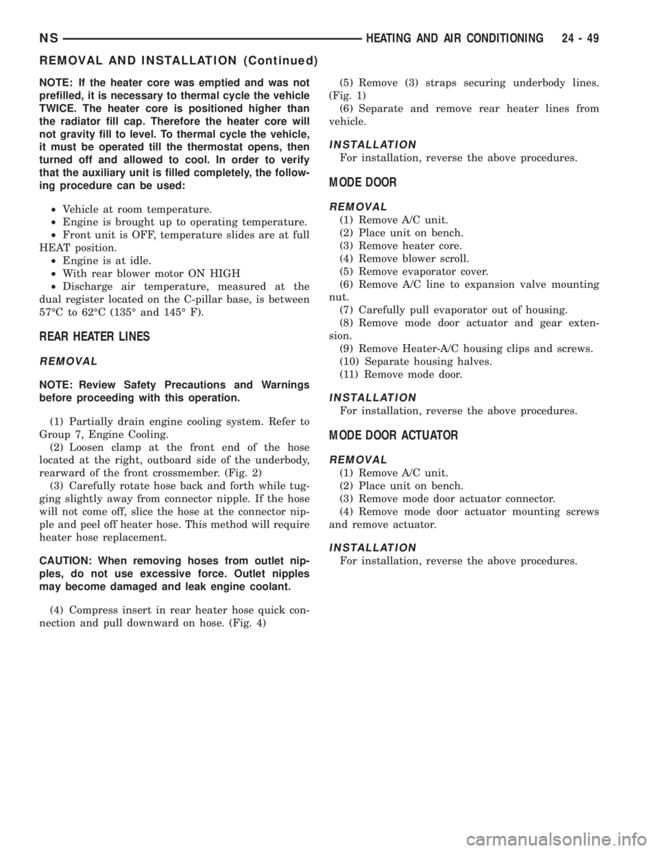
NOTE: If the heater core was emptied and was not
prefilled, it is necessary to thermal cycle the vehicle
TWICE. The heater core is positioned higher than
the radiator fill cap. Therefore the heater core will
not gravity fill to level. To thermal cycle the vehicle,
it must be operated till the thermostat opens, then
turned off and allowed to cool. In order to verify
that the auxiliary unit is filled completely, the follow-
ing procedure can be used:
²Vehicle at room temperature.
²Engine is brought up to operating temperature.
²Front unit is OFF, temperature slides are at full
HEAT position.
²Engine is at idle.
²With rear blower motor ON HIGH
²Discharge air temperature, measured at the
dual register located on the C-pillar base, is between
57ÉC to 62ÉC (135É and 145É F).
REAR HEATER LINES
REMOVAL
NOTE: Review Safety Precautions and Warnings
before proceeding with this operation.
(1) Partially drain engine cooling system. Refer to
Group 7, Engine Cooling.
(2) Loosen clamp at the front end of the hose
located at the right, outboard side of the underbody,
rearward of the front crossmember. (Fig. 2)
(3) Carefully rotate hose back and forth while tug-
ging slightly away from connector nipple. If the hose
will not come off, slice the hose at the connector nip-
ple and peel off heater hose. This method will require
heater hose replacement.
CAUTION: When removing hoses from outlet nip-
ples, do not use excessive force. Outlet nipples
may become damaged and leak engine coolant.
(4) Compress insert in rear heater hose quick con-
nection and pull downward on hose. (Fig. 4)(5) Remove (3) straps securing underbody lines.
(Fig. 1)
(6) Separate and remove rear heater lines from
vehicle.
INSTALLATION
For installation, reverse the above procedures.
MODE DOOR
REMOVAL
(1) Remove A/C unit.
(2) Place unit on bench.
(3) Remove heater core.
(4) Remove blower scroll.
(5) Remove evaporator cover.
(6) Remove A/C line to expansion valve mounting
nut.
(7) Carefully pull evaporator out of housing.
(8) Remove mode door actuator and gear exten-
sion.
(9) Remove Heater-A/C housing clips and screws.
(10) Separate housing halves.
(11) Remove mode door.
INSTALLATION
For installation, reverse the above procedures.
MODE DOOR ACTUATOR
REMOVAL
(1) Remove A/C unit.
(2) Place unit on bench.
(3) Remove mode door actuator connector.
(4) Remove mode door actuator mounting screws
and remove actuator.
INSTALLATION
For installation, reverse the above procedures.
NSHEATING AND AIR CONDITIONING 24 - 49
REMOVAL AND INSTALLATION (Continued)