diagram CHRYSLER VOYAGER 1996 Repair Manual
[x] Cancel search | Manufacturer: CHRYSLER, Model Year: 1996, Model line: VOYAGER, Model: CHRYSLER VOYAGER 1996Pages: 1938, PDF Size: 55.84 MB
Page 1355 of 1938
PCM. If OK, replace MAP sensor. If not OK, repair or
replace the wire harness as required.
HEATED OXYGEN SENSOR
Use an ohmmeter to test the heating element of
the oxygen sensors. Disconnect the electrical connec-
tor from each oxygen sensor. The white wires in the
sensor connector are the power and ground circuits
for the heater. Connect the ohmmeter test leads to
terminals of the white wires in the heated oxygen
sensor connector. Replace the heated oxygen sensor if
the resistance is not between 4 and 7 ohms.
KNOCK SENSOR
The engine knock sensor is affected by a number of
factors. A few of these are: ignition timing, cylinder
pressure, fuel octane, etc. The knock sensor gener-
ates an AC voltage whose amplitude increases with
the increase of engine knock. The knock sensor can
be tested with a digital voltmeter. The RMS voltage
starts at about 20mVac (at about 700 rpm) and
increases to approximately 600 mVac (5000 rpm). If
the output falls outside of this range a DTC will be
set.
CAMSHAFT AND CRANKSHAFT POSITION SENSOR
Refer to Group 8D, Ignition for Diagnosis and Test-
ing of Camshaft and Crankshaft Sensors.
ENGINE COOLANT TEMPERATURE SENSOR
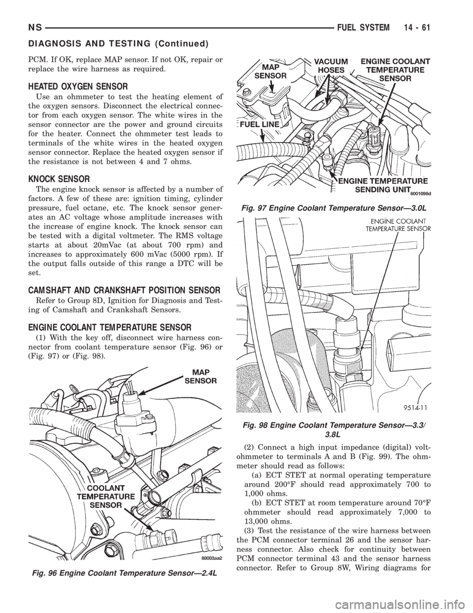
(1) With the key off, disconnect wire harness con-
nector from coolant temperature sensor (Fig. 96) or
(Fig. 97) or (Fig. 98).
(2) Connect a high input impedance (digital) volt-
ohmmeter to terminals A and B (Fig. 99). The ohm-
meter should read as follows:
(a) ECT STET at normal operating temperature
around 200ÉF should read approximately 700 to
1,000 ohms.
(b) ECT STET at room temperature around 70ÉF
ohmmeter should read approximately 7,000 to
13,000 ohms.
(3) Test the resistance of the wire harness between
the PCM connector terminal 26 and the sensor har-
ness connector. Also check for continuity between
PCM connector terminal 43 and the sensor harness
connector. Refer to Group 8W, Wiring diagrams for
Fig. 96 Engine Coolant Temperature SensorÐ2.4L
Fig. 97 Engine Coolant Temperature SensorÐ3.0L
Fig. 98 Engine Coolant Temperature SensorÐ3.3/
3.8L
NSFUEL SYSTEM 14 - 61
DIAGNOSIS AND TESTING (Continued)
Page 1421 of 1938

²When the PCM energizes the Diesel PCM and
other relays, terminal 87 connects to terminal 30.
This is the On position. Terminal 87 supplies voltage
to the rest of the circuit.
TESTING
The following procedure applies to the Diesel PCM
and other relays.
(1) Remove relay from connector before testing.
(2) With the relay removed from the vehicle, use
an ohmmeter to check the resistance between termi-
nals 85 and 86. The resistance should be between 75
65 ohms.
(3) Connect the ohmmeter between terminals 30
and 87A. The ohmmeter should show continuity
between terminals 30 and 87A.
(4) Connect the ohmmeter between terminals 87
and 30. The ohmmeter should not show continuity at
this time.
(5) Connect one end of a jumper wire (16 gauge or
smaller) to relay terminal 85. Connect the other end
of the jumper wire to the ground side of a 12 volt
power source.
(6) Connect one end of another jumper wire (16
gauge or smaller) to the power side of the 12 volt
power source.Do not attach the other end of the
jumper wire to the relay at this time.
WARNING: DO NOT ALLOW OHMMETER TO CON-
TACT TERMINALS 85 OR 86 DURING THIS TEST.
(7) Attach the other end of the jumper wire to
relay terminal 86. This activates the relay. The ohm-meter should now show continuity between relay ter-
minals 87 and 30. The ohmmeter should not show
continuity between relay terminals 87A and 30.
(8) Disconnect jumper wires.
(9) Replace the relay if it did not pass the continu-
ity and resistance tests. If the relay passed the tests,
it operates properly. Check the remainder of the Die-
sel PCM and other relay circuits. Refer to group 8W,
Wiring Diagrams.
BOOST PRESSURE SENSOR
If the boost pressure sensor fails, the PCM records
a DTC into memory and continues to operate the
engine in one of the three ªlimp-inº modes. When the
PCM is operating in this mode, a loss of power will
be present, as if the turbocharger was not operating.
The best method for diagnosing faults with the boost
pressure sensor is with the DRB III scan tool.
Diagnostic Trouble Codes:Refer to On-Board
Diagnostics in Group 25, Emission Control System
for a list of Diagnostic Trouble Codes (DTC's) for cer-
tain fuel system components.
VEHICLE SPEED SENSOR TEST
To perform a test of the sensor and its related cir-
cuitry, refer to DRB scan tool.
Diagnostic Trouble Codes:Refer to On-Board
Diagnostics in Group 25, Emission Control System
for a list of Diagnostic Trouble Codes (DTC's) for cer-
tain fuel system components.
DIAGNOSTIC TROUBLE CODES
For a list of Diagnostic Trouble Codes (DTC's),
refer to Group 25, Emission Control System for infor-
mation. See On-Board Diagnostics.
REMOVAL AND INSTALLATION
DIESEL PCM RELAY
The Diesel PCM relay is located in the PDC. For
the location of the relay within the PDC, refer to
label on PDC cover.
A/C CLUTCH RELAY
The A/C clutch relay is located in the PDC. For the
location of the relay within the PDC, refer to label on
PDC cover.
ENGINE SPEED SENSOR
The engine speed sensor is mounted to the trans-
mission bellhousing at the rear of the engine block
(Fig. 18).
REMOVAL
(1) Disconnect the harness (on the sensor) from
the main electrical harness.
Fig. 17 Diesel PCM and Other Relay Terminals
NS/GSFUEL SYSTEMÐ2.5L DIESEL ENGINE/2.0L GAS ENGINE 14 - 53
DIAGNOSIS AND TESTING (Continued)
Page 1475 of 1938
TRANSAXLE AND POWER TRANSFER UNIT
CONTENTS
page page
31TH AUTOMATIC TRANSAXLE.............. 1
41TE AUTOMATIC TRANSAXLE............. 71POWER TRANSFER UNIT................. 165
31TH AUTOMATIC TRANSAXLE
INDEX
page page
GENERAL INFORMATION
31TH TRANSAXLE........................ 2
FLUID LEVEL AND CONDITION.............. 2
SELECTION OF LUBRICANT................ 3
SPECIAL ADDITIVES...................... 3
DESCRIPTION AND OPERATION
CLUTCHES, BAND SERVOS, AND
ACCUMULATOR
...................... 3
FLOW CONTROL VALVES.................. 3
GEARSHIFT AND PARKING LOCK CONTROLS . . 4
GOVERNOR............................. 4
HYDRAULIC CONTROL SYSTEM............. 3
PRESSURE REGULATING VALVES........... 3
PRESSURE SUPPLY SYSTEM............... 3
TORQUE CONVERTER CLUTCH SOLENOID
WIRING CONNECTOR................... 4
TORQUE CONVERTER CLUTCH............. 3
DIAGNOSIS AND TESTING
CLUTCH AND SERVO AIR PRESSURE TESTS . 15
FLUID LEAKAGE-TRANSAXLE TORQUE
CONVERTER HOUSING AREA............ 15
HYDRAULIC PRESSURE TESTS............ 13
ROAD TEST............................. 4
THREE SPEED TRANSAXLE DIAGNOSIS AND
TESTS............................... 4
SERVICE PROCEDURES
ALUMINUM THREAD REPAIR.............. 18
FLUID AND FILTER CHANGE............... 16
FLUID DRAIN AND REFILL................. 18
FLUSHING COOLERS AND TUBES.......... 18
OIL PUMP VOLUME CHECK............... 19
REMOVAL AND INSTALLATION
FRONT PUMP OIL SEAL.................. 21
PARK/NEUTRAL STARTING AND BACK-UP
LAMP SWITCH........................ 19
TRANSAXLE AND TORQUE CONVERTER
REMOVAL............................ 20
VEHICLE SPEED SENSOR PINION GEAR..... 19DISASSEMBLY AND ASSEMBLY
ACCUMULATOR-RECONDITION............ 36
DIFFERENTIAL REPAIR................... 46
FRONT CLUTCH-RECONDITION............ 32
FRONT PLANETARY & ANNULUS GEAR-
RECONDITION........................ 35
KICKDOWN SERVO (CONTROLLED LOAD)-
RECONDITION........................ 37
LOW/REVERSE (REAR)
SERVO-RECONDITION.................. 36
OIL PUMP-RECONDITION................. 31
OUTPUT SHAFT REPAIR.................. 43
PARKING PAWL......................... 42
REAR CLUTCH-RECONDITION............. 33
TRANSAXLE........................... 21
TRANSFER SHAFT REPAIR................ 38
VALVE BODY RECONDITION............... 27
CLEANING AND INSPECTION
VALVE BODY........................... 50
ADJUSTMENTS
BAND ADJUSTMENT..................... 51
BEARING ADJUSTMENT PROCEDURES...... 52
DIFFERENTIAL BEARING................. 53
GEARSHIFT CABLE ADJUSTMENT.......... 51
HYDRAULIC CONTROL PRESSURE
ADJUSTMENTS....................... 52
OUTPUT SHAFT BEARING................ 52
THROTTLE PRESSURE LINKAGE
ADJUSTMENT......................... 51
TRANSFER SHAFT BEARING.............. 54
SCHEMATICS AND DIAGRAMS
31TH TRANSAXLE HYDRAULIC SCHEMATIC . . 56
SPECIFICATIONS
31TH AUTOMATIC TRANSAXLE............. 64
31TH TORQUE SPECIFICATIONS........... 65
SPECIAL TOOLS
31TH AUTOMATIC TRANSAXLE............. 66
NSTRANSAXLE AND POWER TRANSFER UNIT 21 - 1
Page 1530 of 1938
SCHEMATICS AND DIAGRAMS
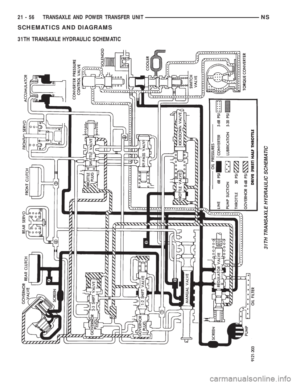
31TH TRANSAXLE HYDRAULIC SCHEMATIC
31TH TRANSAXLE HYDRAULIC SCHEMATIC
21 - 56 TRANSAXLE AND POWER TRANSFER UNITNS
Page 1531 of 1938
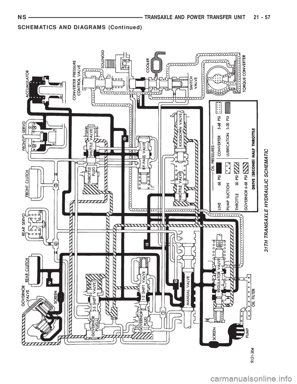
31TH TRANSAXLE HYDRAULIC SCHEMATIC
NSTRANSAXLE AND POWER TRANSFER UNIT 21 - 57
SCHEMATICS AND DIAGRAMS (Continued)
Page 1532 of 1938
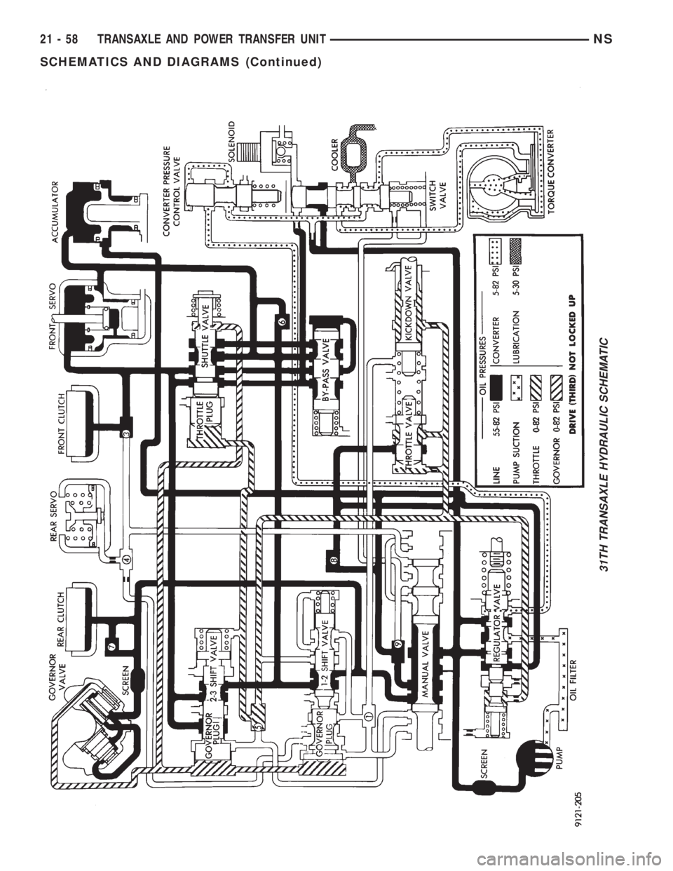
31TH TRANSAXLE HYDRAULIC SCHEMATIC
21 - 58 TRANSAXLE AND POWER TRANSFER UNITNS
SCHEMATICS AND DIAGRAMS (Continued)
Page 1533 of 1938
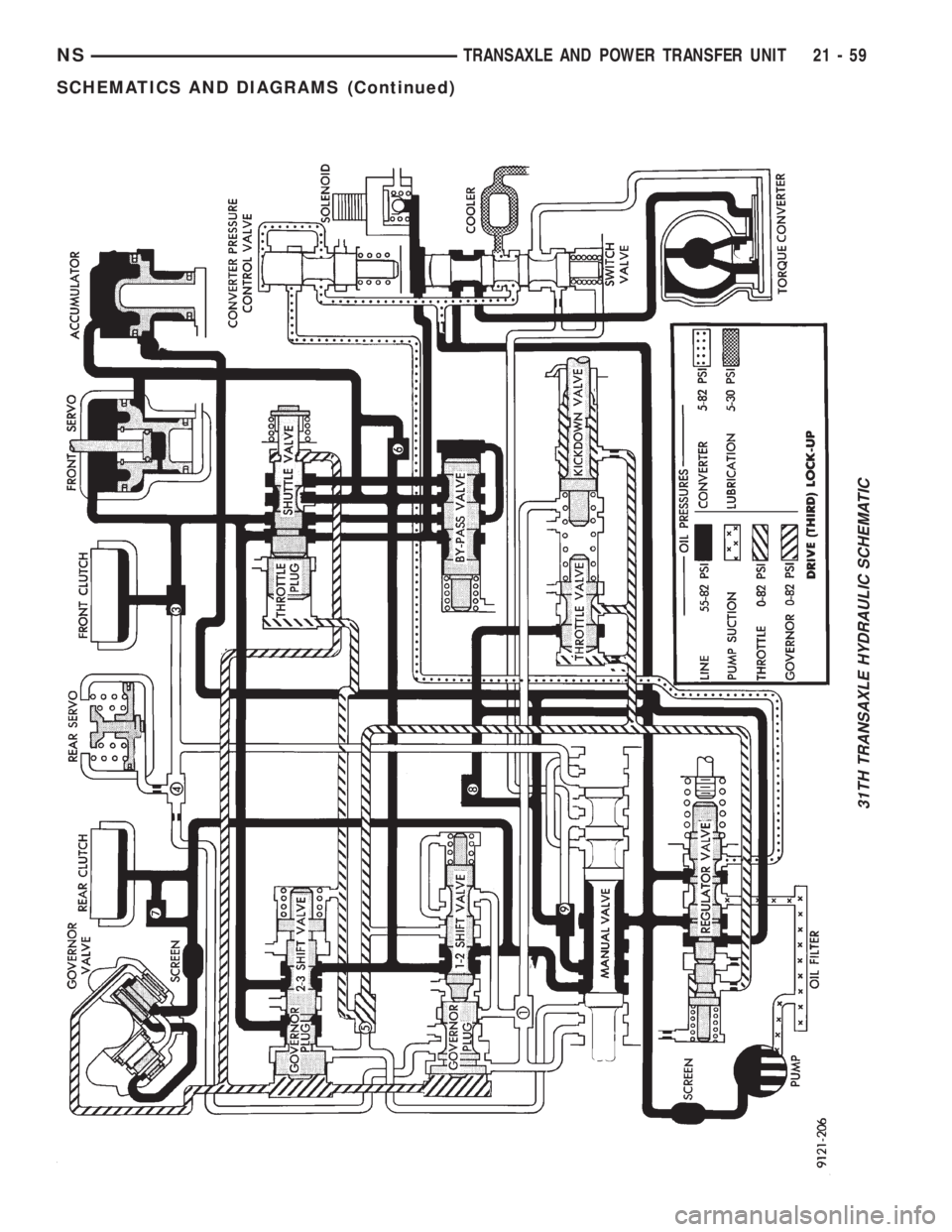
31TH TRANSAXLE HYDRAULIC SCHEMATIC
NSTRANSAXLE AND POWER TRANSFER UNIT 21 - 59
SCHEMATICS AND DIAGRAMS (Continued)
Page 1534 of 1938
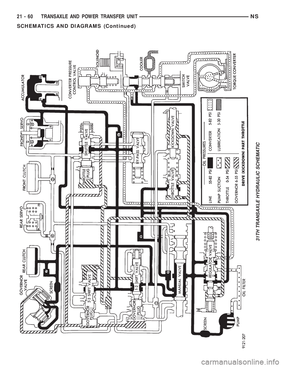
31TH TRANSAXLE HYDRAULIC SCHEMATIC
21 - 60 TRANSAXLE AND POWER TRANSFER UNITNS
SCHEMATICS AND DIAGRAMS (Continued)
Page 1535 of 1938
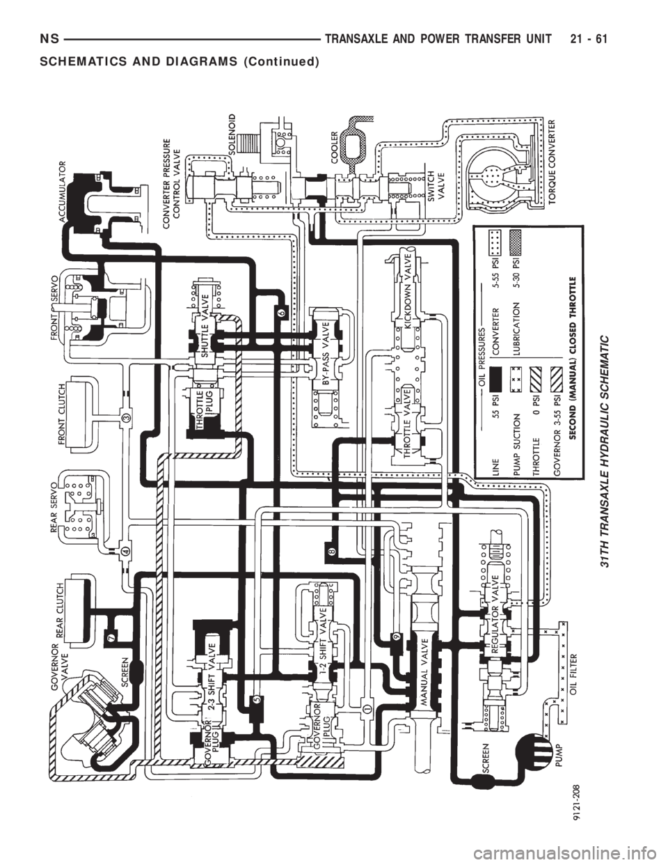
31TH TRANSAXLE HYDRAULIC SCHEMATIC
NSTRANSAXLE AND POWER TRANSFER UNIT 21 - 61
SCHEMATICS AND DIAGRAMS (Continued)
Page 1536 of 1938
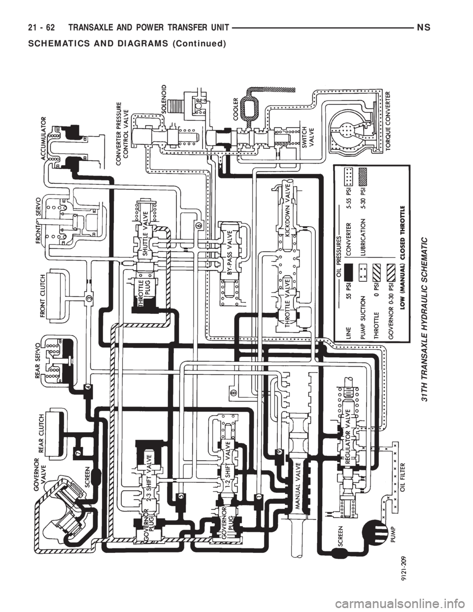
31TH TRANSAXLE HYDRAULIC SCHEMATIC
21 - 62 TRANSAXLE AND POWER TRANSFER UNITNS
SCHEMATICS AND DIAGRAMS (Continued)