torque CHRYSLER VOYAGER 1996 Workshop Manual
[x] Cancel search | Manufacturer: CHRYSLER, Model Year: 1996, Model line: VOYAGER, Model: CHRYSLER VOYAGER 1996Pages: 1938, PDF Size: 55.84 MB
Page 139 of 1938
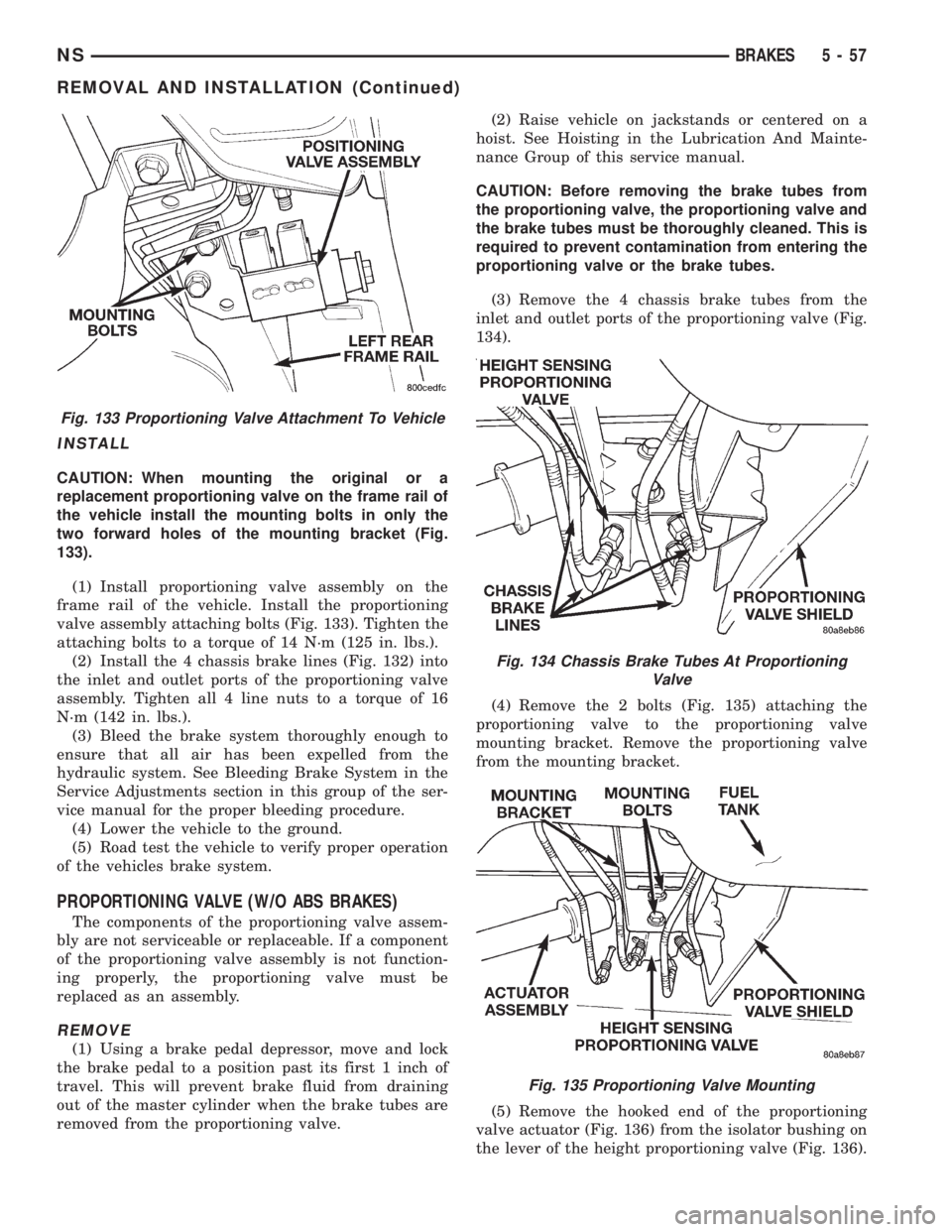
INSTALL
CAUTION: When mounting the original or a
replacement proportioning valve on the frame rail of
the vehicle install the mounting bolts in only the
two forward holes of the mounting bracket (Fig.
133).
(1) Install proportioning valve assembly on the
frame rail of the vehicle. Install the proportioning
valve assembly attaching bolts (Fig. 133). Tighten the
attaching bolts to a torque of 14 N´m (125 in. lbs.).
(2) Install the 4 chassis brake lines (Fig. 132) into
the inlet and outlet ports of the proportioning valve
assembly. Tighten all 4 line nuts to a torque of 16
N´m (142 in. lbs.).
(3) Bleed the brake system thoroughly enough to
ensure that all air has been expelled from the
hydraulic system. See Bleeding Brake System in the
Service Adjustments section in this group of the ser-
vice manual for the proper bleeding procedure.
(4) Lower the vehicle to the ground.
(5) Road test the vehicle to verify proper operation
of the vehicles brake system.
PROPORTIONING VALVE (W/O ABS BRAKES)
The components of the proportioning valve assem-
bly are not serviceable or replaceable. If a component
of the proportioning valve assembly is not function-
ing properly, the proportioning valve must be
replaced as an assembly.
REMOVE
(1) Using a brake pedal depressor, move and lock
the brake pedal to a position past its first 1 inch of
travel. This will prevent brake fluid from draining
out of the master cylinder when the brake tubes are
removed from the proportioning valve.(2) Raise vehicle on jackstands or centered on a
hoist. See Hoisting in the Lubrication And Mainte-
nance Group of this service manual.
CAUTION: Before removing the brake tubes from
the proportioning valve, the proportioning valve and
the brake tubes must be thoroughly cleaned. This is
required to prevent contamination from entering the
proportioning valve or the brake tubes.
(3) Remove the 4 chassis brake tubes from the
inlet and outlet ports of the proportioning valve (Fig.
134).
(4) Remove the 2 bolts (Fig. 135) attaching the
proportioning valve to the proportioning valve
mounting bracket. Remove the proportioning valve
from the mounting bracket.
(5) Remove the hooked end of the proportioning
valve actuator (Fig. 136) from the isolator bushing on
the lever of the height proportioning valve (Fig. 136).
Fig. 133 Proportioning Valve Attachment To Vehicle
Fig. 134 Chassis Brake Tubes At Proportioning
Valve
Fig. 135 Proportioning Valve Mounting
NSBRAKES 5 - 57
REMOVAL AND INSTALLATION (Continued)
Page 140 of 1938
INSTALL
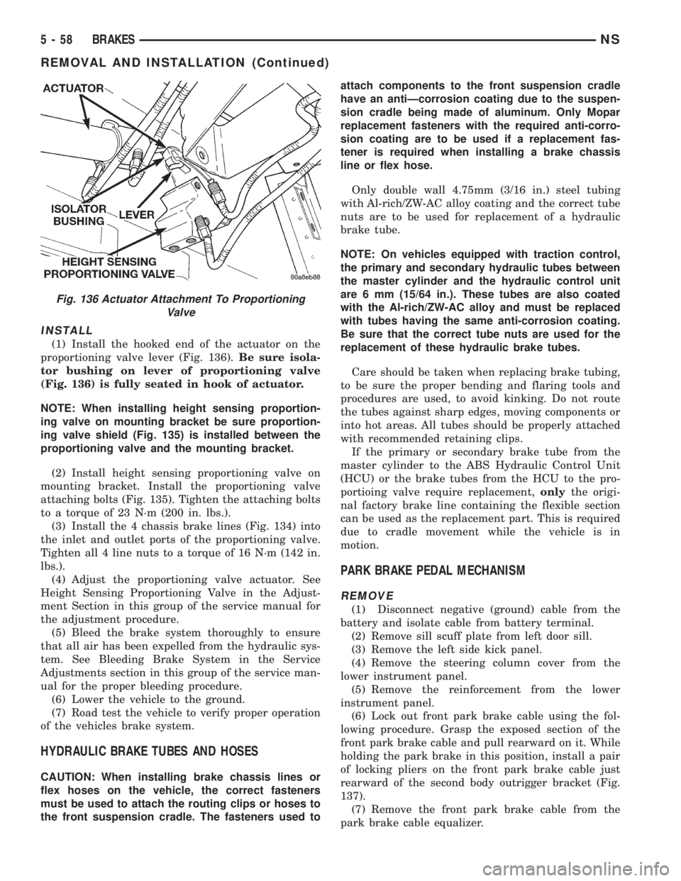
(1) Install the hooked end of the actuator on the
proportioning valve lever (Fig. 136).Be sure isola-
tor bushing on lever of proportioning valve
(Fig. 136) is fully seated in hook of actuator.
NOTE: When installing height sensing proportion-
ing valve on mounting bracket be sure proportion-
ing valve shield (Fig. 135) is installed between the
proportioning valve and the mounting bracket.
(2) Install height sensing proportioning valve on
mounting bracket. Install the proportioning valve
attaching bolts (Fig. 135). Tighten the attaching bolts
to a torque of 23 N´m (200 in. lbs.).
(3) Install the 4 chassis brake lines (Fig. 134) into
the inlet and outlet ports of the proportioning valve.
Tighten all 4 line nuts to a torque of 16 N´m (142 in.
lbs.).
(4) Adjust the proportioning valve actuator. See
Height Sensing Proportioning Valve in the Adjust-
ment Section in this group of the service manual for
the adjustment procedure.
(5) Bleed the brake system thoroughly to ensure
that all air has been expelled from the hydraulic sys-
tem. See Bleeding Brake System in the Service
Adjustments section in this group of the service man-
ual for the proper bleeding procedure.
(6) Lower the vehicle to the ground.
(7) Road test the vehicle to verify proper operation
of the vehicles brake system.
HYDRAULIC BRAKE TUBES AND HOSES
CAUTION: When installing brake chassis lines or
flex hoses on the vehicle, the correct fasteners
must be used to attach the routing clips or hoses to
the front suspension cradle. The fasteners used toattach components to the front suspension cradle
have an antiÐcorrosion coating due to the suspen-
sion cradle being made of aluminum. Only Mopar
replacement fasteners with the required anti-corro-
sion coating are to be used if a replacement fas-
tener is required when installing a brake chassis
line or flex hose.
Only double wall 4.75mm (3/16 in.) steel tubing
with Al-rich/ZW-AC alloy coating and the correct tube
nuts are to be used for replacement of a hydraulic
brake tube.
NOTE: On vehicles equipped with traction control,
the primary and secondary hydraulic tubes between
the master cylinder and the hydraulic control unit
are 6 mm (15/64 in.). These tubes are also coated
with the Al-rich/ZW-AC alloy and must be replaced
with tubes having the same anti-corrosion coating.
Be sure that the correct tube nuts are used for the
replacement of these hydraulic brake tubes.
Care should be taken when replacing brake tubing,
to be sure the proper bending and flaring tools and
procedures are used, to avoid kinking. Do not route
the tubes against sharp edges, moving components or
into hot areas. All tubes should be properly attached
with recommended retaining clips.
If the primary or secondary brake tube from the
master cylinder to the ABS Hydraulic Control Unit
(HCU) or the brake tubes from the HCU to the pro-
portioing valve require replacement,onlythe origi-
nal factory brake line containing the flexible section
can be used as the replacement part. This is required
due to cradle movement while the vehicle is in
motion.
PARK BRAKE PEDAL MECHANISM
REMOVE
(1) Disconnect negative (ground) cable from the
battery and isolate cable from battery terminal.
(2) Remove sill scuff plate from left door sill.
(3) Remove the left side kick panel.
(4) Remove the steering column cover from the
lower instrument panel.
(5) Remove the reinforcement from the lower
instrument panel.
(6) Lock out front park brake cable using the fol-
lowing procedure. Grasp the exposed section of the
front park brake cable and pull rearward on it. While
holding the park brake in this position, install a pair
of locking pliers on the front park brake cable just
rearward of the second body outrigger bracket (Fig.
137).
(7) Remove the front park brake cable from the
park brake cable equalizer.
Fig. 136 Actuator Attachment To Proportioning
Valve
5 - 58 BRAKESNS
REMOVAL AND INSTALLATION (Continued)
Page 146 of 1938
NOTE: When the hold down pin is installed, the
long part of the hold down pin is to be positioned
strait up and down. This will ensure that the hold
down pin is correctly engaged with the adapter.
(6) Install the hold down spring and pin (Fig. 153)
on the leading park brake shoe.
(7) Install the lower return spring (Fig. 152) on
the leading and trailing park brake shoes.When
installing the hold down spring it is to be
installed behind the park brake shoes (Fig.
152).
(8) Install the 4 mounting bolts for the adapter
and hub/bearing into the bolt holes in the axle.
(9) Position the adapter on the 4 mounting bolts
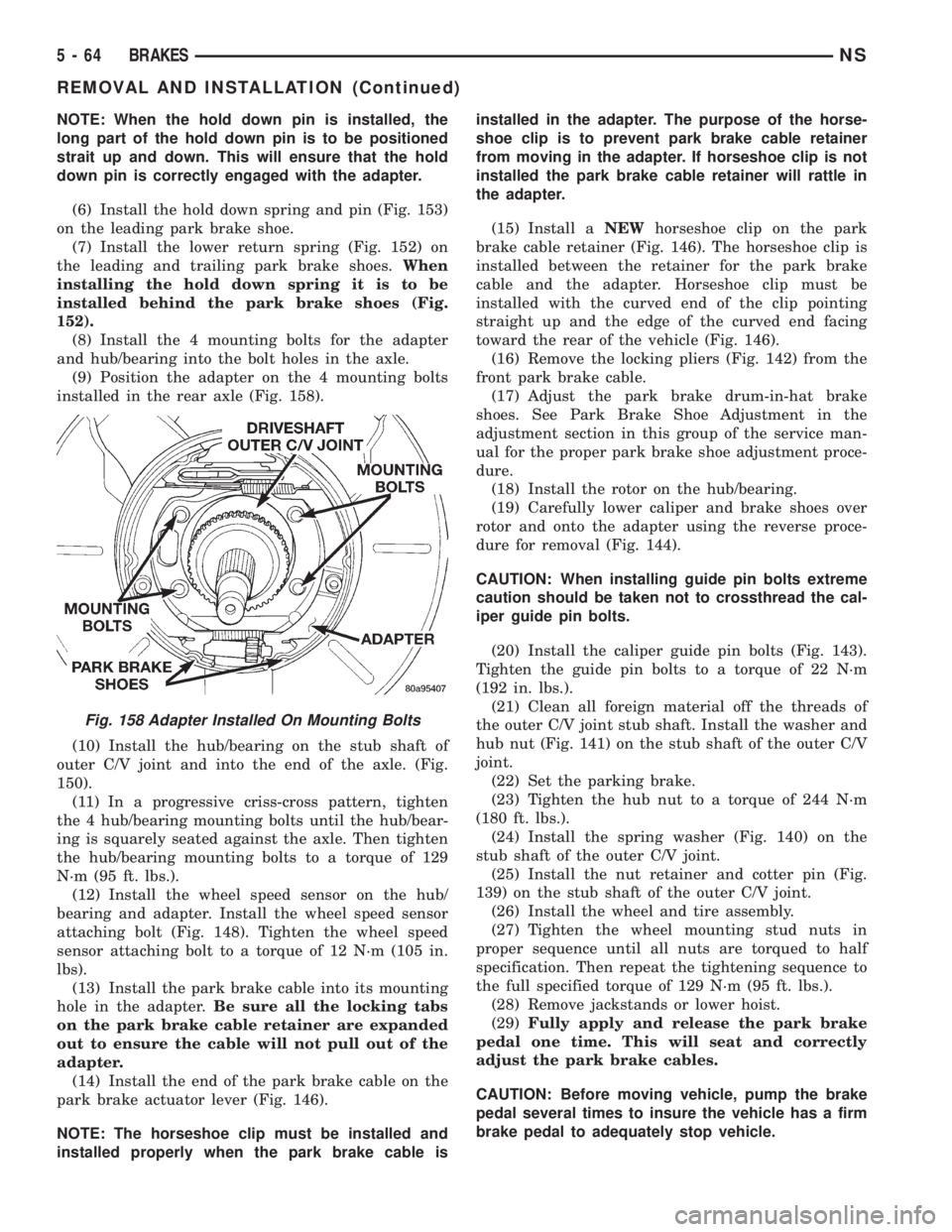
installed in the rear axle (Fig. 158).
(10) Install the hub/bearing on the stub shaft of
outer C/V joint and into the end of the axle. (Fig.
150).
(11) In a progressive criss-cross pattern, tighten
the 4 hub/bearing mounting bolts until the hub/bear-
ing is squarely seated against the axle. Then tighten
the hub/bearing mounting bolts to a torque of 129
N´m (95 ft. lbs.).
(12) Install the wheel speed sensor on the hub/
bearing and adapter. Install the wheel speed sensor
attaching bolt (Fig. 148). Tighten the wheel speed
sensor attaching bolt to a torque of 12 N´m (105 in.
lbs).
(13) Install the park brake cable into its mounting
hole in the adapter.Be sure all the locking tabs
on the park brake cable retainer are expanded
out to ensure the cable will not pull out of the
adapter.
(14) Install the end of the park brake cable on the
park brake actuator lever (Fig. 146).
NOTE: The horseshoe clip must be installed and
installed properly when the park brake cable isinstalled in the adapter. The purpose of the horse-
shoe clip is to prevent park brake cable retainer
from moving in the adapter. If horseshoe clip is not
installed the park brake cable retainer will rattle in
the adapter.
(15) Install aNEWhorseshoe clip on the park
brake cable retainer (Fig. 146). The horseshoe clip is
installed between the retainer for the park brake
cable and the adapter. Horseshoe clip must be
installed with the curved end of the clip pointing
straight up and the edge of the curved end facing
toward the rear of the vehicle (Fig. 146).
(16) Remove the locking pliers (Fig. 142) from the
front park brake cable.
(17) Adjust the park brake drum-in-hat brake
shoes. See Park Brake Shoe Adjustment in the
adjustment section in this group of the service man-
ual for the proper park brake shoe adjustment proce-
dure.
(18) Install the rotor on the hub/bearing.
(19) Carefully lower caliper and brake shoes over
rotor and onto the adapter using the reverse proce-
dure for removal (Fig. 144).
CAUTION: When installing guide pin bolts extreme
caution should be taken not to crossthread the cal-
iper guide pin bolts.
(20) Install the caliper guide pin bolts (Fig. 143).
Tighten the guide pin bolts to a torque of 22 N´m
(192 in. lbs.).
(21) Clean all foreign material off the threads of
the outer C/V joint stub shaft. Install the washer and
hub nut (Fig. 141) on the stub shaft of the outer C/V
joint.
(22) Set the parking brake.
(23) Tighten the hub nut to a torque of 244 N´m
(180 ft. lbs.).
(24) Install the spring washer (Fig. 140) on the
stub shaft of the outer C/V joint.
(25) Install the nut retainer and cotter pin (Fig.
139) on the stub shaft of the outer C/V joint.
(26) Install the wheel and tire assembly.
(27) Tighten the wheel mounting stud nuts in
proper sequence until all nuts are torqued to half
specification. Then repeat the tightening sequence to
the full specified torque of 129 N´m (95 ft. lbs.).
(28) Remove jackstands or lower hoist.
(29)Fully apply and release the park brake
pedal one time. This will seat and correctly
adjust the park brake cables.
CAUTION: Before moving vehicle, pump the brake
pedal several times to insure the vehicle has a firm
brake pedal to adequately stop vehicle.
Fig. 158 Adapter Installed On Mounting Bolts
5 - 64 BRAKESNS
REMOVAL AND INSTALLATION (Continued)
Page 157 of 1938
(12) Inspect caliper piston for pitting, scratches, or
any physical damage. Replace piston if there is evi-
dence of scratches, pitting or physical damage.
CALIPER ASSEMBLY
CAUTION: Excessive vise pressure will cause bore
distortion and binding of piston.
(1) Clamp caliper in a vise (with protective caps
installed on jaws of vise).
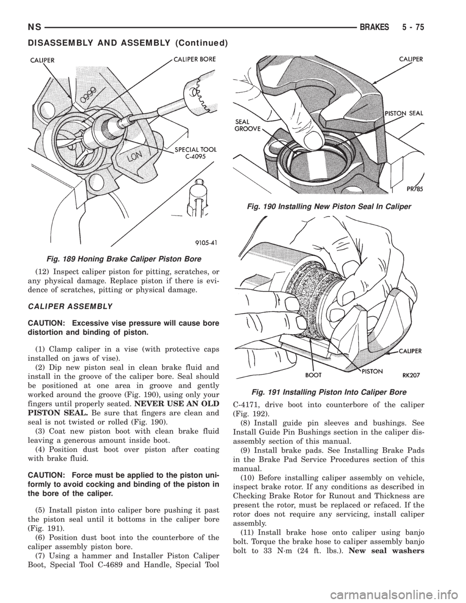
(2) Dip new piston seal in clean brake fluid and
install in the groove of the caliper bore. Seal should
be positioned at one area in groove and gently
worked around the groove (Fig. 190), using only your
fingers until properly seated.NEVER USE AN OLD
PISTON SEAL.Be sure that fingers are clean and
seal is not twisted or rolled (Fig. 190).
(3) Coat new piston boot with clean brake fluid
leaving a generous amount inside boot.
(4) Position dust boot over piston after coating
with brake fluid.
CAUTION: Force must be applied to the piston uni-
formly to avoid cocking and binding of the piston in
the bore of the caliper.
(5) Install piston into caliper bore pushing it past
the piston seal until it bottoms in the caliper bore
(Fig. 191).
(6) Position dust boot into the counterbore of the
caliper assembly piston bore.
(7) Using a hammer and Installer Piston Caliper
Boot, Special Tool C-4689 and Handle, Special ToolC-4171, drive boot into counterbore of the caliper
(Fig. 192).
(8) Install guide pin sleeves and bushings. See
Install Guide Pin Bushings section in the caliper dis-
assembly section of this manual.
(9) Install brake pads. See Installing Brake Pads
in the Brake Pad Service Procedures section of this
manual.
(10) Before installing caliper assembly on vehicle,
inspect brake rotor. If any conditions as described in
Checking Brake Rotor for Runout and Thickness are
present the rotor, must be replaced or refaced. If the
rotor does not require any servicing, install caliper
assembly.
(11) Install brake hose onto caliper using banjo
bolt. Torque the brake hose to caliper assembly banjo
bolt to 33 N´m (24 ft. lbs.).New seal washers
Fig. 189 Honing Brake Caliper Piston Bore
Fig. 190 Installing New Piston Seal In Caliper
Fig. 191 Installing Piston Into Caliper Bore
NSBRAKES 5 - 75
DISASSEMBLY AND ASSEMBLY (Continued)
Page 163 of 1938
group of the service manual for the installation pro-
cedure.
(13) Install wheel and tire.
(14) Tighten the wheel mounting nuts in the
proper sequence until all nuts are torqued to half the
specified torque. Then repeat the tightening sequence
to the full specified torque of 129 N´m (95 ft. lbs.).
(15) Lower vehicle.
(16) Apply and release the park brake pedal one
time. This will seat and correctly adjust the park
brake cables.
CAUTION: Before moving vehicle, pump brake
pedal several times to ensure the vehicle has a firm
enough pedal to stop the vehicle.
(17) Road test the vehicle to ensure proper func-
tion of the vehicle's brake system.
PARK BRAKE CABLE ADJUSTMENT
The park brake cables on this vehicle have an
automatic self adjuster built into the park brake
pedal mechanism. When the foot operated park brake
pedal is in its released (upward most) position, a
clock spring automatically adjusts the park brake
cables. The park brake cables are adjusted (ten-
sioned) just enough to remove all the slack from the
cables. The automatic adjuster system will not over
adjust the cables causing rear brake drag.
Due to the automatic adjust feature of the park
brake pedal, adjustment of the parking brake cables
on these vehicles relies on proper drum brake and
park brake shoe adjustment. See Rear Brake Adjust-
ment and Park Brake Shoe Adjustment in the Ser-
vice Adjustments Section in this group of the service
manual.
When the park brake pedal is applied the self
adjuster is by-passed and the pedal operates nor-
mally to engage the park brakes.
When a service procedure needs to be performed on
the park brake pedal or the park brake cables, the
automatic self adjuster can be manually locked out
by the service technician.
PROPORTIONING VALVE (HEIGHT SENSING)
Proportioning valve actuator adjustment will be
required if there is a complaint of premature rear
wheel lockup and the front and rear brake shoe lin-
ings checked OK during inspection, the height sens-
ing proportioning valve required replacement, or
there is a complaint of excessive pedal effort and the
vacuum booster and brake pedal checked OK. Make
sure the proportioning valve and the mounting
bracket are firmly attached to the vehicle. Then, pro-
ceed with the following procedure to perform the
adjustment of the actuator.(1) Raise vehicle. Vehicle is to be raised and sup-
ported on jackstands or with a frame contact type
hoist so the rear suspension of the vehicle is hanging
free. See hoisting in the Lubrication And Mainte-
nance section of this service manual.
(2) Remove rear wheels/tires.
(3) Using an appropriate jack, support the rear
axle prior to the removal of the track bar and shock
absorber bolts from the rear axle.
(4) Unbolt the track bar from the rear axle.
(5) Unbolt both shock absorbers from the rear
axle.
(6) Loosen (do not remove) both of the leaf spring
to front spring hanger pivot bolts.
NOTE: When lowering the rear axle be sure that the
leaf springs do not come in contact with the hoist
limiting the downward movement of the axle. If this
occurs an improper adjustment of the actuator may
result.
(7) Lower the rear axle so it is at its farthest point
of downward movement.
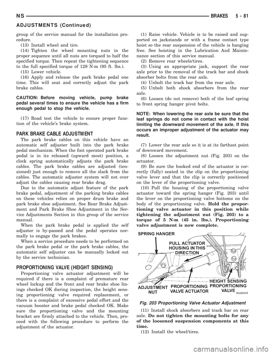
(8) Loosen the adjustment nut (Fig. 203) on the
actuator.
(9) Be sure the hooked end of the actuator is cor-
rectly (fully) seated in the clip on the proportioning
valve lever and that the clip is correctly positioned
on the lever of the proportioning valve.
(10) Pull the housing of the proportioning valve
actuator toward the spring hanger (Fig. 203) until
the lever on the proportioning valve bottoms on the
body of the proportioning valve.Hold the propor-
tioning valve actuator in this position while
tightening the adjustment nut (Fig. 203) to a
torque of 5 N´m (45 in. lbs.). Proportioning
valve adjustment is now complete.
(11) Install shock absorbers and track bar on rear
axle.Do not tighten the mounting bolts for any
of the loosened suspension components at this
time.
(12) Install the wheel/tires.
Fig. 203 Proportioning Valve Actuator Adjustment
NSBRAKES 5 - 81
ADJUSTMENTS (Continued)
Page 164 of 1938
(13) Lower the vehicle to the ground.Be sure
that the suspension is supporting the full
weight of the vehicle.
(14) Tighten the spring to front hanger pivot bolts
to a torque of 156 N´m (115 ft. lbs.).
(15) Tighten the shock absorber mounting bolts to
a torque of 101 N´m (75 ft. lbs.).
(16) Tighten the track bar mounting bolt to a
torque of 95 N´m (70 ft. lbs.).
(17) Road test vehicle to ensure that the prema-
ture rear wheel lockup condition has been corrected.
SPECIFICATIONS
BRAKE FLUID
The brake fluid used in this vehicle must conform
to DOT 3 specifications and SAE J1703 standards.No other type of brake fluid is recommended or
approved for usage in the vehicle brake system. Use
only Mopar brake fluid or an equivalent from a
tightly sealed container.
CAUTION: Never use reclaimed brake fluid or fluid
from an container which has been left open. An
open container will absorb moisture from the air
and contaminate the fluid.
CAUTION: Never use any type of a petroleum-
based fluid in the brake hydraulic system. Use of
such type fluids will result in seal damage of the
vehicle brake hydraulic system causing a failure of
the vehicle brake system. Petroleum based fluids
would be items such as engine oil, transmission
fluid, power steering fluid ect.
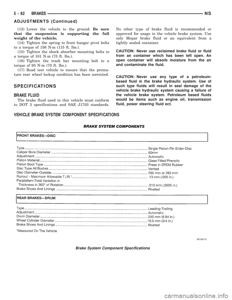
VEHICLE BRAKE SYSTEM COMPONENT SPECIFICATIONS
Brake System Component Specifications
5 - 82 BRAKESNS
ADJUSTMENTS (Continued)
Page 165 of 1938
BRAKE ACTUATION SYSTEM
ACTUATION:
Vacuum Operated Power Brakes.........Standard
Hydraulic System...........Dual-Diagonally Split
Antilock Brake Sytem (Teves Mark-20)...........
MASTER CYLINDER ASSEMBLY:
Supplier..............................Bosch
Type For Non-ABSAnd
ABS Brakes. . . .Conventional Compensating Port
Type For ABS Brakes
With Traction Control . . .Dual Center Port Design
Body Material...............Anodized Aluminum
Reservoir Material................Polypropelene
MASTER CYLINDER BORE /
STROKE AND SPLIT:
ABS W/Disc/Drum Brakes......23.8 mm x 36 mm
(.937 in. x 1.47 in.)
AWD W/Disc/Disc Brakes........25.4 mm x 39 mm
(1.00 in. x 1.50 in.)
Displacement Split.....................50/50
MASTER CYLINDER FLUID OUTLET PORTS:
Non-ABS And ABS . . .Primary 7/16±24 Secondary 7/
16±24
ABS With Traction Control.......Primary M12 x 1
Secondary M12 x 1
Outlet Fitting Type Non-ABS
AndABS...........Double Wall Inverted Flare
Outlet Fitting Type ABS With
Traction Control...................ISO Flare
ABS HYDRAULIC CONTROL UNIT:
Hydraulic Tube Fitting Type............ISO Flare
BOOSTER:
Make/Type.................Bosch Vacuum Assist
Mounting Studs.....................M8x1.25
Type .........................270 ZLT RSMV
Boost At 20 inches Of
Manifold Vacuum...........3800 N´m (850 lbs.)
PROPORTIONING VALVE:
Material...........................Aluminum
Function....................Hydraulic Pressure
Proportioning To Rear Brakes
BRAKE PEDAL
Pedal Ratio.............................3.36
BRAKE FASTENER TORQUE SPECIFICATIONS
DESCRIPTION TORQUE
BRAKE TUBES:
Tube Nuts To Fittings And
Components..............17N´m(145 in. lbs.)
BRAKE HOSE:
To Caliper Banjo Bolt..........48N´m(35ft.lbs.)
Intermediate Bracket.........12N´m(105 in. lbs.)
MASTER CYLINDER:
To Vacuum Booster
Mounting Nut............25N´m(225 in. lbs.)
FIXED PROPORTIONING VALVE:
To Frame Rail Attaching
Bolts....................14N´m(125 in. lbs.)
HEIGHT SENSING PROPORTIONING VALVE:
To Mounting Bracket
Attaching Bolts...........23N´m(200 in. lbs.)
Actuator Assembly
Adjustment Nut.............5N´m(45in.lbs.)
Mounting Bracket To Frame
Rail Bolts................17N´m(150 in. lbs.)
JUNCTION BLOCK (NON-ABS BRAKES)
To Suspension Cradle
Mounting Bolt............28N´m(250 in. lbs.)
VACUUM BOOSTER:
To Dash Panel Mounting
Nuts....................28N´m(250 in. lbs.)
REAR WHEEL CYLINDER:
To Support Plate Mounting
Bolts.....................8N´m(75in.lbs.)
Bleeder Screw...............10N´m(80in.lbs.)
BRAKE SUPPORT PLATE:
To Rear Axle Mounting Bolts . . .130 N´m (95 ft. lbs.)
DISC BRAKE CALIPER:
Guide Pin Bolts..............41N´m(30ft.lbs.)
Bleeder Screw..............15N´m(125 in. lbs.)
ABS HYDRAULIC CONTROL UNIT:
Mounting Bracket To
Suspension Cradle Bolts.....28N´m(250 in. lbs.)
To Mounting Bracket Isolator
Attaching Bolts............11N´m(97in.lbs.)
CAB To HCU Mounting Screws . . .2 N´m (17 in. lbs.)
WHEEL SPEED SENSOR:
To Axle Or Steering Knuckle
Mounting Bolt............12N´m(105 in. lbs.)
PARKING BRAKE:
Pedal Assembly Mounting
Bolts....................28N´m(250 in. lbs.)
REAR HUB AND BEARING:
To Axle Mounting Bolts........129 N´m (95 ft. lbs.)
WHEEL:
Stud Lug Nut........115±156 N´m (84-115 ft. lbs.)
NSBRAKES 5 - 83
SPECIFICATIONS (Continued)
Page 167 of 1938
ANTILOCK BRAKE SYSTEM ± TEVES MARK-20
INDEX
page page
DESCRIPTION AND OPERATION
ABS BRAKE SYSTEM COMPONENTS........ 87
ABS BRAKES COMPONENT
ABBREVIATION LIST.................... 85
ABS BRAKES OPERATION AND VEHICLE
PERFORMANCE....................... 86
ABS FUSES............................ 89
ABS MASTER CYLINDER AND POWER
BRAKE BOOSTER..................... 87
ABS RELAYS........................... 89
ABS WARNING LAMP (YELLOW)............ 91
ANTILOCK BRAKES OPERATION
DESCRIPTION........................ 85
ASR VALVE (ABS WITH TRACTION
CONTROL ONLY)...................... 88
CONTROLLER ANTILOCK BRAKES (CAB)..... 90
HCU BRAKE FLUID ACCUMULATORS AND
NOISE DAMPING CHAMBER............. 88
HCU PUMP/MOTOR..................... 89
HYDRAULIC CIRCUITS AND VALVE
OPERATION.......................... 92
INLET VALVES AND SOLENOIDS............ 88
INTEGRATED CONTROL UNIT (ICU)......... 87
OUTLET VALVES AND SOLENOIDS.......... 88
PROPORTIONING VALVES................ 89
WHEEL SPEED SENSORS................. 89
DIAGNOSIS AND TESTING
ABS BRAKE DIAGNOSTIC TOOL
CONNECTOR......................... 96
ABS DIAGNOSTIC TROUBLE CODES........ 97
ABS DIAGNOSTICS MANUAL.............. 96ABS GENERAL DIAGNOSTICS
INFORMATION........................ 95
ABS SERVICE PRECAUTIONS.............. 99
ABS SYSTEM SELF DIAGNOSTICS.......... 96
ABS WIRING DIAGRAM INFORMATION....... 95
BRAKE FLUID CONTAMINATION............ 98
DRB DIAGNOSTIC SCAN TOOL USAGE...... 96
INTERMITTENT DIAGNOSTIC TROUBLE
CODES.............................. 97
PROPORTIONING VALVE................. 98
TEST DRIVING ABS COMPLAINT VEHICLE.... 98
TONEWHEEL INSPECTION................ 98
SERVICE PROCEDURES
BLEEDING TEVES MARK 20 HYDRAULIC
SYSTEM............................. 99
BRAKE FLUID LEVEL INSPECTION.......... 99
REMOVAL AND INSTALLATION
ABS GENERAL SERVICE PRECAUTIONS.... 100
CONTROLLER ANTILOCK BRAKES (CAB).... 103
HYDRAULIC CONTROL UNIT.............. 100
TONE WHEEL (REAR AWD)............... 111
TONE WHEEL (REAR FWD)............... 110
WHEEL SPEED SENSOR (FRONT)......... 105
WHEEL SPEED SENSOR (REAR AWD)...... 108
WHEEL SPEED SENSOR (REAR FWD)...... 106
SPECIFICATIONS
BRAKE FASTENER TORQUE
SPECIFICATIONS..................... 112
SPEED SENSOR TONE WHEEL RUNOUT.... 112
WHEEL SPEED SENSOR TO TONE
WHEEL CLEARANCE.................. 112
DESCRIPTION AND OPERATION
ANTILOCK BRAKES OPERATION DESCRIPTION
The purpose of an Antilock Brake System (ABS) is to
prevent wheel lock-up under braking conditions on virtu-
ally any type of road surface. Antilock Braking is desirable
because a vehicle which is stopped without locking the
wheels will retain directional stability and some steering
capability. This allows the driver to retain greater control
of the vehicle during braking.
This section of the service manual covers the description
and on car service for the ITT Teves Mark 20 ABS Brake
System and the ITT Teves Mark 20 ABS Brake System
with Traction Control. If other service is required on the
non ABS related components of the brake system, refer to
the appropriate section in this group of the service manual
for the specific service procedure required.
ABS BRAKES COMPONENT ABBREVIATION LIST
In this section of the service manual, several
abbreviations are used for the components of the
Teves Mark 20 ABS Brake System and the Teves
Mark 20 ABS Brake System with Traction Control.
They are listed below for your reference.
²CAB±Controller Antilock Brake
²ICU±Integrated Control Unit
²HCU±Hydraulic Control Unit
²TCS±Traction Control
²ABS±Antilock Brake System
²PSI±Pounds Per Square Inch (pressure)
²WSS±Wheel Speed Sensor
²FWD±Front Wheel Drive
²AWD±All Wheel Drive
²DTC±Diagnostic Trouble Code
NSBRAKES 5 - 85
Page 182 of 1938
If the brake system is to be bled using pressurized
bleeding equipment, refer to Bleeding Brake System
in the Service Adjustments section at the beginning
of this group for proper equipment usage and proce-
dures.
(1) Assemble and install all brake system compo-
nents on the vehicle making sure all hydraulic fluid
lines are installed and properly torqued.
(2) Connect the DRB Diagnostics Tester to the
diagnostics connector. The Teves Mark 20 ABS diag-
nostic connector is located under the instrument
panel to the left of the steering column cover.
(3) Using the DRB, check to make sure the CAB
does not have any fault codes stored. If it does,
remove them using the DRB.
WARNING: WHEN BLEEDING THE BRAKE SYS-
TEM WEAR SAFETY GLASSES. A CLEAR BLEED
TUBE MUST BE ATTACHED TO THE BLEEDER
SCREWS AND SUBMERGED IN A CLEAR CON-
TAINER FILLED PART WAY WITH CLEAN BRAKE
FLUID. DIRECT THE FLOW OF BRAKE FLUID AWAY
FROM THE PAINTED SURFACES OF THE VEHICLE.
BRAKE FLUID AT HIGH PRESSURE MAY COME
OUT OF THE BLEEDER SCREWS WHEN OPENED.
(4) Bleed the base brake system using the stan-
dard pressure or manual bleeding procedure as out-
lined in the Service Adjustments section of this
service manual.
(5) Using the DRB, go to the9Bleed ABS9routine.
Apply the brake pedal firmly and initiate the9Bleed
ABS9cycle one time. Release the brake pedal.
(6) Bleed the base brake system again, as in step
Step 4 above.
(7) Repeat steps Step 5 and Step 6 above until
brake fluid flows clear and is free of any air bubbles.
Check brake fluid level in reservoir periodically to
prevent reservoir from running low on brake fluid.
(8) Test drive the vehicle to be sure brakes are
operating correctly and that brake pedal is solid.
REMOVAL AND INSTALLATION
ABS GENERAL SERVICE PRECAUTIONS
CAUTION: Review this entire section prior to per-
forming any mechanical work on a vehicle equipped
with the ITT Tevis Mark 20 ABS brake system. This
section contains information on precautions per-
taining to potential component damage, vehicle
damage and personal injury which could result
when servicing an ABS equipped vehicle.
CAUTION: Only the recommended jacking or hoist-
ing positions for this vehicle are to be used when-ever it is necessary to lift a vehicle. Failure to raise
a vehicle from the recommended locations could
result in lifting a vehicle by the hydraulic control
unit mounting bracket. Lifting a vehicle by the
hydraulic control unit mounting bracket will result
in damage to the mounting bracket and the hydrau-
lic control unit.
CAUTION: Certain components of the ABS System
are not intended to be serviced individually.
Attempting to remove or disconnect certain system
components may result in improper system opera-
tion. Only those components with approved
removal and installation procedures in this manual
should be serviced.
CAUTION: Brake fluid will damage painted sur-
faces. If brake fluid is spilled on any painted sur-
faces, wash off with water immediately.
CAUTION: When performing any service procedure
on a vehicle equipped with ABS do not apply a 12
volt power source to the ground circuit of the pump
motor in the CAB. Doing this will damage the pump
motor and will require replacement of the HCU.
The following are general cautions which should be
observed when servicing the ABS system and/or
other vehicle systems. Failure to observe these pre-
cautions may result in ABS System component dam-
age.
If welding work is to be performed on the vehicle,
using an electric arc welder, the CAB connector
should be disconnected during the welding operation.
The CAB 25 way connector connector should never
be connected or disconnected with the ignition switch
in the ON position.
Many components of the ABS System are not ser-
viceable and must be replaced as an assembly. Do not
disassemble any component which is not designed to
be serviced.
HYDRAULIC CONTROL UNIT
REMOVE
(1) Disconnect the negative (ground) cable from
the battery and isolate cable.
(2) Using a brake pedal depressor, move and lock
the brake pedal to a position past the first inch of
pedal travel.This will prevent brake fluid from
draining out of the master cylinder when the
brake tubes are removed from the HCU.
(3) Raise vehicle. Vehicle is to be raised and sup-
ported on jackstands or on a frame contact type
5 - 100 BRAKESNS
SERVICE PROCEDURES (Continued)
Page 184 of 1938
INSTALL
(1) Install the CAB (Fig. 19) on the bottom of the
HCU. Refer to Controller Antilock Brakes (CAB) in
the Removal And Installation Section in this group of
the service manual for the required procedure.
(2) Install the HCU on the mounting bracket (Fig.
23). Install the 3 bolts (Fig. 23) attaching the HCU to
the mounting bracket. Tighten the 3 mounting bolts
to a torque of 11 N´m (97 in. lbs.).
CAUTION: The HCU mounting bracket to front sus-
pension cradle mounting bolts have a unique corro-
sion protection coating and a special aluminum
washer. For this reason, only the original, or origi-
nal equipment Mopar replacement bolts can be
used to mount the HCU bracket to the front suspen-
sion crossmember.
(3) Install the HCU and its mounting bracket as
an assembly on the front suspension crossmember.
Install the 3 bolts attaching the HCU bracket to the
crossmember (Fig. 22). Tighten the 3 mounting bolts
to a torque of 28 N´m (250 in. lbs.).
CAUTION: Because of the flexible section in the
primary and secondary brake tubes, and the brake
tubes between the HCU and the proportioning
valve, the brake tubes must be held in proper ori-
entation when tightened and torqued. These tubes
must not contact each other or other vehicle com-
ponents when installed. Also, after the brake tubes
are installed on the HCU, ensure all spacer clips are
reinstalled on the brake tubes.
CAUTION: When installing the chassis brake tubes
on the HCU valve block, they must be located cor-
rectly in the valve block to ensure proper ABS oper-
ation. Refer to (Fig. 21) for the correct chassis
brake tube locations.NOTE: The chassis brake tube attachment loca-
tions to the HCU, are marked on the bottom of the
HCU mounting bracket.
(4) Install the 6 chassis brake tubes into their cor-
rect port locations on the HCU valve block as shown
in (Fig. 21). Tighten the tube nuts to a torque of 17
N´m (145 in. lbs.).
NOTE: Before installing the 25 way connector in
the CAB be sure the seal is properly installed in the
connector.
(5) Install the 25 way connector (Fig. 19) on the
CAB using the following procedure. Position the 25
way connector in the socket of the CAB and carefully
push it down as far as possible. When connector is
fully seated by hand into the CAB socket, push in the
connector lock (Fig. 20). This will pull the connector
into the socket of the CAB and lock it in the installed
position.
NOTE: The CAB wiring harness must be clipped to
the HCU mounting bracket. This will ensure the wir-
ing harness is properly routed and does not contact
the brake tubes or the body of the vehicle.
(6) Clip the cab wiring harness (Fig. 19) to the
HCU mounting bracket.
(7) Install the routing clips (Fig. 24) on the brake
tubes.
(8) Lower vehicle.
(9) Connect negative cable back on negative post of
the battery.
(10) Bleed the base brakes and the ABS brakes
hydraulic system. Refer to the Bleeding ABS System
in this section of the manual for the proper bleeding
procedure.
(11) Road test vehicle to ensure proper operation of
the base and ABS systems.
Fig. 23 HCU Mounting Bolts
Fig. 24 Brake Tube Routing Clips
5 - 102 BRAKESNS
REMOVAL AND INSTALLATION (Continued)