servo CHRYSLER VOYAGER 1996 Repair Manual
[x] Cancel search | Manufacturer: CHRYSLER, Model Year: 1996, Model line: VOYAGER, Model: CHRYSLER VOYAGER 1996Pages: 1938, PDF Size: 55.84 MB
Page 1267 of 1938
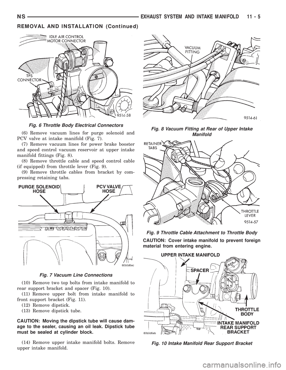
(6) Remove vacuum lines for purge solenoid and
PCV valve at intake manifold (Fig. 7).
(7) Remove vacuum lines for power brake booster
and speed control vacuum reservoir at upper intake
manifold fittings (Fig. 8).
(8) Remove throttle cable and speed control cable
(if equipped) from throttle lever (Fig. 9).
(9) Remove throttle cables from bracket by com-
pressing retaining tabs.
(10) Remove two top bolts from intake manifold to
rear support bracket and spacer (Fig. 10).
(11) Remove upper bolt from intake manifold to
front support bracket (Fig. 11).
(12) Remove dipstick.
(13) Remove dipstick tube.
CAUTION: Moving the dipstick tube will cause dam-
age to the sealer, causing an oil leak. Dipstick tube
must be sealed at cylinder block.
(14) Remove upper intake manifold bolts. Remove
upper intake manifold.CAUTION: Cover intake manifold to prevent foreign
material from entering engine.
Fig. 6 Throttle Body Electrical Connectors
Fig. 7 Vacuum Line Connections
Fig. 8 Vacuum Fitting at Rear of Upper Intake
Manifold
Fig. 9 Throttle Cable Attachment to Throttle Body
Fig. 10 Intake Manifold Rear Support Bracket
NSEXHAUST SYSTEM AND INTAKE MANIFOLD 11 - 5
REMOVAL AND INSTALLATION (Continued)
Page 1268 of 1938
INSTALLATION
(1) Install new upper intake manifold gasket.
NOTE: Center outboard fastener is a double stud.
(2) Tighten upper intake manifold fasteners start-
ing at center and progressing outward in both direc-
tions. Tighten bolts to 28 N´m (250 in. lbs.). Repeat
this procedures until all fasteners are at specified
torque.
(3) Install dipstick tube. Seal tube to cylinder
block using MopartStud N' Bearing Mount Adhe-
sive. Tighten dipstick tube fastener to 12 N´m (105
in. lbs.)
(4) Install dipstick.
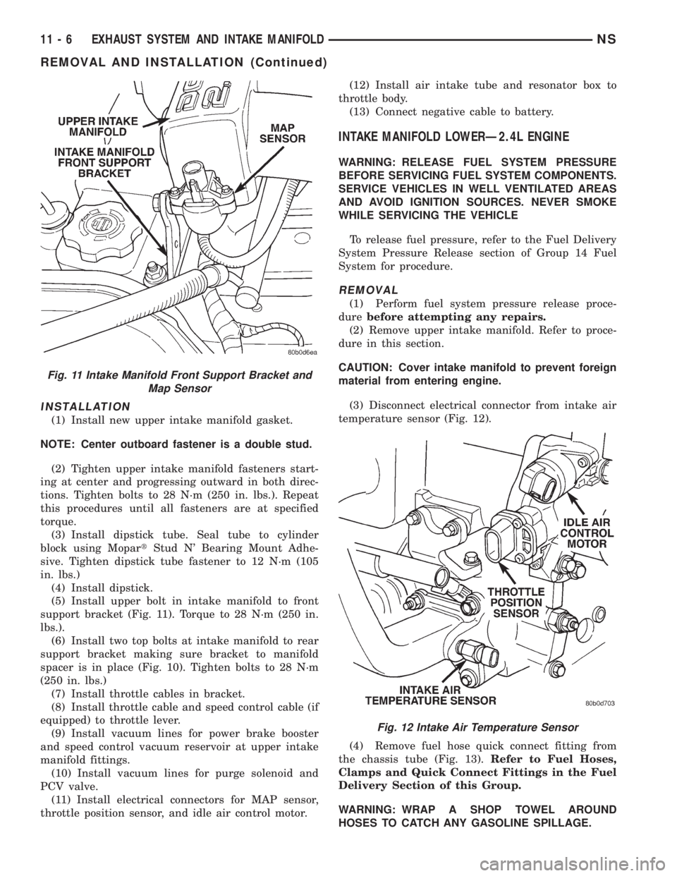
(5) Install upper bolt in intake manifold to front
support bracket (Fig. 11). Torque to 28 N´m (250 in.
lbs.).
(6) Install two top bolts at intake manifold to rear
support bracket making sure bracket to manifold
spacer is in place (Fig. 10). Tighten bolts to 28 N´m
(250 in. lbs.)
(7) Install throttle cables in bracket.
(8) Install throttle cable and speed control cable (if
equipped) to throttle lever.
(9) Install vacuum lines for power brake booster
and speed control vacuum reservoir at upper intake
manifold fittings.
(10) Install vacuum lines for purge solenoid and
PCV valve.
(11) Install electrical connectors for MAP sensor,
throttle position sensor, and idle air control motor.(12) Install air intake tube and resonator box to
throttle body.
(13) Connect negative cable to battery.
INTAKE MANIFOLD LOWERÐ2.4L ENGINE
WARNING: RELEASE FUEL SYSTEM PRESSURE
BEFORE SERVICING FUEL SYSTEM COMPONENTS.
SERVICE VEHICLES IN WELL VENTILATED AREAS
AND AVOID IGNITION SOURCES. NEVER SMOKE
WHILE SERVICING THE VEHICLE
To release fuel pressure, refer to the Fuel Delivery
System Pressure Release section of Group 14 Fuel
System for procedure.
REMOVAL
(1) Perform fuel system pressure release proce-
durebefore attempting any repairs.
(2) Remove upper intake manifold. Refer to proce-
dure in this section.
CAUTION: Cover intake manifold to prevent foreign
material from entering engine.
(3) Disconnect electrical connector from intake air
temperature sensor (Fig. 12).
(4) Remove fuel hose quick connect fitting from
the chassis tube (Fig. 13).Refer to Fuel Hoses,
Clamps and Quick Connect Fittings in the Fuel
Delivery Section of this Group.
WARNING: WRAP A SHOP TOWEL AROUND
HOSES TO CATCH ANY GASOLINE SPILLAGE.
Fig. 11 Intake Manifold Front Support Bracket and
Map Sensor
Fig. 12 Intake Air Temperature Sensor
11 - 6 EXHAUST SYSTEM AND INTAKE MANIFOLDNS
REMOVAL AND INSTALLATION (Continued)
Page 1298 of 1938
FUEL DELIVERY SYSTEM
INDEX
page page
DESCRIPTION AND OPERATION
FUEL DELIVERY SYSTEM.................. 4
FUEL INJECTORS........................ 5
FUEL LEVEL SENSOR..................... 5
FUEL PRESSURE REGULATOR.............. 5
FUEL PUMP MODULE..................... 4
FUEL TANK............................. 5
PRESSURE-VACUUM FILLER CAP........... 6
QUICK-CONNECT FITTINGS................ 6
DIAGNOSIS AND TESTING
FUEL INJECTORS........................ 9
FUEL LEVEL SENSOR..................... 9
FUEL PUMP PRESSURE TEST 2.4/3.3/3.8L..... 6
SERVICE PROCEDURES
FUEL SYSTEM PRESSURE RELEASE
PROCEDUREÐ2.4/3.3/3.8L............... 11
FUEL SYSTEM PRESSURE RELEASE
PROCEDUREÐ3.0L ENGINE............. 11
HOSES AND CLAMPS.................... 12QUICK-CONNECT FITTINGS............... 12
REMOVAL AND INSTALLATION
ACCELERATOR PEDAL................... 26
FUEL FILTER........................... 12
FUEL INJECTOR RAILÐ2.4L............... 18
FUEL INJECTOR RAILÐ3.0L............... 19
FUEL INJECTOR RAILÐ3.3/3.8L............ 21
FUEL INJECTORSÐ3.0L.................. 25
FUEL INJECTORÐ2.4L................... 24
FUEL INJECTORÐ3.3/3.8L................. 26
FUEL LEVEL SENSOR.................... 15
FUEL PRESSURE REGULATOR............. 14
FUEL PUMP INLET STRAINER............. 15
FUEL PUMP MODULE.................... 13
FUEL TANK............................ 17
THROTTLE CABLE...................... 27
SPECIFICATIONS
FUEL TANK CAPACITY................... 28
TORQUE.............................. 28
DESCRIPTION AND OPERATION
FUEL DELIVERY SYSTEM
The front wheel drive van uses a plastic fuel tank
located on the left side of the vehicle.
The Fuel Delivery System consists of: the electric
fuel pump module, fuel filter, tubes/lines/hoses, fuel
rail, and fuel injectors.
The in-tank fuel pump module contains the fuel
pump and pressure regulator. The pump is serviced
as part of the fuel pump module. Refer to Fuel Pump
Module.
The fuel filter is a replaceable in-line filter. The fil-
ter attaches to a bracket mounted on top of the fuel
tank. Refer to the Maintenance Schedules in the
Introduction section of this manual for recommended
fuel filter replacement intervals.
A returnless fuel system is used on all vehicles.
Fuel is returned through the fuel pump module and
back to the fuel tank. A separate fuel return line
from the tank to the engine is no longer used.
FUEL PUMP MODULE
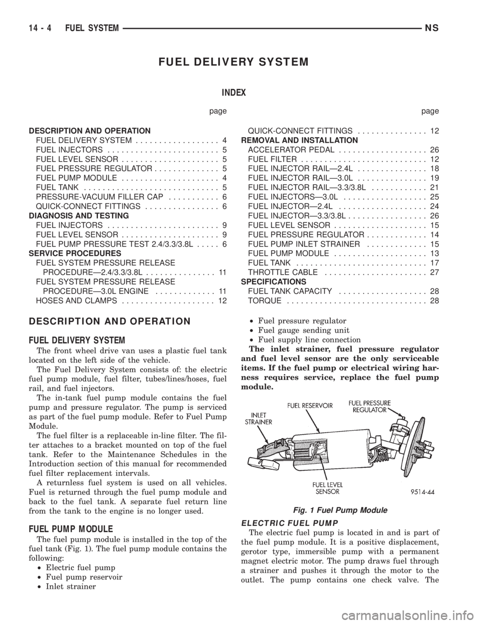
The fuel pump module is installed in the top of the
fuel tank (Fig. 1). The fuel pump module contains the
following:
²Electric fuel pump
²Fuel pump reservoir
²Inlet strainer²Fuel pressure regulator
²Fuel gauge sending unit
²Fuel supply line connection
The inlet strainer, fuel pressure regulator
and fuel level sensor are the only serviceable
items. If the fuel pump or electrical wiring har-
ness requires service, replace the fuel pump
module.
ELECTRIC FUEL PUMP
The electric fuel pump is located in and is part of
the fuel pump module. It is a positive displacement,
gerotor type, immersible pump with a permanent
magnet electric motor. The pump draws fuel through
a strainer and pushes it through the motor to the
outlet. The pump contains one check valve. The
Fig. 1 Fuel Pump Module
14 - 4 FUEL SYSTEMNS
Page 1307 of 1938
WARNING: RELEASE FUEL SYSTEM PRESSURE
BEFORE DISCONNECTING QUICK-CONNECT FIT-
TINGS AT FUEL FILTER. REFER TO THE FUEL
PRESSURE RELEASE PROCEDURE.
REMOVAL
(1) Perform fuel system pressure release.
(2) Disconnect quick-connect fittings from fuel
pump module and chassis fuel supply tube. Refer to
Quick-Connect Fittings in this section.
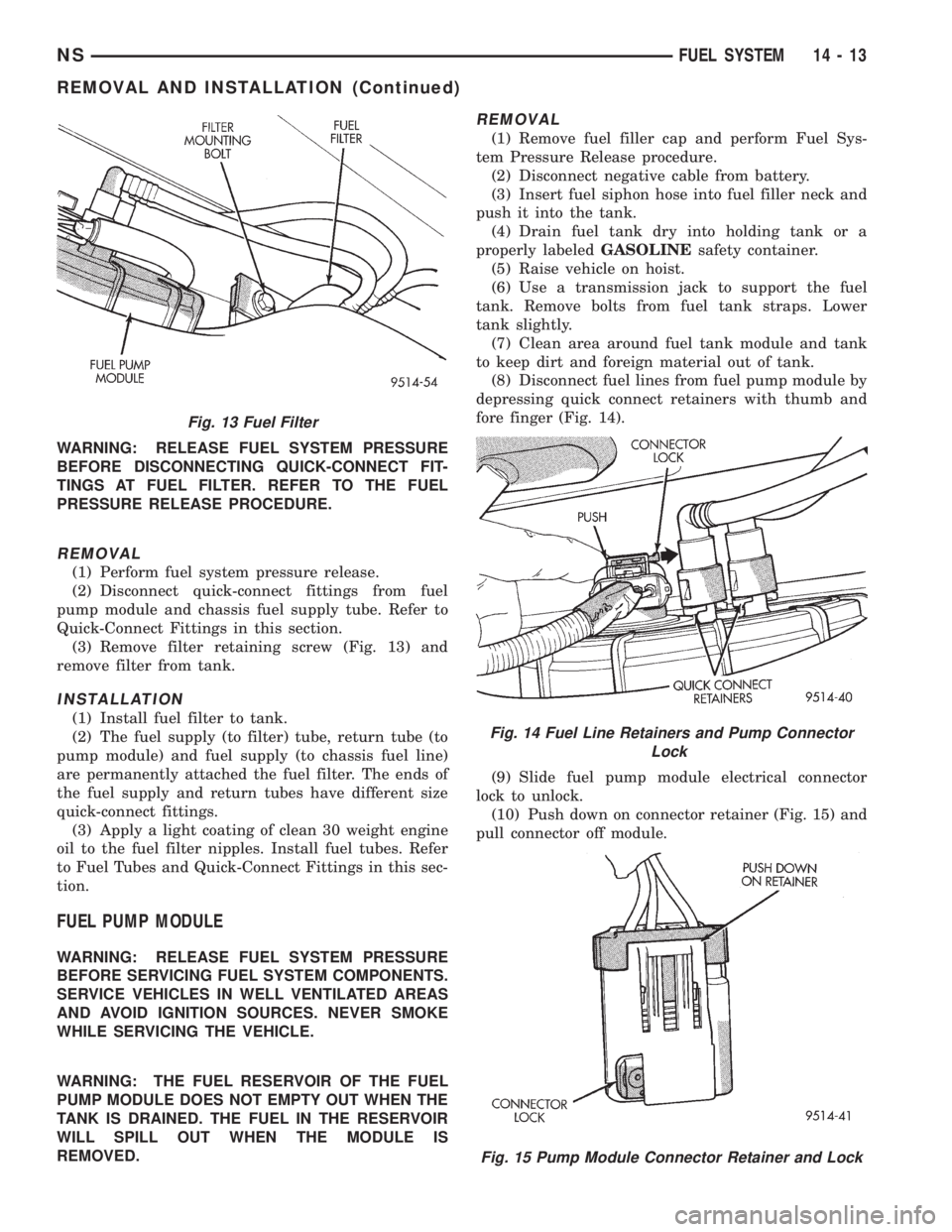
(3) Remove filter retaining screw (Fig. 13) and
remove filter from tank.
INSTALLATION
(1) Install fuel filter to tank.
(2) The fuel supply (to filter) tube, return tube (to
pump module) and fuel supply (to chassis fuel line)
are permanently attached the fuel filter. The ends of
the fuel supply and return tubes have different size
quick-connect fittings.
(3) Apply a light coating of clean 30 weight engine
oil to the fuel filter nipples. Install fuel tubes. Refer
to Fuel Tubes and Quick-Connect Fittings in this sec-
tion.
FUEL PUMP MODULE
WARNING: RELEASE FUEL SYSTEM PRESSURE
BEFORE SERVICING FUEL SYSTEM COMPONENTS.
SERVICE VEHICLES IN WELL VENTILATED AREAS
AND AVOID IGNITION SOURCES. NEVER SMOKE
WHILE SERVICING THE VEHICLE.
WARNING: THE FUEL RESERVOIR OF THE FUEL
PUMP MODULE DOES NOT EMPTY OUT WHEN THE
TANK IS DRAINED. THE FUEL IN THE RESERVOIR
WILL SPILL OUT WHEN THE MODULE IS
REMOVED.
REMOVAL
(1) Remove fuel filler cap and perform Fuel Sys-
tem Pressure Release procedure.
(2) Disconnect negative cable from battery.
(3) Insert fuel siphon hose into fuel filler neck and
push it into the tank.
(4) Drain fuel tank dry into holding tank or a
properly labeledGASOLINEsafety container.
(5) Raise vehicle on hoist.
(6) Use a transmission jack to support the fuel
tank. Remove bolts from fuel tank straps. Lower
tank slightly.
(7) Clean area around fuel tank module and tank
to keep dirt and foreign material out of tank.
(8) Disconnect fuel lines from fuel pump module by
depressing quick connect retainers with thumb and
fore finger (Fig. 14).
(9) Slide fuel pump module electrical connector
lock to unlock.
(10) Push down on connector retainer (Fig. 15) and
pull connector off module.
Fig. 13 Fuel Filter
Fig. 14 Fuel Line Retainers and Pump Connector
Lock
Fig. 15 Pump Module Connector Retainer and Lock
NSFUEL SYSTEM 14 - 13
REMOVAL AND INSTALLATION (Continued)
Page 1309 of 1938
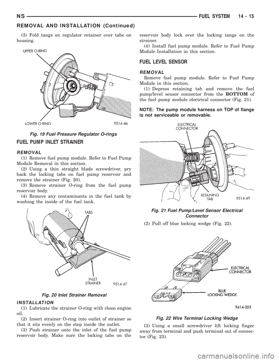
(3) Fold tangs on regulator retainer over tabs on
housing.
FUEL PUMP INLET STRAINER
REMOVAL
(1) Remove fuel pump module. Refer to Fuel Pump
Module Removal in this section.
(2) Using a thin straight blade screwdriver, pry
back the locking tabs on fuel pump reservoir and
remove the strainer (Fig. 20).
(3) Remove strainer O-ring from the fuel pump
reservoir body.
(4) Remove any contaminants in the fuel tank by
washing the inside of the fuel tank.
INSTALLATION
(1) Lubricate the strainer O-ring with clean engine
oil.
(2) Insert strainer O-ring into outlet of strainer so
that it sits evenly on the step inside the outlet.
(3) Push strainer onto the inlet of the fuel pump
reservoir body. Make sure the locking tabs on thereservoir body lock over the locking tangs on the
strainer.
(4) Install fuel pump module. Refer to Fuel Pump
Module Installation in this section.
FUEL LEVEL SENSOR
REMOVAL
Remove fuel pump module. Refer to Fuel Pump
Module in this section.
(1) Depress retaining tab and remove the fuel
pump/level sensor connector from theBOTTOMof
the fuel pump module electrical connector (Fig. 21).
NOTE: The pump module harness on TOP of flange
is not serviceable or removable.
(2) Pull off blue locking wedge (Fig. 22).
(3) Using a small screwdriver lift locking finger
away from terminal and push terminal out of connec-
tor (Fig. 23).
Fig. 19 Fuel Pressure Regulator O-rings
Fig. 20 Inlet Strainer Removal
Fig. 21 Fuel Pump/Level Sensor Electrical
Connector
Fig. 22 Wire Terminal Locking Wedge
NSFUEL SYSTEM 14 - 15
REMOVAL AND INSTALLATION (Continued)
Page 1371 of 1938
FUEL DELIVERY SYSTEMÐ2.5L DIESEL ENGINE
INDEX
page page
DESCRIPTION AND OPERATION
FUEL DRAIN TUBES..................... 7
FUEL FILTER/WATER SEPARATOR.......... 4
FUEL GAUGE SENDING UNIT.............. 4
FUEL HEATER RELAY.................... 8
FUEL HEATER.......................... 8
FUEL INJECTION PUMP.................. 5
FUEL INJECTORS....................... 6
FUEL SHUTDOWN SOLENOID............. 5
FUEL SYSTEM PRESSURE WARNING....... 3
FUEL TANK MODULE.................... 4
FUEL TANK............................ 3
FUEL TUBES/LINES/HOSES AND CLAMPSÐ
LOW-PRESSURE TYPE................. 6
HIGH-PRESSURE FUEL LINES............. 7
INTRODUCTION........................ 3
QUICK-CONNECT FITTINGSÐLOW PRESSURE
TYPE............................... 7
WASTEGATE (TURBOCHARGER)........... 8
DIAGNOSIS AND TESTING
AIR IN FUEL SYSTEM................... 11
FUEL HEATER RELAY TEST.............. 12
FUEL INJECTION PUMP TEST............. 12
FUEL INJECTOR SENSOR TEST........... 12
FUEL INJECTOR TEST.................. 12
FUEL SHUTDOWN SOLENOID TEST........ 13
FUEL SUPPLY RESTRICTIONS............ 13GENERAL INFORMATION................. 9
HIGH-PRESSURE FUEL LINE LEAK TEST.... 14
VISUAL INSPECTION..................... 9
WASTEGATE (TURBOCHARGER).......... 14
SERVICE PROCEDURES
AIR BLEED PROCEDURES............... 14
FUEL INJECTION PUMP TIMING........... 15
REMOVAL AND INSTALLATION
ACCELERATOR PEDAL.................. 16
AIR CLEANER ELEMENT................. 16
FUEL DRAIN TUBES.................... 16
FUEL FILTER/WATER SEPARATOR......... 16
FUEL HEATER RELAY................... 17
FUEL HEATER......................... 17
FUEL INJECTION PUMP................. 19
FUEL INJECTORS...................... 22
FUEL LEVEL SENSOR................... 18
FUEL RESERVOIR MODULE.............. 25
FUEL SHUTDOWN SOLENOID............ 23
FUEL TANK........................... 23
HIGH-PRESSURE LINES................. 26
SPECIFICATIONS
FUEL INJECTOR FIRING SEQUENCE....... 27
FUEL SYSTEM PRESSURE............... 27
FUEL TANK CAPACITY.................. 27
IDLE SPEED.......................... 27
DESCRIPTION AND OPERATION
INTRODUCTION
This Fuel Delivery section will cover components
not controlled by the PCM. For components con-
trolled by the PCM, refer to the Fuel Injection Sys-
temÐ2.5L Diesel Engine section of this group.
The fuel heater relay, fuel heater and fuel gauge
are not operated by the PCM. These components are
controlled by the ignition (key) switch. All other fuel
system electrical components necessary to operate
the engine are controlled or regulated by the PCM.
FUEL SYSTEM PRESSURE WARNING
WARNING: HIGH±PRESSURE FUEL LINES DELIVER
DIESEL FUEL UNDER EXTREME PRESSURE FROM
THE INJECTION PUMP TO THE FUEL INJECTORS.
THIS MAY BE AS HIGH AS 45,000 KPA (6526 PSI).
USE EXTREME CAUTION WHEN INSPECTING FORHIGH±PRESSURE FUEL LEAKS. INSPECT FOR
HIGH±PRESSURE FUEL LEAKS WITH A SHEET OF
CARDBOARD (Fig. 1). HIGH FUEL INJECTION
PRESSURE CAN CAUSE PERSONAL INJURY IF
CONTACT IS MADE WITH THE SKIN.
FUEL TANK
The fuel tank and tank mounting used with the
diesel powered engine is the same as used with gas-
oline powered models, although the fuel tank module
is different.
The fuel tank contains the fuel tank module and
two rollover valves. Two fuel lines are routed to the
fuel tank module. One line is used for fuel supply to
the fuel filter/water separator. The other is used to
return excess fuel back to the fuel tank.
The fuel tank module contains the fuel gauge elec-
trical sending unit.An electrical fuel pump is not
used with the diesel engine.
NS/GSFUEL SYSTEMÐ2.5L DIESEL ENGINE/2.0L GAS ENGINE 14 - 3
Page 1372 of 1938
FUEL TANK MODULE
An electric fuel pump is not attached to the fuel
tank module for diesel powered engines. Fuel is sup-
plied by the fuel injection pump.
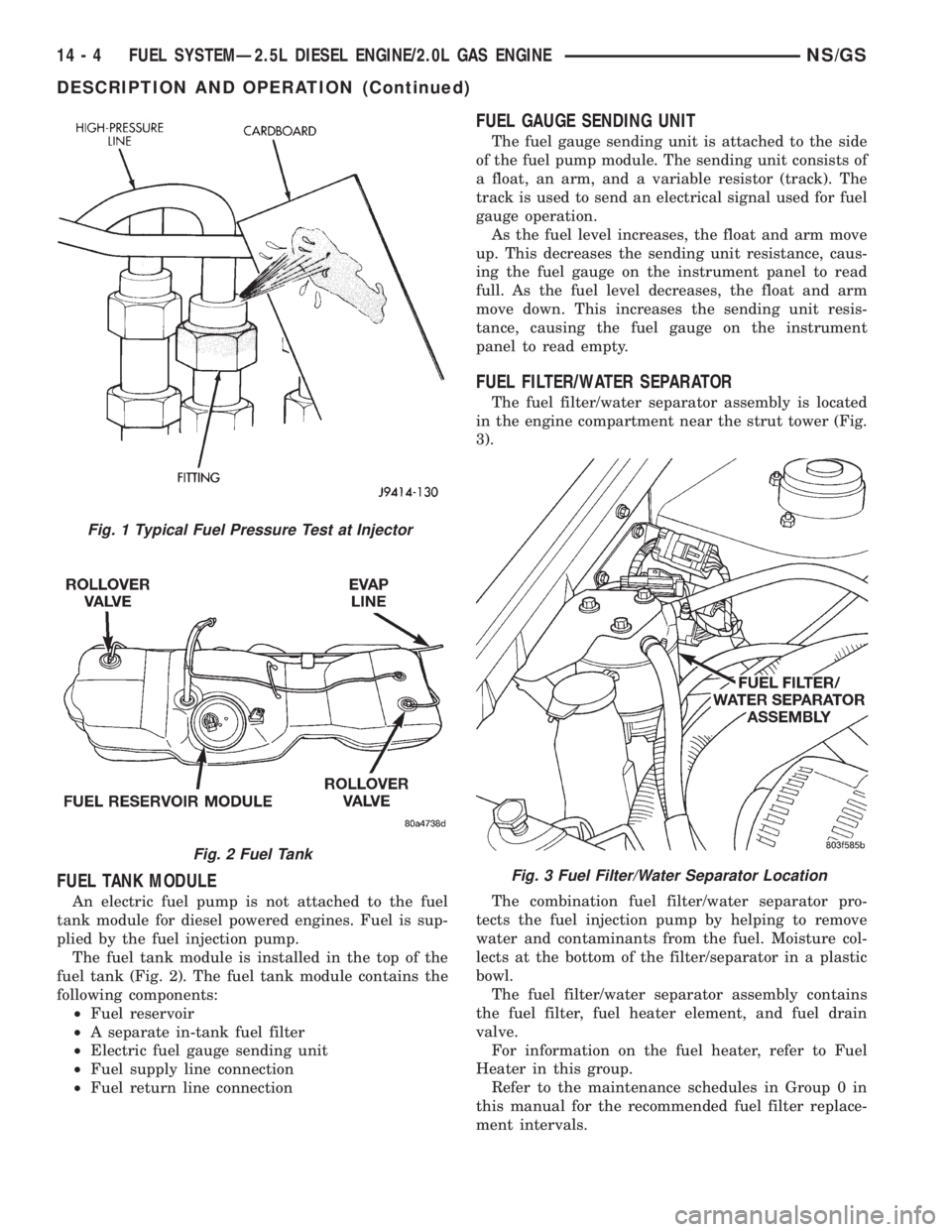
The fuel tank module is installed in the top of the
fuel tank (Fig. 2). The fuel tank module contains the
following components:
²Fuel reservoir
²A separate in-tank fuel filter
²Electric fuel gauge sending unit
²Fuel supply line connection
²Fuel return line connection
FUEL GAUGE SENDING UNIT
The fuel gauge sending unit is attached to the side
of the fuel pump module. The sending unit consists of
a float, an arm, and a variable resistor (track). The
track is used to send an electrical signal used for fuel
gauge operation.
As the fuel level increases, the float and arm move
up. This decreases the sending unit resistance, caus-
ing the fuel gauge on the instrument panel to read
full. As the fuel level decreases, the float and arm
move down. This increases the sending unit resis-
tance, causing the fuel gauge on the instrument
panel to read empty.
FUEL FILTER/WATER SEPARATOR
The fuel filter/water separator assembly is located
in the engine compartment near the strut tower (Fig.
3).
The combination fuel filter/water separator pro-
tects the fuel injection pump by helping to remove
water and contaminants from the fuel. Moisture col-
lects at the bottom of the filter/separator in a plastic
bowl.
The fuel filter/water separator assembly contains
the fuel filter, fuel heater element, and fuel drain
valve.
For information on the fuel heater, refer to Fuel
Heater in this group.
Refer to the maintenance schedules in Group 0 in
this manual for the recommended fuel filter replace-
ment intervals.
Fig. 1 Typical Fuel Pressure Test at Injector
Fig. 2 Fuel Tank
Fig. 3 Fuel Filter/Water Separator Location
14 - 4 FUEL SYSTEMÐ2.5L DIESEL ENGINE/2.0L GAS ENGINENS/GS
DESCRIPTION AND OPERATION (Continued)
Page 1386 of 1938
FUEL LEVEL SENSOR
REMOVAL
Remove fuel reservoir module. Refer to Fuel Reser-
voir Module in this section.
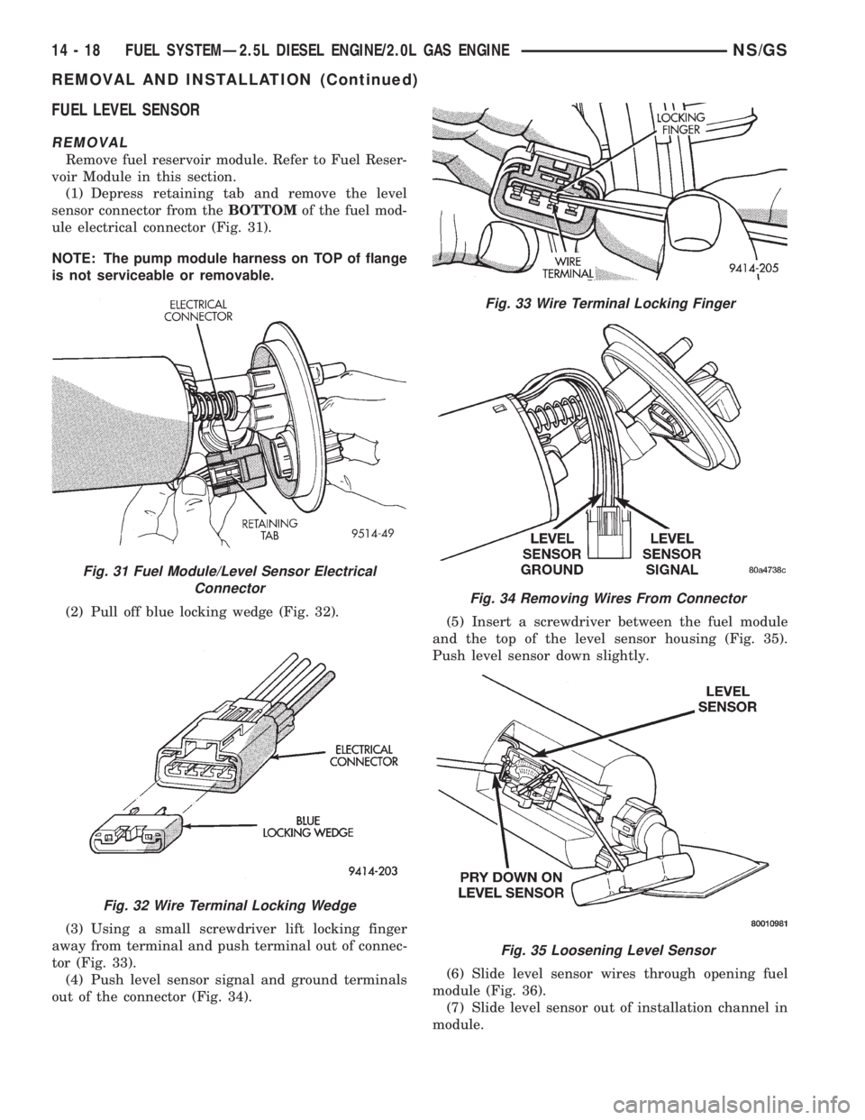
(1) Depress retaining tab and remove the level
sensor connector from theBOTTOMof the fuel mod-
ule electrical connector (Fig. 31).
NOTE: The pump module harness on TOP of flange
is not serviceable or removable.
(2) Pull off blue locking wedge (Fig. 32).
(3) Using a small screwdriver lift locking finger
away from terminal and push terminal out of connec-
tor (Fig. 33).
(4) Push level sensor signal and ground terminals
out of the connector (Fig. 34).(5) Insert a screwdriver between the fuel module
and the top of the level sensor housing (Fig. 35).
Push level sensor down slightly.
(6) Slide level sensor wires through opening fuel
module (Fig. 36).
(7) Slide level sensor out of installation channel in
module.
Fig. 31 Fuel Module/Level Sensor Electrical
Connector
Fig. 32 Wire Terminal Locking Wedge
Fig. 33 Wire Terminal Locking Finger
Fig. 34 Removing Wires From Connector
Fig. 35 Loosening Level Sensor
14 - 18 FUEL SYSTEMÐ2.5L DIESEL ENGINE/2.0L GAS ENGINENS/GS
REMOVAL AND INSTALLATION (Continued)
Page 1387 of 1938

INSTALLATION
(1) Insert level sensor wires into bottom of opening
in module.
(2) Wrap wires into groove in back of level sensor
(Fig. 37).
(3) While feeding wires into guide grooves, slide
level sensor up into channel until it snaps into place
(Fig. 38). Ensure tab at bottom of sensor locks in
place.
(4) Install level sensor wires in connector. Push
the wires up through the connector and then pull
them down until they lock in place. Ensure signal
and ground wires are installed in the correct posi-
tion.
(5) Install locking wedge on connector.
(6) Push connector up into bottom of fuel module
electrical connector.
(7) Install fuel module. Refer to Fuel Reservoir
Module in this section.FUEL INJECTION PUMP
REMOVAL
(1) Disconnect negative battery cable at battery.
(2) Thoroughly clean the area around the injection
pump and fuel lines of all dirt, grease and other con-
taminants.Due to the close internal tolerances
of the injection pump, this step must be per-
formed before removing pump.
(3) Remove the engine accessory drive belt. Refer
to Group 7, Cooling System for procedures.
(4) Remove the generator assembly.
(5) Remove the rubber fuel return and supply
hoses from metal lines at pump (Fig. 39).
(6) Remove the electrical connector at engine cool-
ant temperature sensor (Fig. 40).
(7) Disconnect the Fuel Injection Pump electrical
connector at fuel pump. (Fig. 39).
Fig. 36 Level Sensor Removal/Installation
Fig. 37 Groove in Back Side of Level Sensor
Fig. 38 Installation Channel
Fig. 39 Overflow Valve and Fuel Shutdown Solenoid
NS/GSFUEL SYSTEMÐ2.5L DIESEL ENGINE/2.0L GAS ENGINE 14 - 19
REMOVAL AND INSTALLATION (Continued)
Page 1392 of 1938
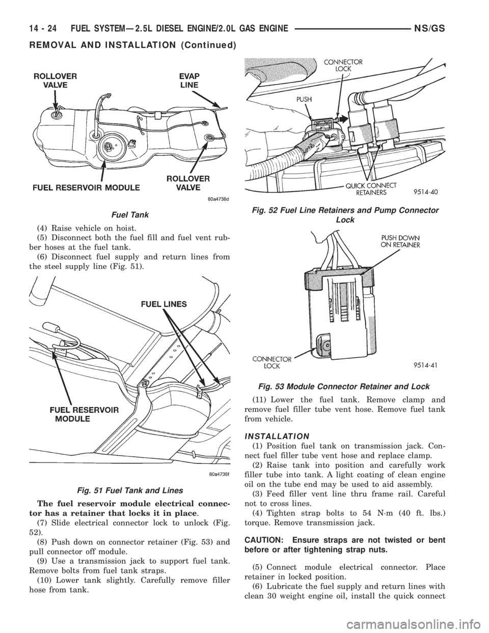
(4) Raise vehicle on hoist.
(5) Disconnect both the fuel fill and fuel vent rub-
ber hoses at the fuel tank.
(6) Disconnect fuel supply and return lines from
the steel supply line (Fig. 51).
The fuel reservoir module electrical connec-
tor has a retainer that locks it in place.
(7) Slide electrical connector lock to unlock (Fig.
52).
(8) Push down on connector retainer (Fig. 53) and
pull connector off module.
(9) Use a transmission jack to support fuel tank.
Remove bolts from fuel tank straps.
(10) Lower tank slightly. Carefully remove filler
hose from tank.(11) Lower the fuel tank. Remove clamp and
remove fuel filler tube vent hose. Remove fuel tank
from vehicle.
INSTALLATION
(1) Position fuel tank on transmission jack. Con-
nect fuel filler tube vent hose and replace clamp.
(2) Raise tank into position and carefully work
filler tube into tank. A light coating of clean engine
oil on the tube end may be used to aid assembly.
(3) Feed filler vent line thru frame rail. Careful
not to cross lines.
(4) Tighten strap bolts to 54 N´m (40 ft. lbs.)
torque. Remove transmission jack.
CAUTION: Ensure straps are not twisted or bent
before or after tightening strap nuts.
(5) Connect module electrical connector. Place
retainer in locked position.
(6) Lubricate the fuel supply and return lines with
clean 30 weight engine oil, install the quick connect
Fuel Tank
Fig. 51 Fuel Tank and Lines
Fig. 52 Fuel Line Retainers and Pump Connector
Lock
Fig. 53 Module Connector Retainer and Lock
14 - 24 FUEL SYSTEMÐ2.5L DIESEL ENGINE/2.0L GAS ENGINENS/GS
REMOVAL AND INSTALLATION (Continued)