servo CHRYSLER VOYAGER 1996 Manual PDF
[x] Cancel search | Manufacturer: CHRYSLER, Model Year: 1996, Model line: VOYAGER, Model: CHRYSLER VOYAGER 1996Pages: 1938, PDF Size: 55.84 MB
Page 1393 of 1938
fuel fitting. Refer to Tube/Fitting Assembly in the
Fuel Delivery section of this Group.
(7) Attach filler line to filler tube. Pull on connec-
tor to make sure of connection.
(8) Fill fuel tank, replace cap, and connect battery
negative cable.
FUEL RESERVOIR MODULE
REMOVAL
WARNING: THE FUEL RESERVOIR OF THE FUEL
MODULE DOES NOT EMPTY OUT WHEN THE TANK
IS DRAINED. THE FUEL IN THE RESERVOIR WILL
SPILL OUT WHEN THE MODULE IS REMOVED.
(1) Disconnect negative cable from battery.
(2) Insert fuel siphon hose into fuel filler neck and
push it into the tank.
(3) Drain fuel tank dry into holding tank or a
properly labeleddieselsafety container.
(4) Raise vehicle on hoist.
(5) Use a transmission jack to support the fuel
tank. Remove bolts from fuel tank straps. Lower
tank slightly.
(6) Clean area around fuel reservoir module and
tank to keep dirt and foreign material out of tank.
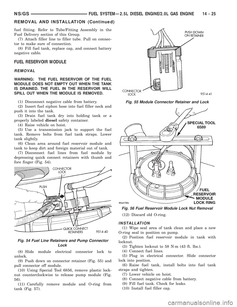
(7) Disconnect fuel lines from fuel module by
depressing quick connect retainers with thumb and
fore finger (Fig. 54).
(8) Slide module electrical connector lock to
unlock.
(9) Push down on connector retainer (Fig. 55) and
pull connector off module.
(10) Using Special Tool 6856, remove plastic lock-
nut counterclockwise to release pump module (Fig.
56).
(11) Carefully remove module and O-ring from
tank (Fig. 57).(12) Discard old O-ring.
INSTALLATION
(1) Wipe seal area of tank clean and place a new
O-ring seal in position on pump.
(2) Position fuel reservoir module in tank with
locknut.
(3) Tighten locknut to 58 N´m (43 ft. lbs.).
(4) Connect fuel lines.
(5) Plug in electrical connector. Slide connector
lock into position.
(6) Raise fuel tank, install bolts into fuel tank
straps and tighten.
(7) Lower vehicle on hoist.
(8) Connect negative cable from battery.
(9) Fill fuel tank. Check for leaks.
(10) Install fuel filler cap.
Fig. 54 Fuel Line Retainers and Pump Connector
Lock
Fig. 55 Module Connector Retainer and Lock
Fig. 56 Fuel Reservoir Module Lock Nut Removal
NS/GSFUEL SYSTEMÐ2.5L DIESEL ENGINE/2.0L GAS ENGINE 14 - 25
REMOVAL AND INSTALLATION (Continued)
Page 1394 of 1938
HIGH-PRESSURE LINES
All high±pressure fuel lines are of the same length
and inside diameter. Correct high±pressure fuel line
usage and installation is critical to smooth engine
operation.
CAUTION: The high±pressure fuel lines must be
clamped securely in place in the holders. The lines
cannot contact each other or other components. Do
not attempt to weld high±pressure fuel lines or to
repair lines that are damaged. Only use the recom-
mended lines when replacement of high±pressure
fuel line is necessary.
REMOVAL
(1) Disconnect negative battery cable from battery.
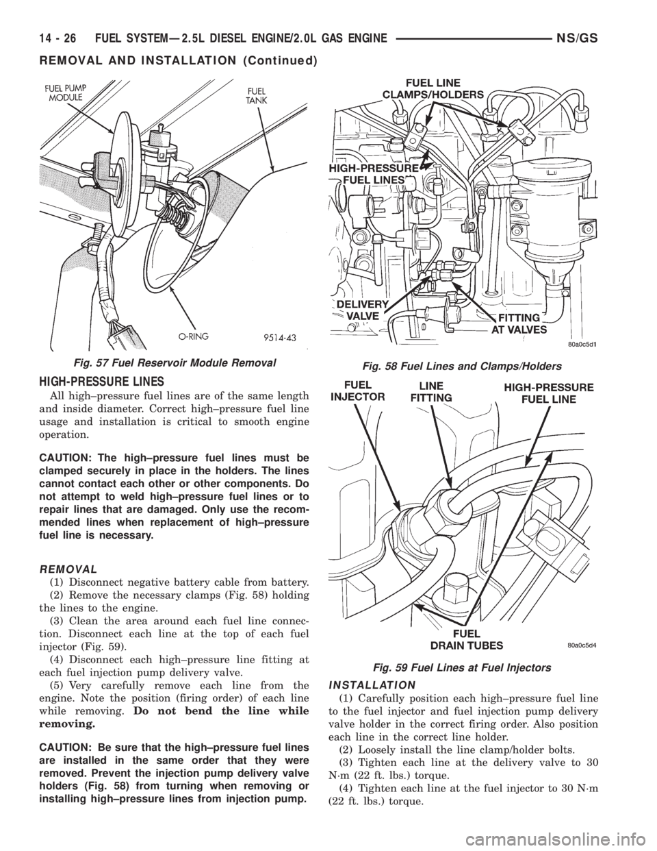
(2) Remove the necessary clamps (Fig. 58) holding
the lines to the engine.
(3) Clean the area around each fuel line connec-
tion. Disconnect each line at the top of each fuel
injector (Fig. 59).
(4) Disconnect each high±pressure line fitting at
each fuel injection pump delivery valve.
(5) Very carefully remove each line from the
engine. Note the position (firing order) of each line
while removing.Do not bend the line while
removing.
CAUTION: Be sure that the high±pressure fuel lines
are installed in the same order that they were
removed. Prevent the injection pump delivery valve
holders (Fig. 58) from turning when removing or
installing high±pressure lines from injection pump.
INSTALLATION
(1) Carefully position each high±pressure fuel line
to the fuel injector and fuel injection pump delivery
valve holder in the correct firing order. Also position
each line in the correct line holder.
(2) Loosely install the line clamp/holder bolts.
(3) Tighten each line at the delivery valve to 30
N´m (22 ft. lbs.) torque.
(4) Tighten each line at the fuel injector to 30 N´m
(22 ft. lbs.) torque.
Fig. 57 Fuel Reservoir Module RemovalFig. 58 Fuel Lines and Clamps/Holders
Fig. 59 Fuel Lines at Fuel Injectors
14 - 26 FUEL SYSTEMÐ2.5L DIESEL ENGINE/2.0L GAS ENGINENS/GS
REMOVAL AND INSTALLATION (Continued)
Page 1407 of 1938
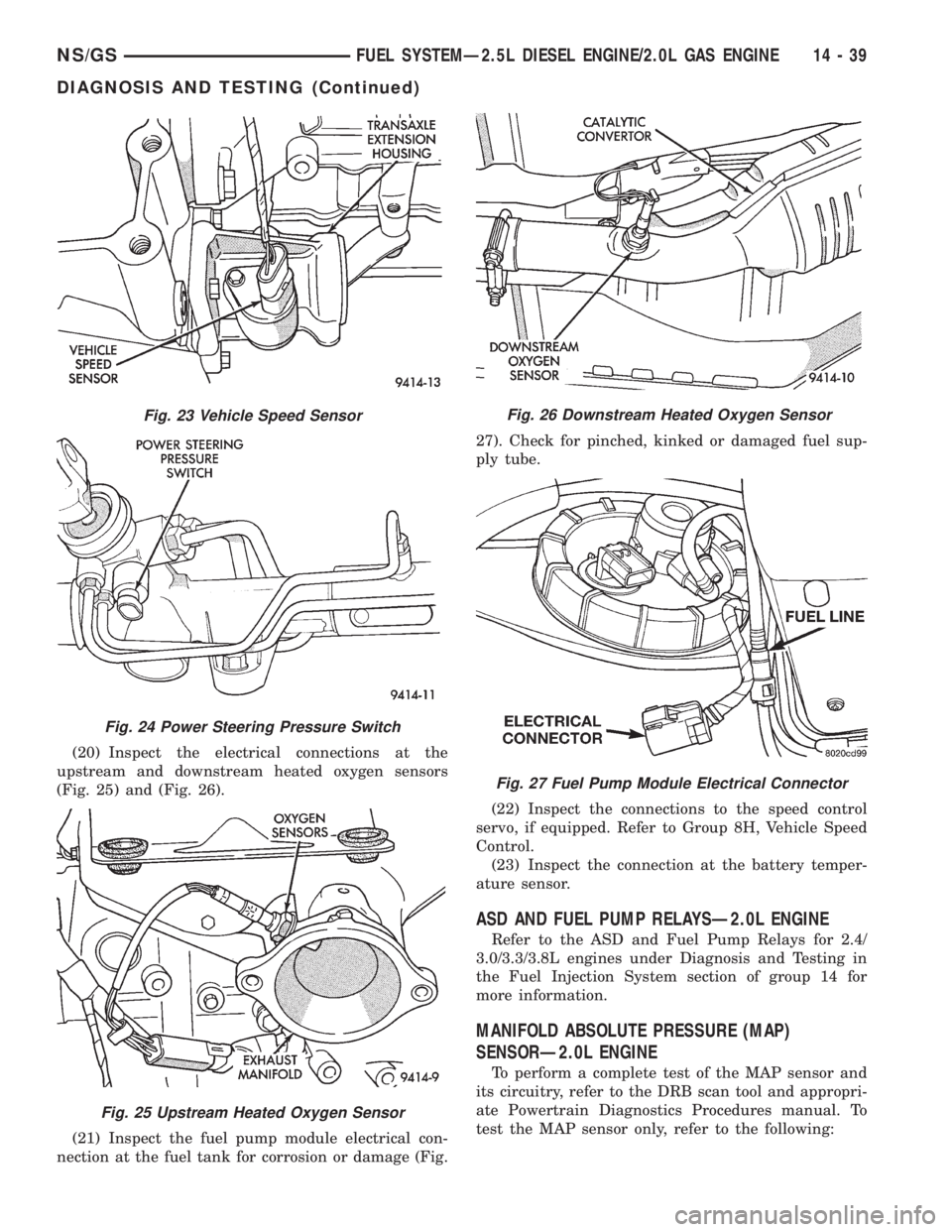
(20) Inspect the electrical connections at the
upstream and downstream heated oxygen sensors
(Fig. 25) and (Fig. 26).
(21) Inspect the fuel pump module electrical con-
nection at the fuel tank for corrosion or damage (Fig.27). Check for pinched, kinked or damaged fuel sup-
ply tube.
(22) Inspect the connections to the speed control
servo, if equipped. Refer to Group 8H, Vehicle Speed
Control.
(23) Inspect the connection at the battery temper-
ature sensor.
ASD AND FUEL PUMP RELAYSÐ2.0L ENGINE
Refer to the ASD and Fuel Pump Relays for 2.4/
3.0/3.3/3.8L engines under Diagnosis and Testing in
the Fuel Injection System section of group 14 for
more information.
MANIFOLD ABSOLUTE PRESSURE (MAP)
SENSORÐ2.0L ENGINE
To perform a complete test of the MAP sensor and
its circuitry, refer to the DRB scan tool and appropri-
ate Powertrain Diagnostics Procedures manual. To
test the MAP sensor only, refer to the following:
Fig. 23 Vehicle Speed Sensor
Fig. 24 Power Steering Pressure Switch
Fig. 25 Upstream Heated Oxygen Sensor
Fig. 26 Downstream Heated Oxygen Sensor
Fig. 27 Fuel Pump Module Electrical Connector
NS/GSFUEL SYSTEMÐ2.5L DIESEL ENGINE/2.0L GAS ENGINE 14 - 39
DIAGNOSIS AND TESTING (Continued)
Page 1429 of 1938
CONDITION POSSIBLE CAUSES CORRECTION
Power steering pump growl results from the development of high pressure fluid flow. Normally this noise
should not be high enough to be objectionable. Abnormal situations, such as a low oil level causing
aeration or hose touching the vehicle body, can create a noise level that could bring complaints.
WHINE OR GROWL (PUMP
NOISE)1. Low fluid level. 1. Fill power steering fluid
reservoir to proper level and
perform leakage diagnosis.
(Recheck fluid level after power
steering fluid is free of air.)
2. Power steering hose touching
vehicle body or frame.2. Reposition power steering
hose. Replace hose if tube ends
are bent.
3. Extreme wear of power
steering pump internal parts.3. Replace power steering pump
and flush system.
SUCKING AIR SOUND 1. Loose clamp on power steering
fluid low pressure hose.1. Tighten or replace hose clamp.
2. Missing O-Ring on power
steering pressure hose
connection.2. Inspect connection and replace
O-Ring as required.
3. Low power steering fluid level 3. Fill power steering fluid
reservoir to proper level and
perform leakage diagnosis.
4. Air leak between power
steering fluid reservoir and power
steering pump.4. Inspect and/or replace power
steering fluid reservoir or supply
hose as required.
SQUEAK OR RUBBING
SOUND1. Sound coming from steering
column.1.Check for squeak in steering
column. Inspect for contact
between shroud, intermediate
shaft, column, and steering wheel.
Realign if necessary.Note: Check
steering column for noise
without clockspriing installed
and with the steering column
shaft removed from the steering
intermediate shaft. This must be
done before removing the
steering column for a noise
complaint.
2. Check for lack or grease on
steering column dash panel to
lower coupler seal.
2.Clockspring 3. Replace Clockspring
3. Sound internal to steering gear. 4. Replace steering gear
assembly.
SCRUBBING OR KNOCKING
SOUND1. Incorrect tire size. 1. Verify that tire size on vehicle is
the same as originally supplied.
2. Check clearance between tires
and other vehicle components,
through the full travel of the
suspension.2. Correct as necessary.
3. Check for interference between
steering gear and other
components.3.Correct as necessary.
4.Incorrect steering gear supplied. 4. Replace steering gear with
correct steering gear for specific
vehicle.
NSSTEERING 19 - 3
DIAGNOSIS AND TESTING (Continued)
Page 1430 of 1938
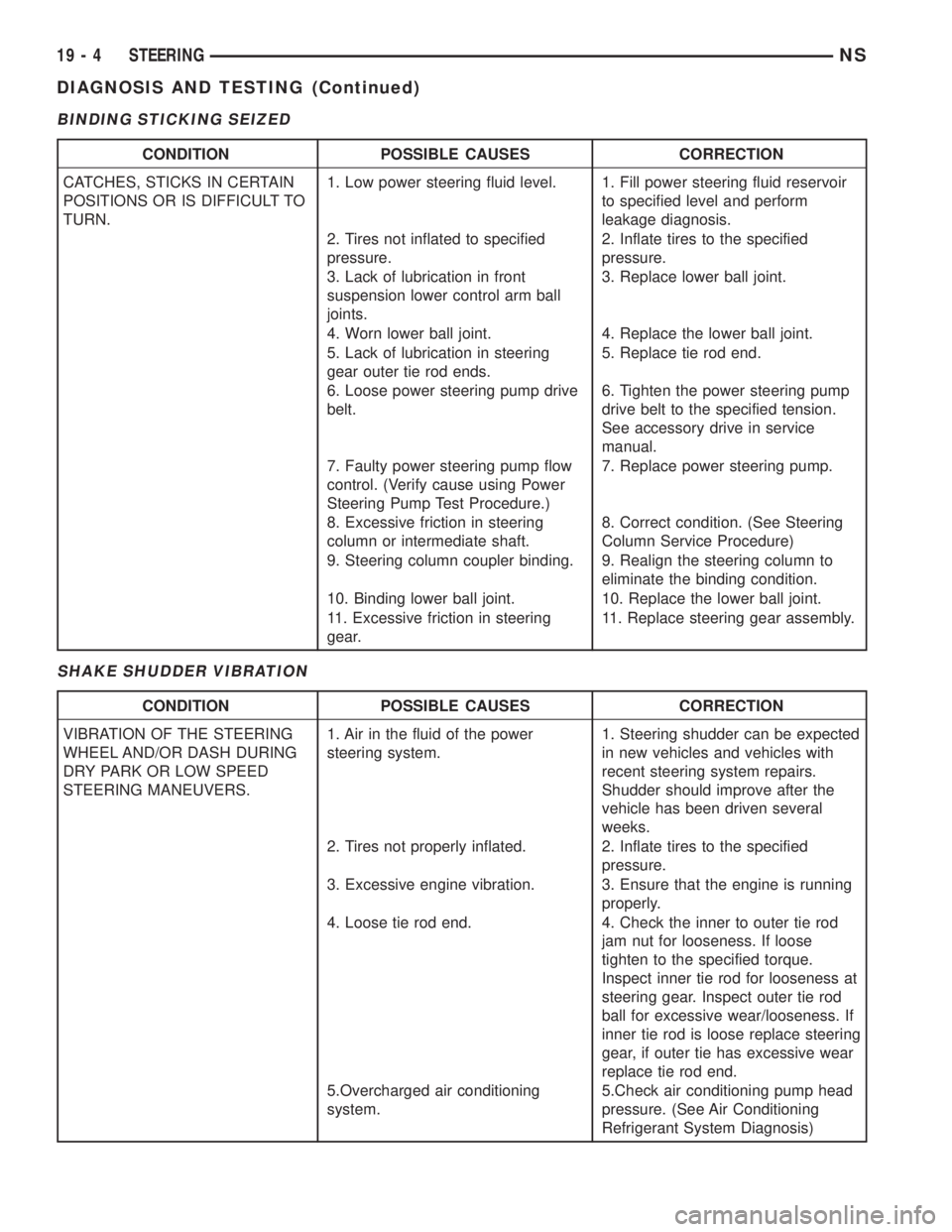
BINDING STICKING SEIZED
SHAKE SHUDDER VIBRATION
CONDITION POSSIBLE CAUSES CORRECTION
CATCHES, STICKS IN CERTAIN
POSITIONS OR IS DIFFICULT TO
TURN.1. Low power steering fluid level. 1. Fill power steering fluid reservoir
to specified level and perform
leakage diagnosis.
2. Tires not inflated to specified
pressure.2. Inflate tires to the specified
pressure.
3. Lack of lubrication in front
suspension lower control arm ball
joints.3. Replace lower ball joint.
4. Worn lower ball joint. 4. Replace the lower ball joint.
5. Lack of lubrication in steering
gear outer tie rod ends.5. Replace tie rod end.
6. Loose power steering pump drive
belt.6. Tighten the power steering pump
drive belt to the specified tension.
See accessory drive in service
manual.
7. Faulty power steering pump flow
control. (Verify cause using Power
Steering Pump Test Procedure.)7. Replace power steering pump.
8. Excessive friction in steering
column or intermediate shaft.8. Correct condition. (See Steering
Column Service Procedure)
9. Steering column coupler binding. 9. Realign the steering column to
eliminate the binding condition.
10. Binding lower ball joint. 10. Replace the lower ball joint.
11. Excessive friction in steering
gear.11. Replace steering gear assembly.
CONDITION POSSIBLE CAUSES CORRECTION
VIBRATION OF THE STEERING
WHEEL AND/OR DASH DURING
DRY PARK OR LOW SPEED
STEERING MANEUVERS.1. Air in the fluid of the power
steering system.1. Steering shudder can be expected
in new vehicles and vehicles with
recent steering system repairs.
Shudder should improve after the
vehicle has been driven several
weeks.
2. Tires not properly inflated. 2. Inflate tires to the specified
pressure.
3. Excessive engine vibration. 3. Ensure that the engine is running
properly.
4. Loose tie rod end. 4. Check the inner to outer tie rod
jam nut for looseness. If loose
tighten to the specified torque.
Inspect inner tie rod for looseness at
steering gear. Inspect outer tie rod
ball for excessive wear/looseness. If
inner tie rod is loose replace steering
gear, if outer tie has excessive wear
replace tie rod end.
5.Overcharged air conditioning
system.5.Check air conditioning pump head
pressure. (See Air Conditioning
Refrigerant System Diagnosis)
19 - 4 STEERINGNS
DIAGNOSIS AND TESTING (Continued)
Page 1431 of 1938
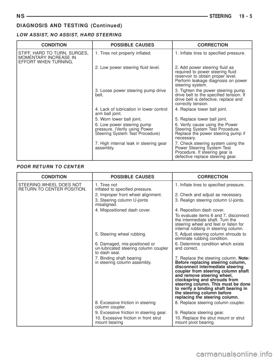
LOW ASSIST, NO ASSIST, HARD STEERING
POOR RETURN TO CENTER
CONDITION POSSIBLE CAUSES CORRECTION
STIFF, HARD TO TURN, SURGES,
MOMENTARY INCREASE IN
EFFORT WHEN TURNING.1. Tires not properly inflated. 1. Inflate tires to specified pressure.
2. Low power steering fluid level. 2. Add power steering fluid as
required to power steering fluid
reservoir to obtain proper level.
Perform leakage diagnosis on power
steering system.
3. Loose power steering pump drive
belt.3. Tighten the power steering pump
drive belt to the specified tension. If
drive belt is defective, replace and
correctly tension.
4. Lack of lubrication in lower control
arm ball joint.4. Replace lower ball joint.
5. Worn lower ball joint. 5. Replace lower ball joint.
6. Low power steering pump
pressure. (Verify using Power
Steering System Test Procedure)6. Verify cause using the Power
Steering System Test Procedure.
Replace the power steering pump if
necessary.
7. High internal leak in steering gear
assembly.7. Check steering system using the
Power Steering System Test
Procedure. If steering gear is
defective replace steering gear.
CONDITION POSSIBLE CAUSES CORRECTION
STEERING WHEEL DOES NOT
RETURN TO CENTER POSITION.1. Tires not
inflated to specified pressure.1. Inflate tires to specified pressure.
2. Improper front wheel alignment. 2. Check and adjust as necessary.
3. Steering column U-joints
misaligned.3. Realign steering column U-joints.
4. Mispositioned dash cover. 4. Reposition dash cover.
To evaluate items 6 and 7, disconnect
the intermediate shaft. Turn the
steering wheel and feel or listen for
internal rubbing in steering column.
5. Steering wheel rubbing. 5. Adjust steering column shrouds to
eliminate rubbing condition.
6. Damaged, mis-positioned or
un-lubricated steering column coupler
to dash seal.6. Determine condition which exists
and correct.
7. Binding shaft bearing
in steering column assembly.7. Replace the steering column.Note:
Before replacing steering column,
disconnect intermediate steering
coupler from steering column shaft
and remove steering wheel,
clockspring and shrouds from
steering column. This must be done
to verify a binding shaft bearing in
the steering column before
replacing the steering column.
8. Excessive friction in steering
column coupler.8. Replace steering column coupler.
9. Excessive friction in steering gear. 9. Replace steering gear.
10. Excessive friction in front strut
mount bearing10. Replace the strut mount or strut
mount pivot bearing.
NSSTEERING 19 - 5
DIAGNOSIS AND TESTING (Continued)
Page 1432 of 1938
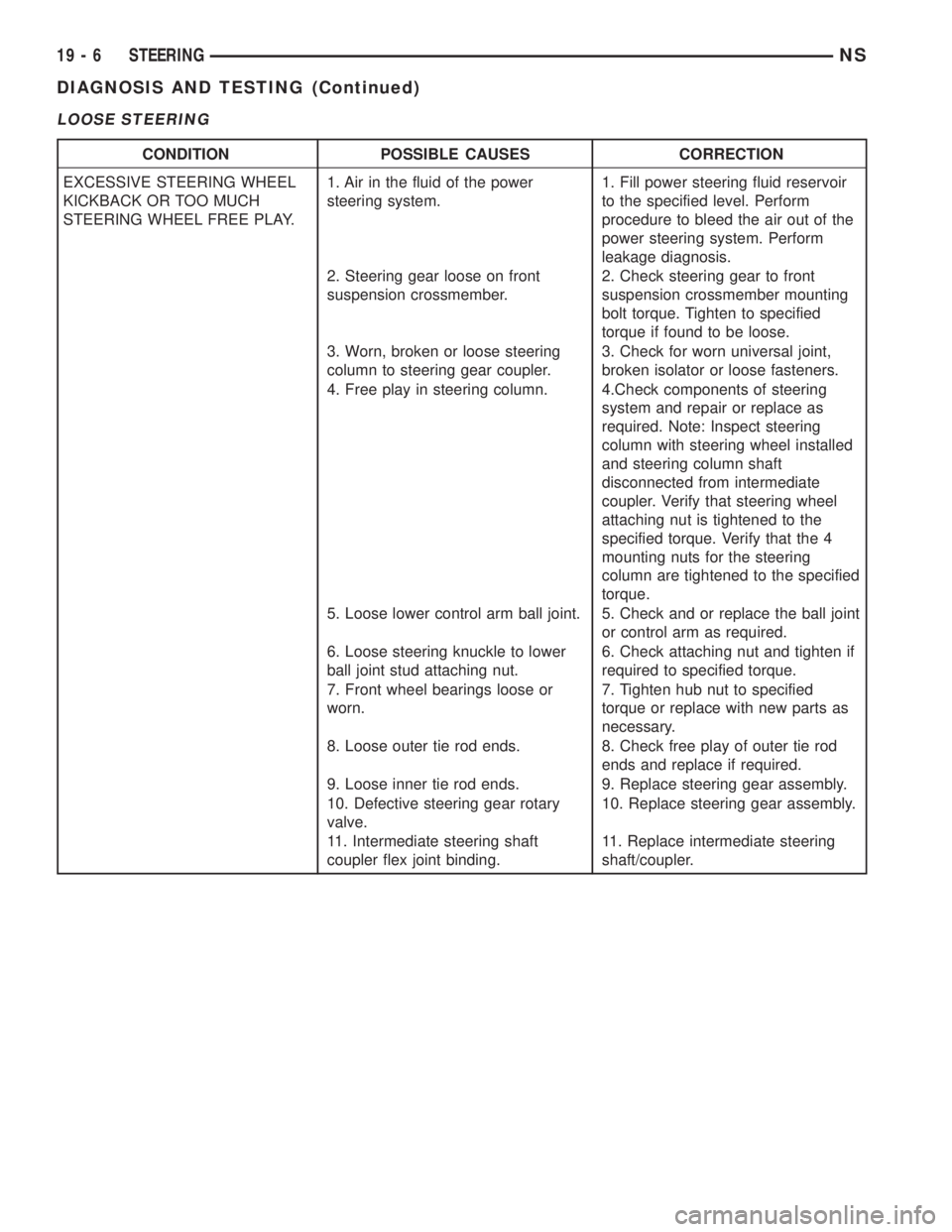
LOOSE STEERING
CONDITION POSSIBLE CAUSES CORRECTION
EXCESSIVE STEERING WHEEL
KICKBACK OR TOO MUCH
STEERING WHEEL FREE PLAY.1. Air in the fluid of the power
steering system.1. Fill power steering fluid reservoir
to the specified level. Perform
procedure to bleed the air out of the
power steering system. Perform
leakage diagnosis.
2. Steering gear loose on front
suspension crossmember.2. Check steering gear to front
suspension crossmember mounting
bolt torque. Tighten to specified
torque if found to be loose.
3. Worn, broken or loose steering
column to steering gear coupler.3. Check for worn universal joint,
broken isolator or loose fasteners.
4. Free play in steering column. 4.Check components of steering
system and repair or replace as
required. Note: Inspect steering
column with steering wheel installed
and steering column shaft
disconnected from intermediate
coupler. Verify that steering wheel
attaching nut is tightened to the
specified torque. Verify that the 4
mounting nuts for the steering
column are tightened to the specified
torque.
5. Loose lower control arm ball joint. 5. Check and or replace the ball joint
or control arm as required.
6. Loose steering knuckle to lower
ball joint stud attaching nut.6. Check attaching nut and tighten if
required to specified torque.
7. Front wheel bearings loose or
worn.7. Tighten hub nut to specified
torque or replace with new parts as
necessary.
8. Loose outer tie rod ends. 8. Check free play of outer tie rod
ends and replace if required.
9. Loose inner tie rod ends. 9. Replace steering gear assembly.
10. Defective steering gear rotary
valve.10. Replace steering gear assembly.
11. Intermediate steering shaft
coupler flex joint binding.11. Replace intermediate steering
shaft/coupler.
19 - 6 STEERINGNS
DIAGNOSIS AND TESTING (Continued)
Page 1433 of 1938
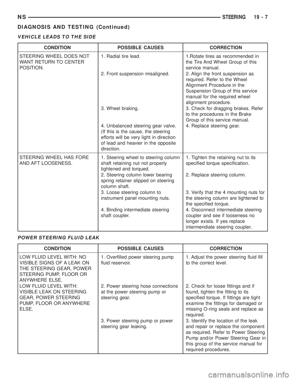
VEHICLE LEADS TO THE SIDE
POWER STEERING FLUID LEAK
CONDITION POSSIBLE CAUSES CORRECTION
STEERING WHEEL DOES NOT
WANT RETURN TO CENTER
POSITION.1. Radial tire lead. 1.Rotate tires as recommended in
the Tire And Wheel Group of this
service manual.
2. Front suspension misaligned. 2. Align the front suspension as
required. Refer to the Wheel
Alignment Procedure in the
Suspension Group of this service
manual for the required wheel
alignment procedure.
3. Wheel braking. 3. Check for dragging brakes. Refer
to the procedures in the Brake
Group of this service manual.
4. Unbalanced steering gear valve.
(If this is the cause, the steering
efforts will be very light in direction
of lead and heavier in the opposite
direction.4. Replace steering gear.
STEERING WHEEL HAS FORE
AND AFT LOOSENESS.1. Steering wheel to steering column
shaft retaining nut not properly
tightened and torqued.1. Tighten the retaining nut to its
specified torque specification.
2. Steering column lower bearing
spring retainer slipped on steering
column shaft.2. Replace steering column.
3. Loose steering column to
instrument panel mounting nuts.3. Verify that the 4 mounting nuts for
the steering column are tightened to
the specified torque.
4. Binding intermediate steering
shaft coupler.4. Disconnect intermediate steering
coupler and see if looseness no
longer exists. If yes replace
intermendiate steering coupler.
CONDITION POSSIBLE CAUSES CORRECTION
LOW FLUID LEVEL WITH: NO
VISIBLE SIGNS OF A LEAK ON
THE STEERING GEAR, POWER
STEERING PUMP, FLOOR OR
ANYWHERE ELSE.1. Overfilled power steering pump
fluid reservoir.1. Adjust the power steering fluid fill
to the correct level.
LOW FLUID LEVEL WITH:
VISIBLE LEAK ON STEERING
GEAR, POWER STEERING
PUMP, FLOOR OR ANYWHERE
ELSE.2. Power steering hose connections
at the power steering pump or
steering gear.2. Check for loose fittings and if
found, tighten the fitting to its
specified torque. If fittings are tight
examine the fittings for damaged or
missing O-ring seals and replace as
required.
3. Power steering pump or power
steering gear leaking.3. Identify the location of the leak
and repair or replace the component
as required. Refer to Power Steering
Pump and/or Power Steering Gear in
this group of the service manual for
required procedures.
NSSTEERING 19 - 7
DIAGNOSIS AND TESTING (Continued)
Page 1435 of 1938
POWER STEERING PUMP
INDEX
page page
DESCRIPTION AND OPERATION
POWER STEERING PUMP OPERATION....... 9
DIAGNOSIS AND TESTING
POWER STEERING PUMP FLOW RATE AND
PRESSURE TEST....................... 9
SERVICE PROCEDURES
POWER STEERING PUMP INITIAL
OPERATION.......................... 10
POWER STEERING SYSTEM FLUID LEVEL
CHECK.............................. 10
REMOVAL AND INSTALLATION
2.4 LITER POWER STEERING PUMP......... 11
3.0 LITER POWER STEERING PUMP........ 13
3.3/3.8 LITER POWER STEERING PUMP...... 16
POWER STEERING FLUID PRESSURE HOSE . . 19POWER STEERING FLUID RESERVOIR TO
PUMP SUPPLY HOSE................... 18
POWER STEERING FLUID RETURN HOSE.... 21
REMOTE POWER STEERING FLUID
RESERVOIR.......................... 22
DISASSEMBLY AND ASSEMBLY
POWER STEERING PUMP FLOW CONTROL
VALVE SEAL.......................... 23
POWER STEERING PUMP PULLEY.......... 23
SPECIFICATIONS
POWER STEERING PUMP FASTENER
TORQUE SPECIFICATIONS.............. 24
POWER STEERING SYSTEM
SPECIFICATIONS...................... 24
SPECIAL TOOLS
POWER STEERING PUMP................. 25
DESCRIPTION AND OPERATION
POWER STEERING PUMP OPERATION
Hydraulic pressure for the operation of the power
steering gear is provided by a belt driven power
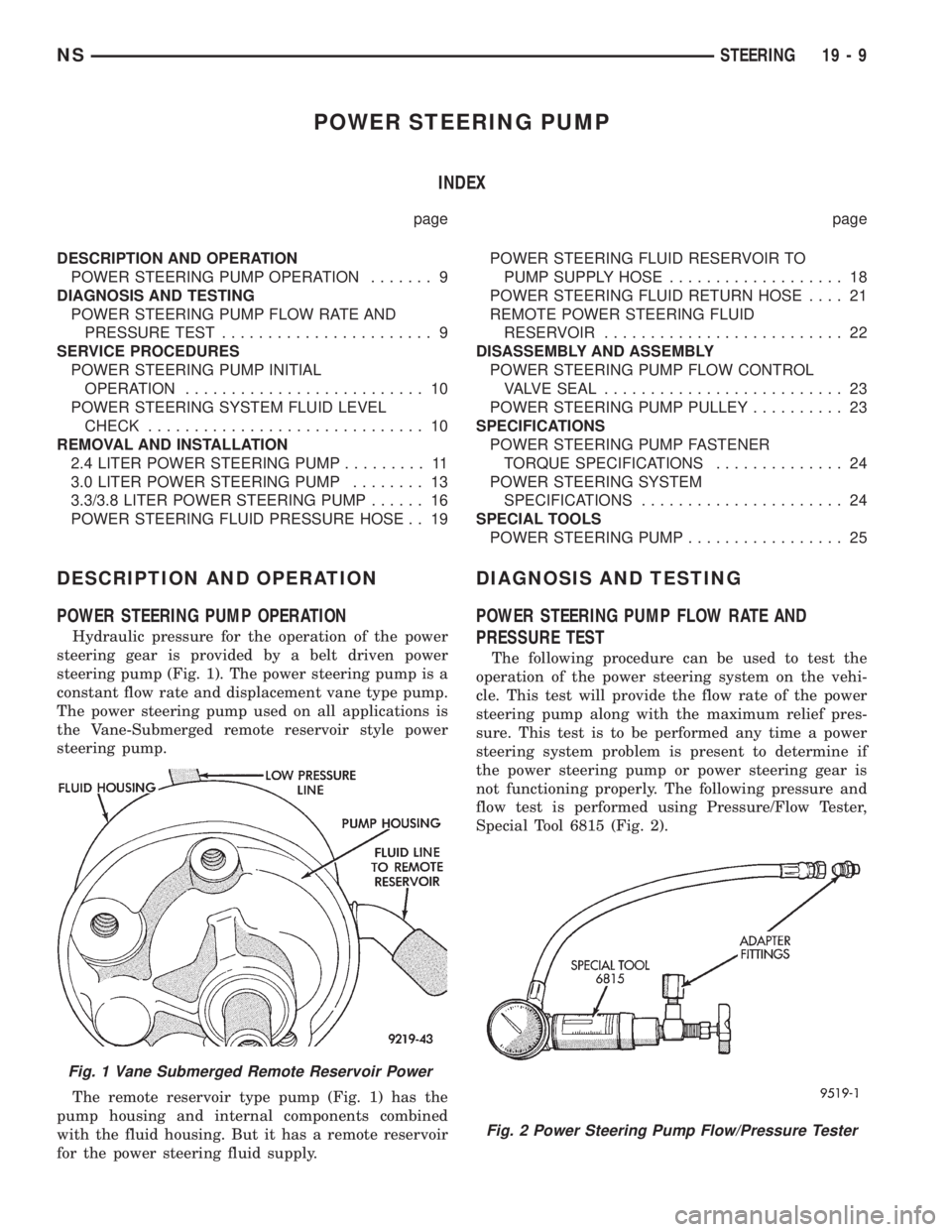
steering pump (Fig. 1). The power steering pump is a
constant flow rate and displacement vane type pump.
The power steering pump used on all applications is
the Vane-Submerged remote reservoir style power
steering pump.
The remote reservoir type pump (Fig. 1) has the
pump housing and internal components combined
with the fluid housing. But it has a remote reservoir
for the power steering fluid supply.
DIAGNOSIS AND TESTING
POWER STEERING PUMP FLOW RATE AND
PRESSURE TEST
The following procedure can be used to test the
operation of the power steering system on the vehi-
cle. This test will provide the flow rate of the power
steering pump along with the maximum relief pres-
sure. This test is to be performed any time a power
steering system problem is present to determine if
the power steering pump or power steering gear is
not functioning properly. The following pressure and
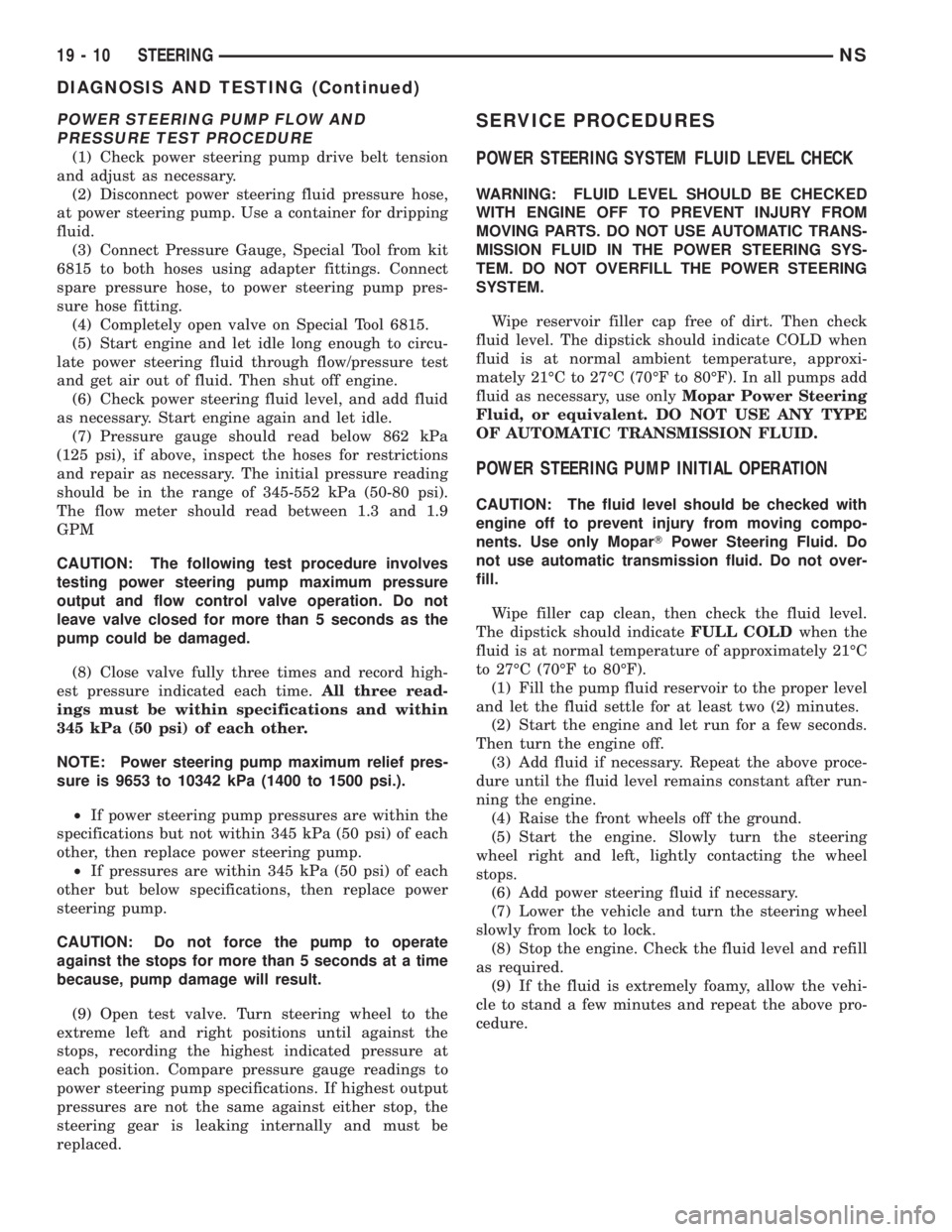
flow test is performed using Pressure/Flow Tester,
Special Tool 6815 (Fig. 2).
Fig. 1 Vane Submerged Remote Reservoir Power
Fig. 2 Power Steering Pump Flow/Pressure Tester
NSSTEERING 19 - 9
Page 1436 of 1938
POWER STEERING PUMP FLOW AND
PRESSURE TEST PROCEDURE
(1) Check power steering pump drive belt tension
and adjust as necessary.
(2) Disconnect power steering fluid pressure hose,
at power steering pump. Use a container for dripping
fluid.
(3) Connect Pressure Gauge, Special Tool from kit
6815 to both hoses using adapter fittings. Connect
spare pressure hose, to power steering pump pres-
sure hose fitting.
(4) Completely open valve on Special Tool 6815.
(5) Start engine and let idle long enough to circu-
late power steering fluid through flow/pressure test
and get air out of fluid. Then shut off engine.
(6) Check power steering fluid level, and add fluid
as necessary. Start engine again and let idle.
(7) Pressure gauge should read below 862 kPa
(125 psi), if above, inspect the hoses for restrictions
and repair as necessary. The initial pressure reading
should be in the range of 345-552 kPa (50-80 psi).
The flow meter should read between 1.3 and 1.9
GPM
CAUTION: The following test procedure involves
testing power steering pump maximum pressure
output and flow control valve operation. Do not
leave valve closed for more than 5 seconds as the
pump could be damaged.
(8) Close valve fully three times and record high-
est pressure indicated each time.All three read-
ings must be within specifications and within
345 kPa (50 psi) of each other.
NOTE: Power steering pump maximum relief pres-
sure is 9653 to 10342 kPa (1400 to 1500 psi.).
²If power steering pump pressures are within the
specifications but not within 345 kPa (50 psi) of each
other, then replace power steering pump.
²If pressures are within 345 kPa (50 psi) of each
other but below specifications, then replace power
steering pump.
CAUTION: Do not force the pump to operate
against the stops for more than 5 seconds at a time
because, pump damage will result.
(9) Open test valve. Turn steering wheel to the
extreme left and right positions until against the
stops, recording the highest indicated pressure at
each position. Compare pressure gauge readings to
power steering pump specifications. If highest output
pressures are not the same against either stop, the
steering gear is leaking internally and must be
replaced.
SERVICE PROCEDURES
POWER STEERING SYSTEM FLUID LEVEL CHECK
WARNING: FLUID LEVEL SHOULD BE CHECKED
WITH ENGINE OFF TO PREVENT INJURY FROM
MOVING PARTS. DO NOT USE AUTOMATIC TRANS-
MISSION FLUID IN THE POWER STEERING SYS-
TEM. DO NOT OVERFILL THE POWER STEERING
SYSTEM.
Wipe reservoir filler cap free of dirt. Then check
fluid level. The dipstick should indicate COLD when
fluid is at normal ambient temperature, approxi-
mately 21ÉC to 27ÉC (70ÉF to 80ÉF). In all pumps add
fluid as necessary, use onlyMopar Power Steering
Fluid, or equivalent. DO NOT USE ANY TYPE
OF AUTOMATIC TRANSMISSION FLUID.
POWER STEERING PUMP INITIAL OPERATION
CAUTION: The fluid level should be checked with
engine off to prevent injury from moving compo-
nents. Use only MoparTPower Steering Fluid. Do
not use automatic transmission fluid. Do not over-
fill.
Wipe filler cap clean, then check the fluid level.
The dipstick should indicateFULL COLDwhen the
fluid is at normal temperature of approximately 21ÉC
to 27ÉC (70ÉF to 80ÉF).
(1) Fill the pump fluid reservoir to the proper level
and let the fluid settle for at least two (2) minutes.
(2) Start the engine and let run for a few seconds.
Then turn the engine off.
(3) Add fluid if necessary. Repeat the above proce-
dure until the fluid level remains constant after run-
ning the engine.
(4) Raise the front wheels off the ground.
(5) Start the engine. Slowly turn the steering
wheel right and left, lightly contacting the wheel
stops.
(6) Add power steering fluid if necessary.
(7) Lower the vehicle and turn the steering wheel
slowly from lock to lock.
(8) Stop the engine. Check the fluid level and refill
as required.
(9) If the fluid is extremely foamy, allow the vehi-
cle to stand a few minutes and repeat the above pro-
cedure.
19 - 10 STEERINGNS
DIAGNOSIS AND TESTING (Continued)