engine CHRYSLER VOYAGER 2001 Service Manual
[x] Cancel search | Manufacturer: CHRYSLER, Model Year: 2001, Model line: VOYAGER, Model: CHRYSLER VOYAGER 2001Pages: 4284, PDF Size: 83.53 MB
Page 4072 of 4284
POWERTRAIN VERIFICATION TEST VER - 4 APPLICABILITY
1. NOTE: If the PCM has been replaced and the correct VIN and mileage have not
been programmed, a DTC will be set in the ABS Module, Airbag Module and the
SKIM.
2. NOTE: If the vehicle is equipped with a Sentry Key Immobilizer System, Secret
Key data must be updated. Refer to the Service Information for the PCM, SKIM and
the Transponder (ignition key) for programming information.
3. Inspect the vehicle to ensure that all engine components are properly installed and
connected.
4. Connect the DRB to the data link connector and erase all codes.
5. Turn the speed control ON (if equipped, cruise light will be on).
6. Depress and release the SET Switch. If the speed control did not engage, the repair is not
complete. Check for TSBs that pertain to speed control problem and then, if necessary, return
to Symptom List.
7. Depress and hold the RESUME/ACCEL Switch. If the vehicle speed did not increase by at
least 2 mph, the repair is not complete. Check for TSBs that pertain to speed control problem
and then, if necessary, return to Symptom List.
8. Press and hold the COAST switch. The vehicle speed should decrease. If it did not decrease,
the repair is not complete. Check for TSBs that pertain to speed control problem and then, if
necessary, return to Symptom List.
9. Using caution, depress and release the brake pedal. If the speed control did not disengage,
the repair is not complete. Check for TSBs that pertain to speed control problem and then, if
necessary, return to Symptom List.
10. Bring the vehicle speed back up to 35 MPH.
11. Depress the RESUME/ACCEL switch. If the speed control did not resume the previously set
speed, the repair is not complete. Check for TSBs that pertain to speed control problem and
then, if necessary, return to Symptom List.
12. Hold down the SET switch. If the vehicle did not decelerate, the repair is not complete.
Check for TSBs that pertain to speed control problem and then, if necessary, return to
Symptom List.
13. Ensure vehicle speed is greater than 35 mph and release the SET Switch. If vehicle did not
adjust and set a new vehicle speed, the repair is not complete. Check for TSBs that pertain to
speed control problem and then, if necessary, return to Symptom List.
14. Depress and release the CANCEL switch. If the speed control did not disengage, the repair
is not complete. Check for TSBs that pertain to speed control problem and then, if necessary,
return to Symptom List.
15. Bring the vehicle speed back up above 35 mph and engage speed control.
16. Depress the OFF switch to turn OFF, (Cruise light will be off). If the speed control did not
disengage, the repair is not complete. Check for TSBs that pertain to speed control problem and
then, if necessary, return to Symptom List.
17. If the vehicle successfully passed all of the previous tests, the speed control system is now
functioning as designed. The repair is now complete.
Did the Speed Control pass the above test?All
Ye s®Repair is complete.
No®Repair is not complete, refer to appropriate symptom.
278
VERIFICATION TESTS
VERIFICATION TESTS ÐContinued
Page 4073 of 4284
POWERTRAIN VERIFICATION TEST VER - 5 APPLICABILITY
1. NOTE: If the PCM has been replaced and the correct VIN and mileage have not
been programmed, a DTC will be set in the ABS Module, Airbag Module and the
SKIM.
2. NOTE: If the vehicle is equipped with a Sentry Key Immobilizer System, Secret
Key data must be updated. Refer to the Service Information for the PCM, SKIM and
the Transponder (ignition key) for programming information.
3. Inspect the vehicle to ensure that all engine components are properly installed and
connected. Reassemble and reconnect components as necessary.
4. Connect the DRBIIItto the data link connector.
5. Ensure the fuel tank has at least a quarter tank of fuel. Turn off all accessories.
6. If a Comprehensive Component DTC was repaired, perform steps5-8.IfaMajor OBDII
Monitor DTC was repaired skip those steps and continue verification.
7. After the ignition has been off for at least 10 seconds, restart the vehicle and run 2 minutes.
8. If the Good Trip counter changed to one or more and there are no new DTC's, the repair was
successful and is now complete. Erase DTC's and disconnect the DRBIIIt.
9. If the repaired DTC has reset, the repair is not complete. Check for any related TSB's or flash
updates and return to the Symptom list.
10. If another DTC has set, return to the Symptom List and follow the path specified for that
DTC.
11. With the DRBIIIt, monitor the appropriate pre-test enabling conditions until all conditions
have been met. Once the conditions have been met, switch screen to the appropriate OBDII
monitor, (Audible beeps when the monitor is running).
12. If the monitor ran, and the Good Trip counter changed to one or more, the repair was
successful and is now complete. Erase DTC's and disconnect the DRBIIIt.
13. If the repaired OBDII trouble code has reset or was seen in the monitor while on the road
test, the repair is not complete. Check for any related technical service bulletins or flash
updates and return to Symptom List.
14. If another DTC has set, return to the Symptom List and follow the path specified for that
DTC.
Are any DTCs present?All
Ye s®Repair is not complete, refer to appropriate symptom.
No®Repair is complete.
279
VERIFICATION TESTS
VERIFICATION TESTS ÐContinued
Page 4074 of 4284
POWERTRAIN VERIFICATION TEST VER - 6 APPLICABILITY
1. NOTE: If the PCM has been replaced and the correct VIN and mileage have not
been programmed, a DTC will be set in the ABS Module, Airbag Module and the
SKIM.
2. NOTE: If the vehicle is equipped with a Sentry Key Immobilizer System, Secret
Key data must be updated. Refer to the Service Information for the PCM, SKIM and
the Transponder (ignition key) for programming information.
3. Inspect the vehicle to ensure that all engine components are properly installed and
connected. Reassemble and reconnect components as necessary.
4. The LDP Monitor Test Mode has been added to the DRBIII to verify repairs to the LDP
System. A DRB software program was written which causes the PCM to run the LDP Monitor
as part of this test. Test failures will be indicated through a stored DTC.
5. LDP Monitor Test Mode is a useful way to run a total system performance test. Use this test
to verify any type of LDP system repair.
6. Software program makes temporary changes to operating mode of PCM. For this reason, it
is critical that test not be interrupted. PCM's left in this mode as result of interrupted test will
illuminate the MIL for 8-10 mi of driving with no DTC's stored.
7. Erasing DTC's will not change this condition.
8. If a vehicle is found to be stuck in the mode described above, the LDP Dealer Test should be
re-run in its entirety so that the software program in the DRBIII can restore the PCM
operating mode.
9. Note similarity to LDP Monitor screen found under OBDII Monitors. Failure modes are
fewer in this System Test than OBDII LDP Monitor. System Test only stores Small Leak DTC
to indicate problem with system. No other type of failure mode indication given.
10. System Test failure may have been, for example, due to a large leak, but the PCM will set
the Small Leak DTC to indicate failures that occurred as part of the system test.
11. Connect the DRB to the data link connector. Engine running, turn off all accessories.
12. Note: While test is being performed, PCM must see RPM, minimum MAP, No Vehicle speed
and minimum Throttle Position sensor (At idle, in park.) With DRBIII in System Tests, perform
the LDP Monitor Test and follow the instructions on the screen.
13. If the LDP Monitor Test failed and a Small Leak DTC has set, the repair is not complete.
Check for any related Technical Service Bulletins and return to Symptom List.
14. If any other trouble code has set, return to Symptom List and follow the path specified for
that trouble code. If the LDP Monitor Test passed, the repair was successful and testing is now
complete.
Are any DTCs present?All
Ye s®Repair is complete.
No®Repair is not complete, refer to appropriate symptom.
280
VERIFICATION TESTS
VERIFICATION TESTS ÐContinued
Page 4075 of 4284
POWERTRAIN VERIFICATION TEST VER-1 APPLICABILITY
1. NOTE: If the PCM has been replaced and the correct VIN and mileage have not
been programmed, a DTC will be set in the ABS Module, Airbag Module and the
SKIM.
2. NOTE: If the vehicle is equipped with a Sentry Key Immobilizer System, Secret
Key data must be updated. Refer to the Service Information for the PCM, SKIM and
the Transponder (ignition key) for programming information.
3. Inspect the vehicle to ensure that all components related to the repair are connected
properly.
4. Inspect the engine oil for fuel contamination. Replace the oil and filter as necessary.
5. Attempt to start the engine.
6. If the No Start condition is still present, refer to the symptom list and perform the diagnostic
testing as necessary. refer to and Technical Service Bulletins that may apply.
7. Run the engine for one warm-up cycle to verify operation.
8. With the DRBIIIt, confirm that no DTCs or Secondary Indicators are present and that all
components are functioning properly.
9. If a DTC is present, refer to the appropriate category and select the corresponding symptom.
Are any DTCs present?All
Ye s®Repair is not complete, refer to appropriate symptom.
No®Repair is complete.
SKIS VERIFICATION APPLICABILITY
1. Reconnect all previously disconnected components and connectors.
2. Obtain the vehicle's unique Personal Identification Number (PIN) assigned to it's original
SKIM. This number can be obtained from the vehicle's invoice or Chrysler's Customer Center
(1-800-992-1997).
3. NOTE: When entering the PIN, care should be taken because the SKIM will only
allow 3 consecutive attempts to enter the correct PIN. If 3 consecutive incorrect
PIN's are entered the SKIM will Lock Out the DRB III for 1 hour.
4. To exit Lock Out mode, the ignition key must remain in the Run position continually for 1
hour. Turn off all accessories and connect a battery charger if necessary.
5. With the DRB III, select Theft Alarm, SKIM and Miscellaneous. Then select desired
procedure and follow the steps that will be displayed.
6. If the SKIM has been replaced, ensure all of the vehicle ignition keys are programmed to the
new SKIM.
7. NOTE: Prior to returning vehicle to the costumer, perform a module scan to be
sure that all DTC's are erased. Erase any DTC's that are found.
8. With the DRB III erase all DTC's. Perform 5 ignition key cycles leaving the key on for at least
90 seconds per cycle.
9. With the DRB III, read the SKIM DTC's.
Are there any SKIM DTC's?All
Ye s®Repair is not complete, refer to appropriate symptom.
No®Repair is complete.
281
VERIFICATION TESTS
VERIFICATION TESTS ÐContinued
Page 4088 of 4284
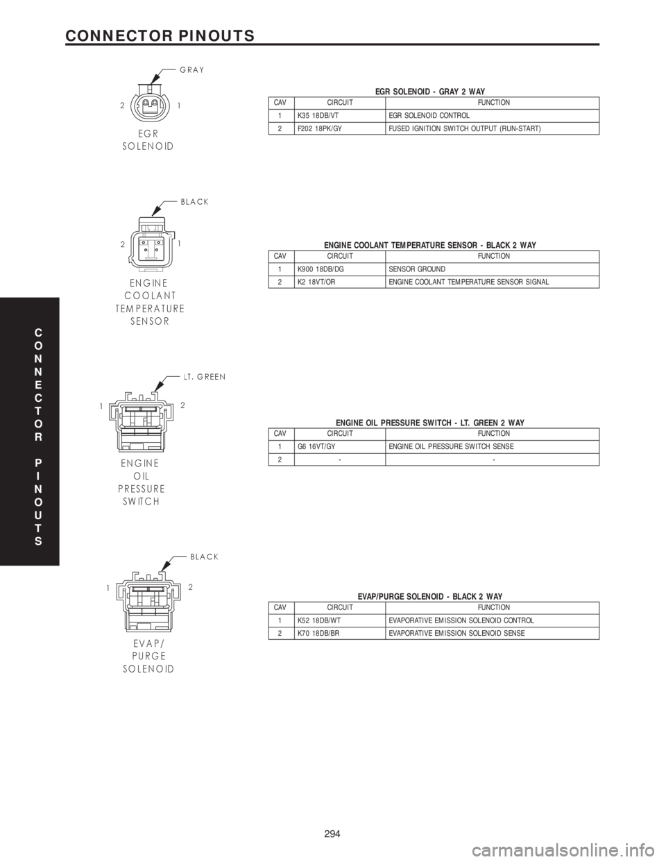
EGR SOLENOID - GRAY 2 WAYCAV CIRCUIT FUNCTION
1 K35 18DB/VT EGR SOLENOID CONTROL
2 F202 18PK/GY FUSED IGNITION SWITCH OUTPUT (RUN-START)
ENGINE COOLANT TEMPERATURE SENSOR - BLACK 2 WAYCAV CIRCUIT FUNCTION
1 K900 18DB/DG SENSOR GROUND
2 K2 18VT/OR ENGINE COOLANT TEMPERATURE SENSOR SIGNAL
ENGINE OIL PRESSURE SWITCH - LT. GREEN 2 WAYCAV CIRCUIT FUNCTION
1 G6 16VT/GY ENGINE OIL PRESSURE SWITCH SENSE
2- -
EVAP/PURGE SOLENOID - BLACK 2 WAYCAV CIRCUIT FUNCTION
1 K52 18DB/WT EVAPORATIVE EMISSION SOLENOID CONTROL
2 K70 18DB/BR EVAPORATIVE EMISSION SOLENOID SENSE
C
O
N
N
E
C
T
O
R
P
I
N
O
U
T
S
294
CONNECTOR PINOUTS
Page 4094 of 4284
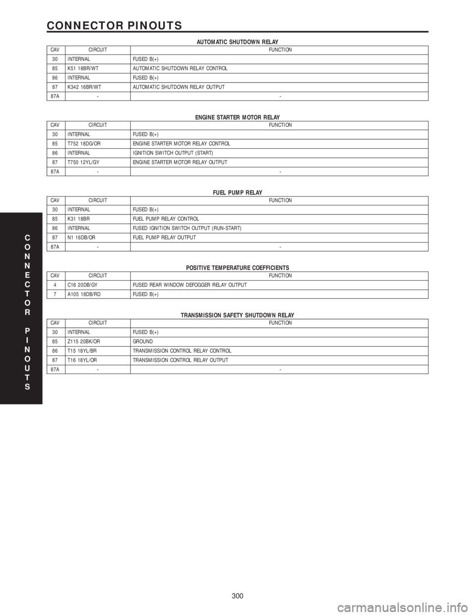
AUTOMATIC SHUTDOWN RELAYCAV CIRCUIT FUNCTION
30 INTERNAL FUSED B(+)
85 K51 18BR/WT AUTOMATIC SHUTDOWN RELAY CONTROL
86 INTERNAL FUSED B(+)
87 K342 16BR/WT AUTOMATIC SHUTDOWN RELAY OUTPUT
87A --
ENGINE STARTER MOTOR RELAYCAV CIRCUIT FUNCTION
30 INTERNAL FUSED B(+)
85 T752 18DG/OR ENGINE STARTER MOTOR RELAY CONTROL
86 INTERNAL IGNITION SWITCH OUTPUT (START)
87 T750 12YL/GY ENGINE STARTER MOTOR RELAY OUTPUT
87A --
FUEL PUMP RELAYCAV CIRCUIT FUNCTION
30 INTERNAL FUSED B(+)
85 K31 18BR FUEL PUMP RELAY CONTROL
86 INTERNAL FUSED IGNITION SWITCH OUTPUT (RUN-START)
87 N1 16DB/OR FUEL PUMP RELAY OUTPUT
87A --
POSITIVE TEMPERATURE COEFFICIENTSCAV CIRCUIT FUNCTION
4 C16 20DB/GY FUSED REAR WINDOW DEFOGGER RELAY OUTPUT
7 A105 18DB/RD FUSED B(+)
TRANSMISSION SAFETY SHUTDOWN RELAYCAV CIRCUIT FUNCTION
30 INTERNAL FUSED B(+)
85 Z115 20BK/OR GROUND
86 T15 18YL/BR TRANSMISSION CONTROL RELAY CONTROL
87 T16 18YL/OR TRANSMISSION CONTROL RELAY OUTPUT
87A --
C
O
N
N
E
C
T
O
R
P
I
N
O
U
T
S
300
CONNECTOR PINOUTS
Page 4095 of 4284
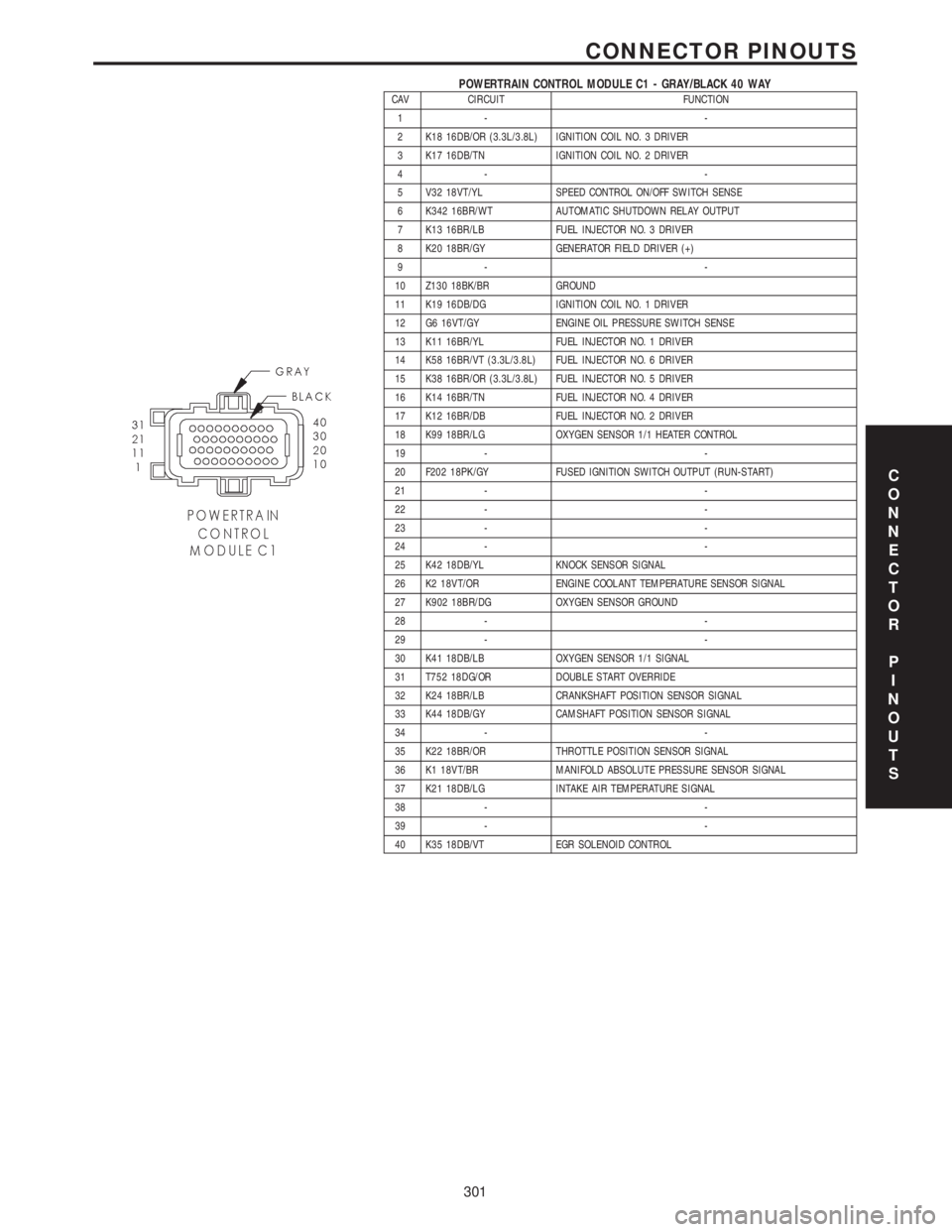
POWERTRAIN CONTROL MODULE C1 - GRAY/BLACK 40 WAYCAV CIRCUIT FUNCTION
1- -
2 K18 16DB/OR (3.3L/3.8L) IGNITION COIL NO. 3 DRIVER
3 K17 16DB/TN IGNITION COIL NO. 2 DRIVER
4- -
5 V32 18VT/YL SPEED CONTROL ON/OFF SWITCH SENSE
6 K342 16BR/WT AUTOMATIC SHUTDOWN RELAY OUTPUT
7 K13 16BR/LB FUEL INJECTOR NO. 3 DRIVER
8 K20 18BR/GY GENERATOR FIELD DRIVER (+)
9- -
10 Z130 18BK/BR GROUND
11 K19 16DB/DG IGNITION COIL NO. 1 DRIVER
12 G6 16VT/GY ENGINE OIL PRESSURE SWITCH SENSE
13 K11 16BR/YL FUEL INJECTOR NO. 1 DRIVER
14 K58 16BR/VT (3.3L/3.8L) FUEL INJECTOR NO. 6 DRIVER
15 K38 16BR/OR (3.3L/3.8L) FUEL INJECTOR NO. 5 DRIVER
16 K14 16BR/TN FUEL INJECTOR NO. 4 DRIVER
17 K12 16BR/DB FUEL INJECTOR NO. 2 DRIVER
18 K99 18BR/LG OXYGEN SENSOR 1/1 HEATER CONTROL
19 - -
20 F202 18PK/GY FUSED IGNITION SWITCH OUTPUT (RUN-START)
21 - -
22 - -
23 - -
24 - -
25 K42 18DB/YL KNOCK SENSOR SIGNAL
26 K2 18VT/OR ENGINE COOLANT TEMPERATURE SENSOR SIGNAL
27 K902 18BR/DG OXYGEN SENSOR GROUND
28 - -
29 - -
30 K41 18DB/LB OXYGEN SENSOR 1/1 SIGNAL
31 T752 18DG/OR DOUBLE START OVERRIDE
32 K24 18BR/LB CRANKSHAFT POSITION SENSOR SIGNAL
33 K44 18DB/GY CAMSHAFT POSITION SENSOR SIGNAL
34 - -
35 K22 18BR/OR THROTTLE POSITION SENSOR SIGNAL
36 K1 18VT/BR MANIFOLD ABSOLUTE PRESSURE SENSOR SIGNAL
37 K21 18DB/LG INTAKE AIR TEMPERATURE SIGNAL
38 - -
39 - -
40 K35 18DB/VT EGR SOLENOID CONTROL
C
O
N
N
E
C
T
O
R
P
I
N
O
U
T
S
301
CONNECTOR PINOUTS
Page 4102 of 4284
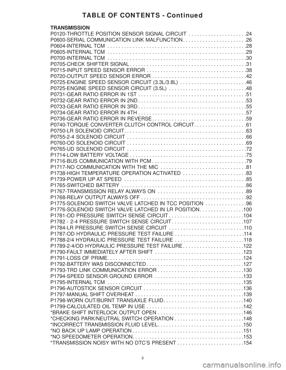
TABLE OF CONTENTS - Continued
TRANSMISSION
P0120-THROTTLE POSITION SENSOR SIGNAL CIRCUIT.....................24
P0600-SERIAL COMMUNICATION LINK MALFUNCTION.......................26
P0604-INTERNAL TCM..................................................28
P0605-INTERNAL TCM..................................................29
P0700-INTERNAL TCM..................................................30
P0705-CHECK SHIFTER SIGNAL..........................................31
P0715-INPUT SPEED SENSOR ERROR....................................38
P0720-OUTPUT SPEED SENSOR ERROR..................................42
P0725-ENGINE SPEED SENSOR CIRCUIT (3.3L/3.8L)........................46
P0725-ENGINE SPEED SENSOR CIRCUIT (3.5L)............................48
P0731-GEAR RATIO ERROR IN 1ST.......................................51
P0732-GEAR RATIO ERROR IN 2ND.......................................53
P0733-GEAR RATIO ERROR IN 3RD.......................................55
P0734-GEAR RATIO ERROR IN 4TH.......................................57
P0736-GEAR RATIO ERROR IN REVERSE..................................59
P0740-TORQUE CONVERTER CLUTCH CONTROL CIRCUIT...................61
P0750-LR SOLENOID CIRCUIT............................................63
P0755-2-4 SOLENOID CIRCUIT...........................................66
P0760-OD SOLENOID CIRCUIT...........................................69
P0765-UD SOLENOID CIRCUIT...........................................72
P1714-LOW BATTERY VOLTAGE..........................................75
P1716-BUS COMMUNICATION WITH PCM..................................79
P1717-NO COMMUNICATION WITH THE MIC...............................81
P1738-HIGH TEMPERATURE OPERATION ACTIVATED.......................83
P1739-POWER UP AT SPEED............................................85
P1765-SWITCHED BATTERY.............................................86
P1767-TRANSMISSION RELAY ALWAYS ON................................89
P1768-RELAY OUTPUT ALWAYS OFF......................................92
P1775-SOLENOID SWITCH VALVE LATCHED IN TCC POSITION...............96
P1776-SOLENOID SWITCH VALVE LATCHED IN LR POSITION................100
P1781-OD PRESSURE SWITCH SENSE CIRCUIT...........................104
P1782 - 2-4 PRESSURE SWITCH SENSE CIRCUIT..........................107
P1784-LR PRESSURE SWITCH SENSE CIRCUIT...........................110
P1787-OD HYDRAULIC PRESSURE TEST FAILURE.........................114
P1788-2/4 HYDRAULIC PRESSURE TEST FAILURE.........................118
P1789-2-4/OD HYDRAULIC PRESSURE TEST FAILURE......................122
P1790-FAULT IMMEDIATELY AFTER SHIFT................................123
P1791-LOSS OF PRIME.................................................124
P1792-BATTERY WAS DISCONNECTED...................................127
P1793-TRD LINK COMMUNICATION ERROR...............................130
P1794-SPEED SENSOR GROUND ERROR................................133
P1795-INTERNAL TCM.................................................135
P1796-AUTOSTICK SENSOR CIRCUIT....................................136
P1797-MANUAL SHIFT OVERHEAT.......................................139
P1798-WORN OUT/BURNT TRANSAXLE FLUID.............................140
P1799-CALCULATED OIL TEMP IN USE...................................142
*BRAKE SHIFT INTERLOCK OUTPUT OPEN...............................146
*CHECKING PARK/NEUTRAL SWITCH OPERATION.........................148
*INCORRECT TRANSMISSION FLUID LEVEL...............................150
*NO BACK UP LAMP OPERATION........................................151
*NO SPEEDOMETER OPERATION........................................153
*TRANSMISSION NOISY WITH NO DTC'S PRESENT........................154
ii
Page 4105 of 4284
1.0 INTRODUCTION
The procedures contained in this manual include
all of the specifications, instructions, and graphics
needed to diagnose 41TE/AE Electronic Automatic
Transaxle (EATX) problems. The diagnostics in this
manual are based on the failure condition or symp-
tom being present at the time of diagnosis.
When repairs are required, refer to the appropri-
ate volume of the service manual for the proper
removal and repair procedure.
Diagnostic procedures change every year. New
diagnostic systems may be added and/or carryover
systems may be enhanced. READ THIS MANUAL
BEFORE TRYING TO DIAGNOSE A VEHICLE
TROUBLE CODE. It is recommended that you
review the entire manual to become familiar with
all new and changed diagnostic procedures.
This book reflects many suggested changes from
readers of past issues. After using this book, if you
have any comments or recommendations, please fill
out the form at the back of the book and mail it back
to us.
1.1 SYSTEM COVERAGE
This diagnostic procedures manual covers all
2001 RG equipped with a 41TE/AE transaxle.
1.2 SIX -STEP TROUBLESHOOTING
PROCEDURE
Diagnosis of the 41TE/AE electronic transaxle is
done in six basic steps:
verification of complaint
verification of any related symptoms
symptom analysis
problem isolation
repair of isolated problem
verification of proper operation
2.0 IDENTIFICATION OF
SYSTEM
RG series vehicles equipped with a 4 speed trans-
mission.
3.0 SYSTEM DESCRIPTION AND
FUNCTIONAL OPERATION
3.1 GENERAL DESCRIPTION
The 41TE/AE electronic transaxle is a conven-
tional transaxle in that it uses hydraulically ap-
plied clutches to shift a planetary gear train. How-
ever, the electronic control system replaces many of
the mechanical and hydraulic components used in
conventional transmission valve bodies.
3.2 FUNCTIONAL OPERATION
The 41TE/AE electronic transaxle has a fully
adaptive control system. The system performs it's
functions based on continuous real-time sensor
feedback information. The control system automat-
ically adapts to changes in engine performance and
friction element variations to provide consistent
shift quality. The control system ensures that clutch
operation during upshifting and downshifting is
more responsive without increased harshness.
The Transmission Control Module (TCM) contin-
uously checks for electrical problems, mechanical
problems, and some hydraulic problems. When a
problem is sensed, the TCM stores a diagnostic
trouble code. Some of these codes cause the tran-
saxle to go into limp-in or default mode.
While in this mode, electrical power is taken
away from the transaxle via the TCM, de-
energizing the transmission control relay, and tak-
ing power from the solenoid pack. When this hap-
pens, the only transaxle mechanical functions are:
Park and Neutral
Reverse
Second Gear
No upshifts or downshifts are possible. The posi-
tion of the manual valve alone allows the three
ranges that are available. Although vehicle perfor-
mance is seriously degraded while in this mode, it
allows the owner to drive the vehicle in for service.
Once the DRBIIItis in the EATX portion of the
diagnostic program, it constantly monitors the
TCM to see if the system is in limp-in mode. If the
transaxle is in limp-in mode, the DRBIIIž will flash
the red LED.
3.2.1 AUTOSTICK FEATURE
This feature allows the driver to manually shift
the transaxle when the shift lever is pulled back
into the AutoStick position. When in AutoStick
mode, the instrument cluster displays the current
gear.
1
GENERAL INFORMATION
Page 4106 of 4284
3.2.2 TRANSMISSION OPERATION AND
SHIFT SCHEDULING AT VARIOUS
OIL TEMPERATURES.
The transmission covered in this manual has
unique shift schedules depending on the tempera-
ture of the transmission oil. The shift schedule is
modified to extend the life of the transmission while
operating under extreme conditions.
The oil temperature is measured with a Temper-
ature Sensor on the 41TE/AE transmission. The
Temperature Sensor is an integral component of the
Transmission Range Sensor (TRS). If the Tempera-
ture Sensor is faulty, (DTC P1799(74)) the trans-
mission will default to a calculated oil temperature.
Oil temperature will then be calculated through a
complex heat transfer equation which uses engine
coolant temperature, battery/ambient temperature,
and engine off time from the Body Control Module
(BCM). These inputs are received from the PCI bus
periodically and used to initialize the oil tempera-
ture at start up. Once the engine is started, the
TCM updates the transmission oil temperature
based on torque converter slip speed, vehicle speed,
gear, and engine coolant temperature to determine
an estimated oil temperature during vehicle opera-
tion. Vehicles using a calculated oil temperature
track oil temperature reasonably accurate during
normal operation. However, if a transmission is
overfilled, a transmission oil cooler becomes re-
stricted, or if a customer drives aggressively in low
gear, the calculated oil temperature will be inaccu-
rate. Consequently the shift schedule selected may
be inappropriate for the current conditions. The key
highlights of the various shift schedules are as
follows:
Extreme Cold:Oil temperature at start up below
-26.6C (-16ÉF)
> Goes to a Cold schedule above -24C (-12ÉF) oil
temperature
> Park, Reverse, Neutral and 2nd gear only (pre-
vents shifting which may fail a clutch with fre-
quent shifts)
Cold:Oil temperature at start up above -24C
(-12ÉF) and below 2.2C (36ÉF)
> Goes to a Warm schedule above 4.4C (40ÉF) oil
temperature
> Delayed 2-3 upshift approximately 35-50 Km/h
(22-31 MPH)
> Delayed 3-4 upshift 72-85 Km/h (45-53 MPH)
> Early 4-3 coastdown shift approximately 48
Km/h (30 MPH)
> Early 3-2 coastdown shift approximately 27
Km/h (17 MPH)> High speed 4-2, 3-2, 2-1 kickdown shifts are
prevented
> No EMCC
Warm:Oil temperature at start up above 2.2C
(36ÉF) and below 27C (80ÉF)
> Goes to a Hot schedule above 27C (80ÉF) oil
temperature
> Normal operation (upshifts, kickdowns, and
coastdowns)
> No EMCC
Hot:Oil temperature at start up above 27C (80ÉF)
> Goes to a Overheat schedule above 115C (240ÉF)
oil temperature
> Normal operation (upshifts, kickdowns, and
coastdowns)
> Full EMCC, No PEMCC except to engage
FEMCC
(Except at closed throttle at speeds above 113-133
Km/h (70 - 83 MPH)
Overheat:Oil temperature above 115C (240ÉF) or
engine coolant temperature above 118C (244ÉF)
> Goes to a Hot below 110C (230ÉF) oil temperature
or a Super Overheat above 115C (240ÉF) oil
temperature
> Delayed 2-3 upshift 40-51 Km/h (25-32 MPH)
> Delayed 3-4 upshift 66-77 Km/h (41-48 MPH)
> 3rd gear FEMCC from 48-77 Km/h (30-48 MPH)
> 3rd gear PEMCC from 43-50 Km/h (27-31 MPH)
Super Overheat:Oil temperature above 127C
(260ÉF)
> Goes back to a Overheat below 115C (240ÉF) oil
temperature
> All a Overheat shift schedules features apply
> 2nd gear PEMCC above 35 Km/h (22 MPH)
> Above 35 Km/h (22 MPH) the torque converter
will not unlock unless the throttle is closed (i.e. at
80 Km/h (50 MPH) a 4th FEMCC to 3rd FEMCC
shift will be made during a part throttle kick-
down or a 4th FEMCC to 2nd PEMCC shift will
be made at wide open throttle) or if a wide open
throttle 2nd PEMCC to 1 kickdown is made.
Causes for operation in the wrong tempera-
ture shift schedule:
Extreme Cold or Cold shift schedule at start up:
> Temperature Sensor circuit.
Overheat or Super Overheat shift schedule after
extended operation:
> Operation in city traffic or stop and go traffic
> Engine idle speed too high
> Aggressive driving in low gear
2
GENERAL INFORMATION