ESP CHRYSLER VOYAGER 2001 Service Manual
[x] Cancel search | Manufacturer: CHRYSLER, Model Year: 2001, Model line: VOYAGER, Model: CHRYSLER VOYAGER 2001Pages: 4284, PDF Size: 83.53 MB
Page 975 of 4284
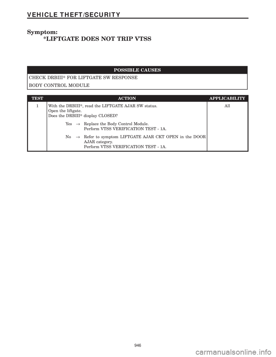
Symptom:
*LIFTGATE DOES NOT TRIP VTSS
POSSIBLE CAUSES
CHECK DRBIIItFOR LIFTGATE SW RESPONSE
BODY CONTROL MODULE
TEST ACTION APPLICABILITY
1 With the DRBIIIt, read the LIFTGATE AJAR SW status.
Open the liftgate.
Does the DRBIIItdisplay CLOSED?All
Ye s®Replace the Body Control Module.
Perform VTSS VERIFICATION TEST - 1A.
No®Refer to symptom LIFTGATE AJAR CKT OPEN in the DOOR
AJAR category.
Perform VTSS VERIFICATION TEST - 1A.
946
VEHICLE THEFT/SECURITY
Page 977 of 4284
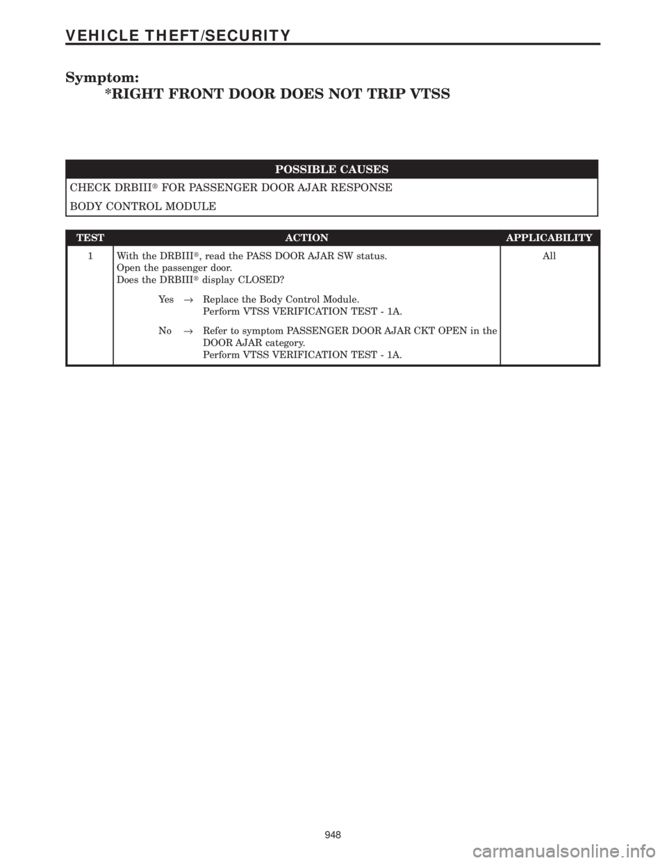
Symptom:
*RIGHT FRONT DOOR DOES NOT TRIP VTSS
POSSIBLE CAUSES
CHECK DRBIIItFOR PASSENGER DOOR AJAR RESPONSE
BODY CONTROL MODULE
TEST ACTION APPLICABILITY
1 With the DRBIIIt, read the PASS DOOR AJAR SW status.
Open the passenger door.
Does the DRBIIItdisplay CLOSED?All
Ye s®Replace the Body Control Module.
Perform VTSS VERIFICATION TEST - 1A.
No®Refer to symptom PASSENGER DOOR AJAR CKT OPEN in the
DOOR AJAR category.
Perform VTSS VERIFICATION TEST - 1A.
948
VEHICLE THEFT/SECURITY
Page 978 of 4284
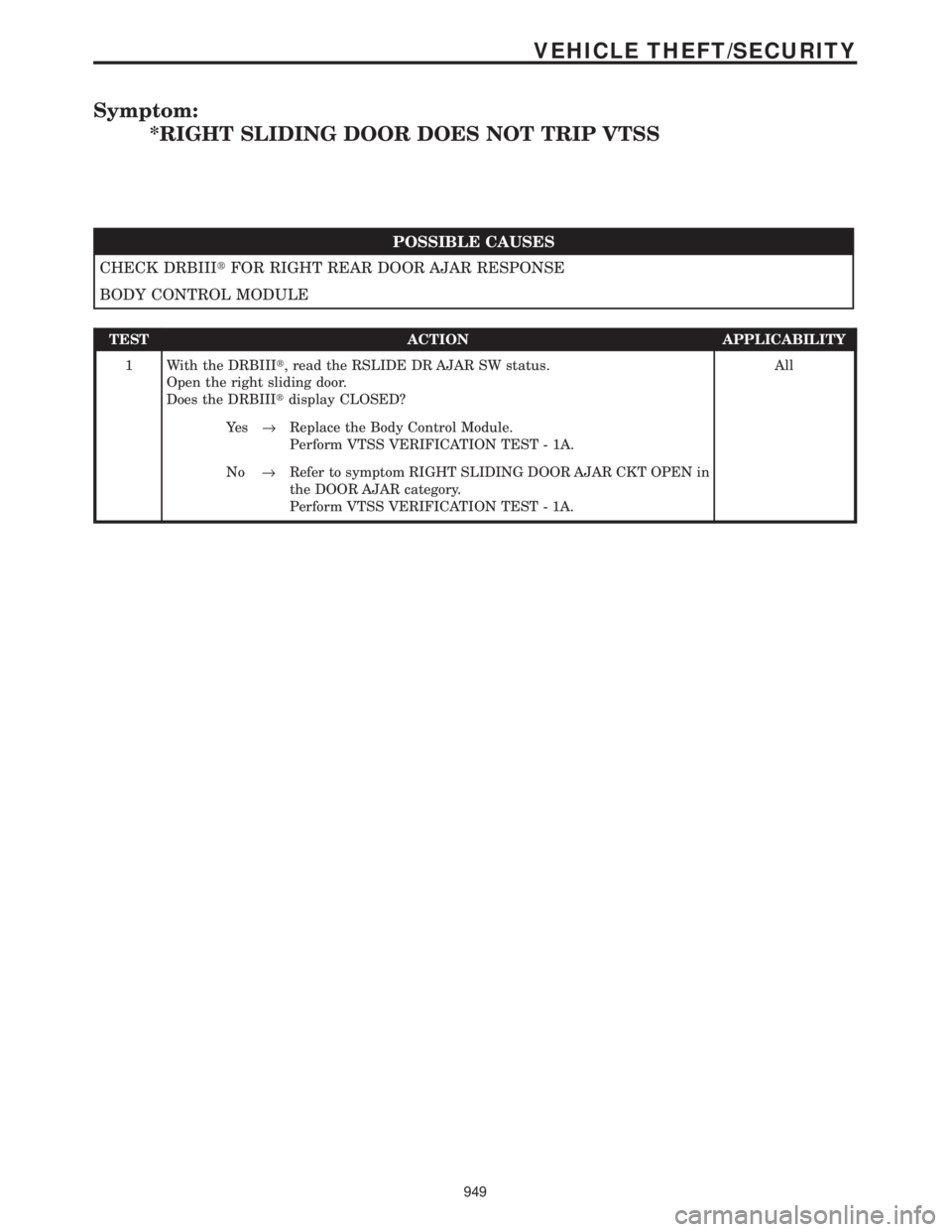
Symptom:
*RIGHT SLIDING DOOR DOES NOT TRIP VTSS
POSSIBLE CAUSES
CHECK DRBIIItFOR RIGHT REAR DOOR AJAR RESPONSE
BODY CONTROL MODULE
TEST ACTION APPLICABILITY
1 With the DRBIIIt, read the RSLIDE DR AJAR SW status.
Open the right sliding door.
Does the DRBIIItdisplay CLOSED?All
Ye s®Replace the Body Control Module.
Perform VTSS VERIFICATION TEST - 1A.
No®Refer to symptom RIGHT SLIDING DOOR AJAR CKT OPEN in
the DOOR AJAR category.
Perform VTSS VERIFICATION TEST - 1A.
949
VEHICLE THEFT/SECURITY
Page 1019 of 4284

BODY VERIFICATION TEST - VER 1 APPLICABILITY
1. Disconnect all jumper wires and reconnect all previously disconnected components and
connectors.
2. With the DRBIIIt, record and erase all DTCs from ALL modules. Cycle the ignition on then
off
3. If the Sentry Key Immobilizer Module (SKIM), the Powertrain Control Module (PCM), or the
Engine Control Module (ECM) was replaced, proceed to number 9. If the SKIM, PCM, or ECM
was not replaced, continue to the next number.
4. If the Body Control Module (BCM) was replaced, turn the ignition on for 15 seconds (to allow
the new BCM to learn VIN) or engine may not start (if VTSS equipped). If the vehicle is
equipped with VTSS, use the DRBIIItand enable VTSS.
5. Program all other options as needed.
6. If any actuators were replaced in the HVAC System, with the DRBIIItin HVAC, select
System Tests then select HVAC Door Recalibration (manual temperature system only).
7. If any actuators were replaced in the ATC System, with the DRBIIItin Automatic Temp
Control, select Miscellaneous then select Reset ATC Head.
8. If any repairs were made to the power sliding door or power liftgate, use the DRBIIItand
perform the open and close system tests. Observe the instructions on the DRBIIItscreen.
Proceed to number 16.
9. Obtain the vehicle's unique PIN assigned to it's original SKIM from either the vehicle's
invoice or from Chrysler's Customer Assistance Center (1-800-992-1997).
10. NOTE: Once Secured Access Mode is active, the SKIM will remain in that mode for 60
seconds.
11. With the DRBIIIt, select THEFT ALARM, SKIM, MISCELLANEOUS and select SKIM
REPLACED. Enter the 4 digit PIN to put the SKIM in Secured Access Mode.
12. The DRBIIItwill prompt for the following steps. (1) Program the country code into the
SKIM's memory. (2) Program the vehicle's VIN into the SKIM memory. (3) Transfer the
vehicle's Secret Key data from the PCM.
13. Using the DRBIIIt, program all customer keys into the SKIM memory. This requires that
the SKIM be in Secured Access Mode, using the 4 digit PIN.
14. Note: If the PCM or ECM is replaced, the VIN and the unique Secret Key data must be
transferred from the SKIM to the PCM or ECM. This procedure requires the SKIM to be placed
in Secured Access Mode using the 4-digit PIN.
15. Note: If 3 attempts are made to enter Secured Access Mode using an incorrect PIN, Secured
Access Mode will be locked out for 1 hour which causes the DRBIIItto display9No Resp from
SKIM9. To exit this mode, turn ignition to Run for 1 hour.
16. Ensure that all accessories are turned off and the battery is fully charged.
17. Start and run the engine for 2 minutes. Operate all functions of the system that caused the
original concern.
18. Turn the ignition off and wait 5 seconds. Turn the ignition on and using the DRBIIIt, read
DTCs from ALL modules.
Are any DTC's present or is the original condition still present?All
Ye s®Repair is not complete, refer to the appropriate symptom.
No®Repair is complete.
990
VERIFICATION TESTS
Verification Tests ÐContinued
Page 1020 of 4284
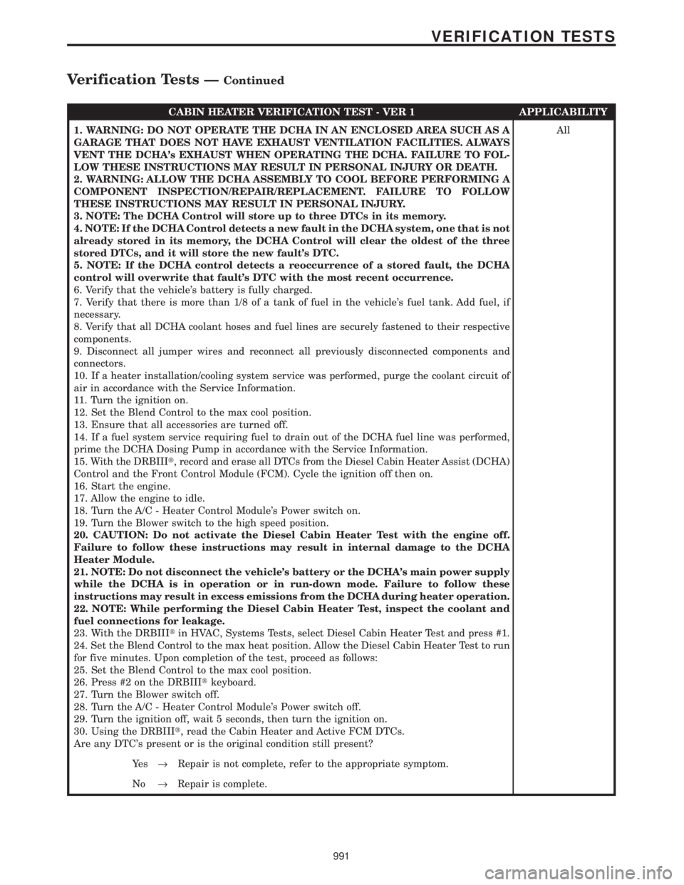
CABIN HEATER VERIFICATION TEST - VER 1 APPLICABILITY
1. WARNING: DO NOT OPERATE THE DCHA IN AN ENCLOSED AREA SUCH AS A
GARAGE THAT DOES NOT HAVE EXHAUST VENTILATION FACILITIES. ALWAYS
VENT THE DCHA's EXHAUST WHEN OPERATING THE DCHA. FAILURE TO FOL-
LOW THESE INSTRUCTIONS MAY RESULT IN PERSONAL INJURY OR DEATH.
2. WARNING: ALLOW THE DCHA ASSEMBLY TO COOL BEFORE PERFORMING A
COMPONENT INSPECTION/REPAIR/REPLACEMENT. FAILURE TO FOLLOW
THESE INSTRUCTIONS MAY RESULT IN PERSONAL INJURY.
3. NOTE: The DCHA Control will store up to three DTCs in its memory.
4. NOTE: If the DCHA Control detects a new fault in the DCHA system, one that is not
already stored in its memory, the DCHA Control will clear the oldest of the three
stored DTCs, and it will store the new fault's DTC.
5. NOTE: If the DCHA control detects a reoccurrence of a stored fault, the DCHA
control will overwrite that fault's DTC with the most recent occurrence.
6. Verify that the vehicle's battery is fully charged.
7. Verify that there is more than 1/8 of a tank of fuel in the vehicle's fuel tank. Add fuel, if
necessary.
8. Verify that all DCHA coolant hoses and fuel lines are securely fastened to their respective
components.
9. Disconnect all jumper wires and reconnect all previously disconnected components and
connectors.
10. If a heater installation/cooling system service was performed, purge the coolant circuit of
air in accordance with the Service Information.
11. Turn the ignition on.
12. Set the Blend Control to the max cool position.
13. Ensure that all accessories are turned off.
14. If a fuel system service requiring fuel to drain out of the DCHA fuel line was performed,
prime the DCHA Dosing Pump in accordance with the Service Information.
15. With the DRBIIIt, record and erase all DTCs from the Diesel Cabin Heater Assist (DCHA)
Control and the Front Control Module (FCM). Cycle the ignition off then on.
16. Start the engine.
17. Allow the engine to idle.
18. Turn the A/C - Heater Control Module's Power switch on.
19. Turn the Blower switch to the high speed position.
20. CAUTION: Do not activate the Diesel Cabin Heater Test with the engine off.
Failure to follow these instructions may result in internal damage to the DCHA
Heater Module.
21. NOTE: Do not disconnect the vehicle's battery or the DCHA's main power supply
while the DCHA is in operation or in run-down mode. Failure to follow these
instructions may result in excess emissions from the DCHA during heater operation.
22. NOTE: While performing the Diesel Cabin Heater Test, inspect the coolant and
fuel connections for leakage.
23. With the DRBIIItin HVAC, Systems Tests, select Diesel Cabin Heater Test and press #1.
24. Set the Blend Control to the max heat position. Allow the Diesel Cabin Heater Test to run
for five minutes. Upon completion of the test, proceed as follows:
25. Set the Blend Control to the max cool position.
26. Press #2 on the DRBIIItkeyboard.
27. Turn the Blower switch off.
28. Turn the A/C - Heater Control Module's Power switch off.
29. Turn the ignition off, wait 5 seconds, then turn the ignition on.
30. Using the DRBIIIt, read the Cabin Heater and Active FCM DTCs.
Are any DTC's present or is the original condition still present?All
Ye s®Repair is not complete, refer to the appropriate symptom.
No®Repair is complete.
991
VERIFICATION TESTS
Verification Tests ÐContinued
Page 1021 of 4284
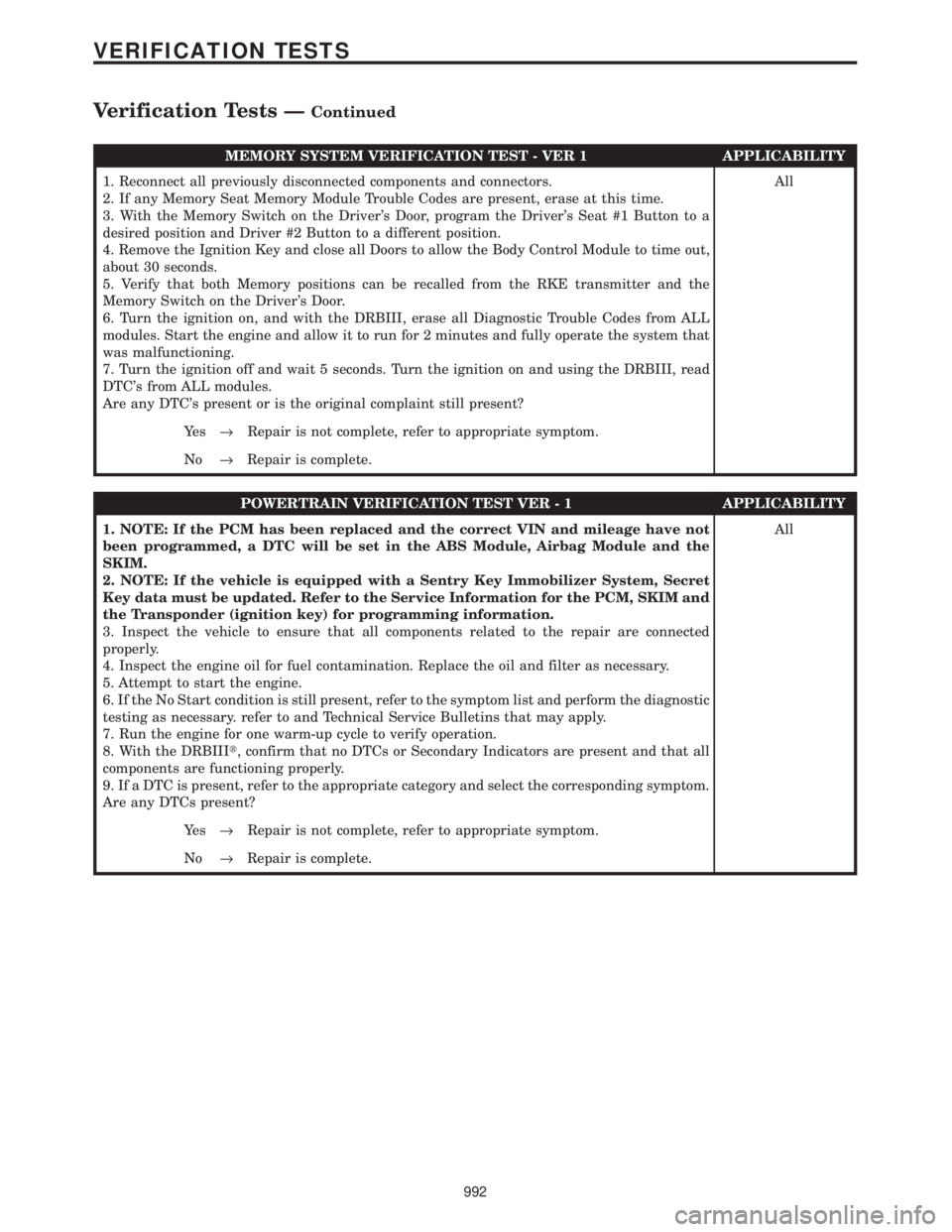
MEMORY SYSTEM VERIFICATION TEST - VER 1 APPLICABILITY
1. Reconnect all previously disconnected components and connectors.
2. If any Memory Seat Memory Module Trouble Codes are present, erase at this time.
3. With the Memory Switch on the Driver's Door, program the Driver's Seat #1 Button to a
desired position and Driver #2 Button to a different position.
4. Remove the Ignition Key and close all Doors to allow the Body Control Module to time out,
about 30 seconds.
5. Verify that both Memory positions can be recalled from the RKE transmitter and the
Memory Switch on the Driver's Door.
6. Turn the ignition on, and with the DRBIII, erase all Diagnostic Trouble Codes from ALL
modules. Start the engine and allow it to run for 2 minutes and fully operate the system that
was malfunctioning.
7. Turn the ignition off and wait 5 seconds. Turn the ignition on and using the DRBIII, read
DTC's from ALL modules.
Are any DTC's present or is the original complaint still present?All
Ye s®Repair is not complete, refer to appropriate symptom.
No®Repair is complete.
POWERTRAIN VERIFICATION TEST VER - 1 APPLICABILITY
1. NOTE: If the PCM has been replaced and the correct VIN and mileage have not
been programmed, a DTC will be set in the ABS Module, Airbag Module and the
SKIM.
2. NOTE: If the vehicle is equipped with a Sentry Key Immobilizer System, Secret
Key data must be updated. Refer to the Service Information for the PCM, SKIM and
the Transponder (ignition key) for programming information.
3. Inspect the vehicle to ensure that all components related to the repair are connected
properly.
4. Inspect the engine oil for fuel contamination. Replace the oil and filter as necessary.
5. Attempt to start the engine.
6. If the No Start condition is still present, refer to the symptom list and perform the diagnostic
testing as necessary. refer to and Technical Service Bulletins that may apply.
7. Run the engine for one warm-up cycle to verify operation.
8. With the DRBIIIt, confirm that no DTCs or Secondary Indicators are present and that all
components are functioning properly.
9. If a DTC is present, refer to the appropriate category and select the corresponding symptom.
Are any DTCs present?All
Ye s®Repair is not complete, refer to appropriate symptom.
No®Repair is complete.
992
VERIFICATION TESTS
Verification Tests ÐContinued
Page 1158 of 4284

1.0 INTRODUCTION
The procedures contained in this manual include
all the specifications, instructions, and graphics
needed to diagnose Mark 20 Antilock Braking Sys-
tem (ABS) and Mark 20 Antilock Braking System
with Traction Control. The diagnostics in this man-
ual are based on the failure condition or symptom
being present at time of diagnosis.
Please follow the recommendations below when
choosing your diagnostic path.
1. First make sure the DRBIIItis communicating
with the CAB. If the DRBIIItdisplays a ªNo
Responseº condition, you must diagnose that
first.
2. Read DTC's (diagnostic trouble codes) with the
DRBIIIt.
3. If no DTC's are present, identify the customer
complaint.
4. Once the DTC or customer complaint is identi-
fied, locate the matching test in the Table of
Contents and begin to diagnose the symptom.
All component location views are in Section 8.0.
All connector pinouts are in Section 9.0. All sche-
matics are in Section 10.0.
An * placed before the symptom description indi-
cates a concern with no associated DTC.
When repairs are required, refer to the appropri-
ate service manual for the proper removal and
repair procedure.
Diagnostic procedures change every year. New
diagnostic systems may be added; carry over sys-
tems may be enhanced. READ THIS MANUAL
BEFORE TRYING TO DIAGNOSE A VEHICLE
CODE. It is recommended that you review the
entire manual to become familiar with all new and
changed diagnostic procedures.
After using this book, if you have any comments
or recommendations, please fill out the form at the
back of the book and mail it back to us.
1.1 SYSTEM COVERAGE
This diagnostic procedure manual covers the an-
tilock braking system (ABS) and traction control
system found on: 2001 Chrysler Town and Country,
Dodge Caravan and Grand Caravan.
1.2 SIX-STEP TROUBLESHOOTING
PROCEDURE
Diagnosis of the controller antilock brake module
is done in six basic steps:
²verification of complaint
²verification of any related symptoms
²symptom analysis
²problem isolation
²repair of isolated problem
²verification of proper operation
2.0 IDENTIFICATION OF
SYSTEM
Vehicles equipped with the Teves Mark 20 an-
tilock brake system can be identified by the pres-
ence of the controller antilock brake module located
beneath the master cylinder.
3.0 SYSTEM DESCRIPTION AND
FUNCTIONAL OPERATION
3.1 TEVES MARK 20 SYSTEM
DESCRIPTION
The controller antilock brake module is used to
monitor wheel speeds and to modulate (control)
hydraulic pressure in each brake channel. The
modulated hydraulic pressure is used to prevent
wheel lock-up during braking.
The Teves Mark 20 system uses a diagonal split
hydraulic brake system.
In the standard brake mode
the master cylinder primary circuit supplies pressure
to the right front and left rear wheel brakes, and the
secondary master cylinder circuit supplies pressure
to the left front and right rear wheel brakes.
3.2 TRACTION CONTROL SYSTEM (TCS)
DESCRIPTION
The main purpose of traction control is to reduce
wheel slip and maintain traction at the driven
wheels when road surfaces are slippery. The trac-
tion control system reduces wheel slip by braking
the wheel that is losing traction. The system is
designed to operate at speeds below 56 km/h (35
mph).
The Controller Antilock Brake (CAB) monitors
wheel speeds. If, during acceleration, the module
detects front (drive) wheel slip and the brakes are
not applied, the CAB will enter traction control
mode. Traction control works in the following order
when drive wheel slip is detected.
1. Close the (normally open) isolation valves.
2. Start pump/motor and supply volume/pressure
to front hydraulic circuits (pump runs continu-
ously during traction control).
3. Open and close build and decay valves to main-
tain minimum wheel slip and maximum trac-
tion.
1
GENERAL INFORMATION
Page 1161 of 4284
the brake pedal is applied the test will be run at 40
km/h (24 mph) regardless of brake switch state. If,
during the dynamic test, the brake pedal is applied,
the driver may feel the test through brake pedal
pulsations. This is a normal condition.
If any component exhibits a trouble condition
during system initialization or dynamic check, the
CAB will illuminate the ABS warning indicator and
TRAC OFF lamp if equipped.
3.3.6 DIAGNOSTIC MODE
To enter diagnostic mode, a vehicle speed must be
below 10 km/h (6 mph) and no ABS condition
present. If vehicle speed is not below 10 km/h
(6 mph), a ªNo Responseº message could be dis-
played by the DRBIIIt. The following are charac-
teristics of diagnostic mode:
± The amber ABS warning indicator will blink
rapidly (about 1/2 second ON and 1/2 second
OFF). If a hard trouble code, such as Valve
Power Feed Failure code is present, the indi-
cator will be illuminated without blinking un-
til the trouble condition is cleared.
± Antilock operation is disabled.
± The HCU valves cannot be actuated when the
vehicle speed is above 8 km/h (5 mph). If valve
actuation is attempted above 8 km/h (5 mph), a
ªNo Responseº message will be displayed on
the DRBIIIt.
3.4 DIAGNOSTIC TROUBLE CODES
The controller antilock brake may report any of
the following diagnostic trouble codes:
CLUSTER LAMP FAILURE
VALVE POWER FEED FAILURE
BUS SYSTEM COMMUNICATION FAILURE
CAB INTERNAL FAILURE
LEFT FRONT SENSOR CIRCUIT FAILURE
LEFT FRONT WHEEL SPEED SIGNAL
FAILURE
LEFT REAR SENSOR CIRCUIT FAILURE
LEFT REAR WHEEL SPEED SIGNAL
FAILURE
PUMP CIRCUIT FAILURE
RIGHT FRONT SENSOR CIRCUIT FAILURE
RIGHT FRONT WHEEL SPEED SIGNAL
FAILURE
RIGHT REAR SENSOR CIRCUIT FAILURE
RIGHT REAR WHEEL SPEED SIGNAL
FAILURE
SYSTEM OVERVOLTAGE
SYSTEM UNDERVOLTAGE
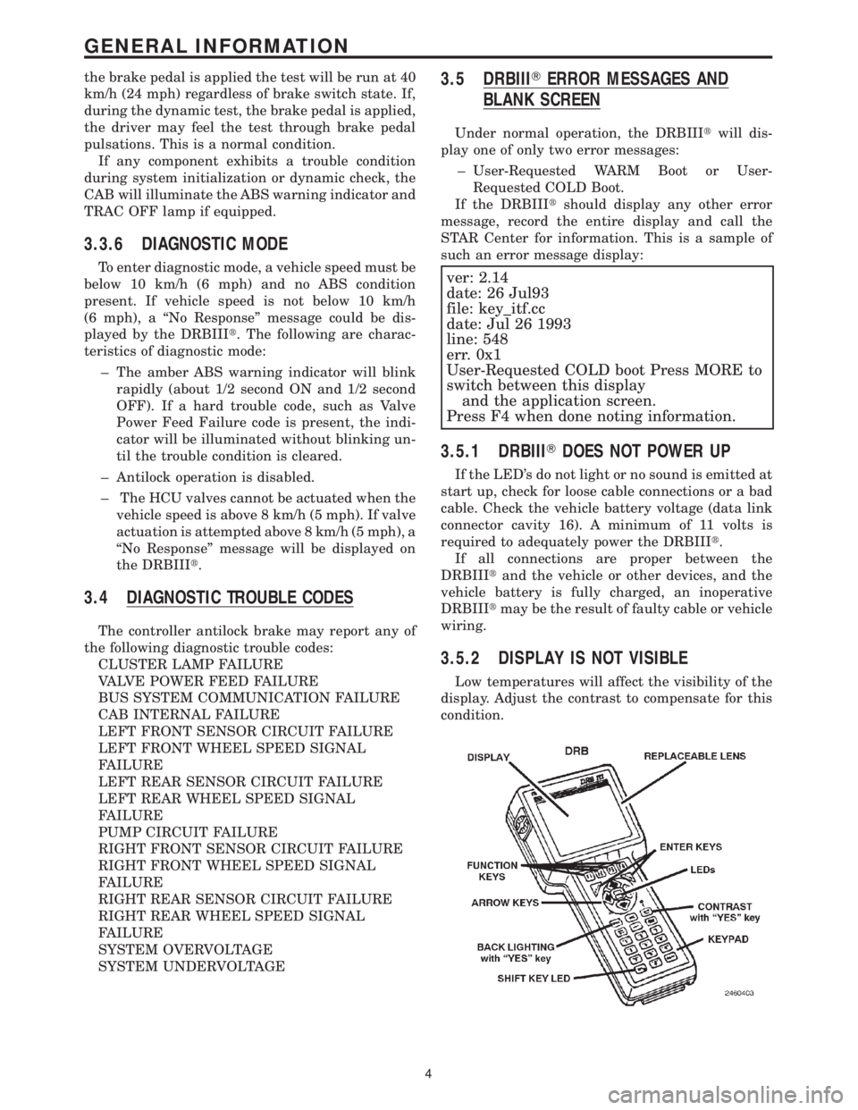
3.5 DRBIIITERROR MESSAGES AND
BLANK SCREEN
Under normal operation, the DRBIIItwill dis-
play one of only two error messages:
± User-Requested WARM Boot or User-
Requested COLD Boot.
If the DRBIIItshould display any other error
message, record the entire display and call the
STAR Center for information. This is a sample of
such an error message display:
ver: 2.14
date: 26 Jul93
file: key_itf.cc
date: Jul 26 1993
line: 548
err. 0x1
User-Requested COLD boot Press MORE to
switch between this display
and the application screen.
Press F4 when done noting information.
3.5.1 DRBIIITDOES NOT POWER UP
If the LED's do not light or no sound is emitted at
start up, check for loose cable connections or a bad
cable. Check the vehicle battery voltage (data link
connector cavity 16). A minimum of 11 volts is
required to adequately power the DRBIIIt.
If all connections are proper between the
DRBIIItand the vehicle or other devices, and the
vehicle battery is fully charged, an inoperative
DRBIIItmay be the result of faulty cable or vehicle
wiring.
3.5.2 DISPLAY IS NOT VISIBLE
Low temperatures will affect the visibility of the
display. Adjust the contrast to compensate for this
condition.
4
GENERAL INFORMATION
Page 1162 of 4284

4.0 DISCLAIMERS, SAFETY,
WARNINGS
4.1 DISCLAIMERS
All information, illustrations, and specifications
contained in this manual are based on the latest
information available at the time of publication.
The right is reserved to make changes at any time
without notice.
4.2 SAFETY
4.2.1 TECHNICIAN SAFETY INFORMATION
WARNING: ENGINES PRODUCE CARBON
MONOXIDE THAT IS ODORLESS, CAUSES
SLOWER REACTION TIME, AND CAN LEAD
TO SERIOUS INJURY. WHEN THE ENGINE IS
OPERATING, KEEP SERVICE AREAS WELL
VENTILATED OR ATTACH THE VEHICLE
EXHAUST SYSTEM TO THE SHOP EXHAUST
REMOVAL SYSTEM.
Set the parking brake and block the wheels before
testing or repairing the vehicle. It is especially
important to block the wheels on front-wheel drive
vehicles; the parking brake does not hold the drive
wheels.
When servicing a vehicle, always wear eye pro-
tection, and remove any metal jewelry such as
rings, watchbands or bracelets that might make an
inadvertent electrical contact.
When diagnosing a chassis problem, it is impor-
tant to follow approved procedures where applica-
ble. These procedures can be found in the service
manual. Following these procedures is very impor-
tant to the safety of individuals performing diag-
nostic tests.
4.2.2 VEHICLE PREPARATION FOR
TESTING
Make sure the vehicle being tested has a fully
charged battery. If is does not, false diagnostic codes
or error messages may occur.
4.2.3 SERVICING SUB-ASSEMBLIES
Some components of the chassis system are in-
tended to be serviced as an assembly only. Attempt-
ing to remove or repair certain system sub-
components may result in personal injury and/or
improper system operation. Only those components
with approved repair and installation procedures in
the service manual should be serviced.
4.2.4 DRBIIITSAFETY INFORMATION
WARNING: EXCEEDING THE LIMITS OF THE
DRB MULTIMETER IS DANGEROUS. IT CAN
EXPOSE YOU TO SERIOUS OR POSSIBLY
FATAL INJURY. CAREFULLY READ AND
UNDERSTAND THE CAUTIONS AND THE
SPECIFICATION LIMITS.
²Follow the vehicle manufacturer 's service speci-
fications at all times.
²Do not use the DRBIIItif it has been damaged.
²Do not use the test leads if the insulation is
damaged or if metal is exposed.
²To avoid electrical shock, do not touch the test
leads, tips, or the circuit being tested.
²Choose the proper range and functions for the
measurement. Do not try voltage or current mea-
surements that may exceed the rated capacity.
²Do not exceed the limits shown in the table below:
FUNCTION INPUT LIMIT
Volts 0 - 500 peak volts AC
0 - 500 volts DC
Ohms (resistance)* 0 -1.12 megohms
Frequency Measured
Frequency Generated0-10kHz
Temperature -58 - 1100ÉF
-50 - 600ÉC
* Ohms cannot be measured if voltage is present.
Ohms can be measured only in a non-powered
circuit.
²Voltage between any terminal and ground must
not exceed 500v DC or 500v peak AC.
²Use caution when measuring voltage above 25v
DC or 25v AC.
²Use the low current shunt to measure circuits up
to 10A. Use the high current clamp to measure
circuits exceeding 10A.
²When testing for the presence of voltage or cur-
rent, make sure the meter is functioning cor-
rectly. Take a reading of a known voltage or
current before accepting a zero reading.
²When measuring current, connect the meter in
series with the load.
²Disconnect the live test lead before disconnecting
the common test lead.
²When using the meter function, keep the
DRBIIItaway from spark plug or coil wires to
avoid measuring error from outside interference.
5
GENERAL INFORMATION
Page 1163 of 4284
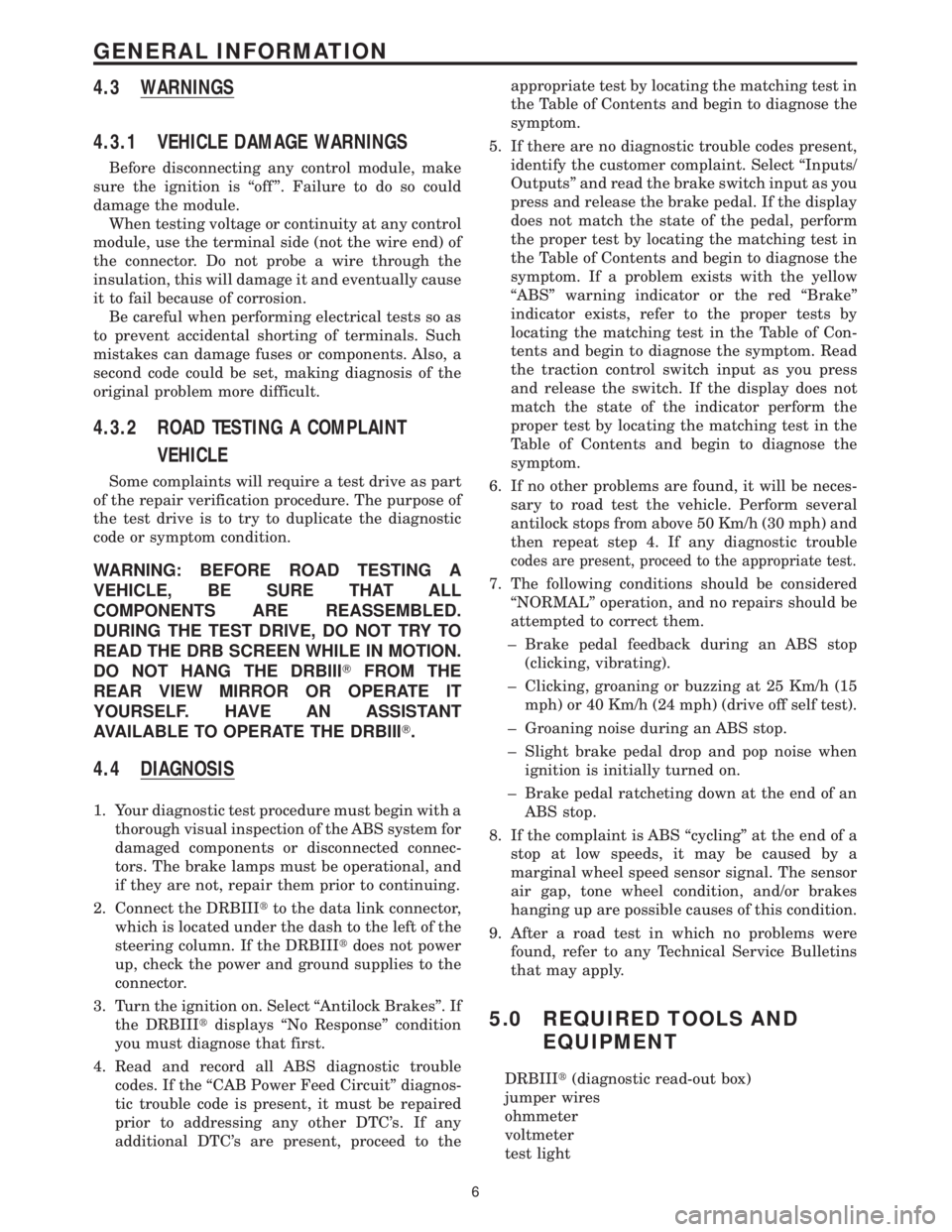
4.3 WARNINGS
4.3.1 VEHICLE DAMAGE WARNINGS
Before disconnecting any control module, make
sure the ignition is ``off ''. Failure to do so could
damage the module.
When testing voltage or continuity at any control
module, use the terminal side (not the wire end) of
the connector. Do not probe a wire through the
insulation, this will damage it and eventually cause
it to fail because of corrosion.
Be careful when performing electrical tests so as
to prevent accidental shorting of terminals. Such
mistakes can damage fuses or components. Also, a
second code could be set, making diagnosis of the
original problem more difficult.
4.3.2 ROAD TESTING A COMPLAINT
VEHICLE
Some complaints will require a test drive as part
of the repair verification procedure. The purpose of
the test drive is to try to duplicate the diagnostic
code or symptom condition.
WARNING: BEFORE ROAD TESTING A
VEHICLE, BE SURE THAT ALL
COMPONENTS ARE REASSEMBLED.
DURING THE TEST DRIVE, DO NOT TRY TO
READ THE DRB SCREEN WHILE IN MOTION.
DO NOT HANG THE DRBIIITFROM THE
REAR VIEW MIRROR OR OPERATE IT
YOURSELF. HAVE AN ASSISTANT
AVAILABLE TO OPERATE THE DRBIIIT.
4.4 DIAGNOSIS
1. Your diagnostic test procedure must begin with a
thorough visual inspection of the ABS system for
damaged components or disconnected connec-
tors. The brake lamps must be operational, and
if they are not, repair them prior to continuing.
2. Connect the DRBIIItto the data link connector,
which is located under the dash to the left of the
steering column. If the DRBIIItdoes not power
up, check the power and ground supplies to the
connector.
3. Turn the ignition on. Select ªAntilock Brakesº. If
the DRBIIItdisplays ªNo Responseº condition
you must diagnose that first.
4. Read and record all ABS diagnostic trouble
codes. If the ªCAB Power Feed Circuitº diagnos-
tic trouble code is present, it must be repaired
prior to addressing any other DTC's. If any
additional DTC's are present, proceed to theappropriate test by locating the matching test in
the Table of Contents and begin to diagnose the
symptom.
5. If there are no diagnostic trouble codes present,
identify the customer complaint. Select ªInputs/
Outputsº and read the brake switch input as you
press and release the brake pedal. If the display
does not match the state of the pedal, perform
the proper test by locating the matching test in
the Table of Contents and begin to diagnose the
symptom. If a problem exists with the yellow
ªABSº warning indicator or the red ªBrakeº
indicator exists, refer to the proper tests by
locating the matching test in the Table of Con-
tents and begin to diagnose the symptom. Read
the traction control switch input as you press
and release the switch. If the display does not
match the state of the indicator perform the
proper test by locating the matching test in the
Table of Contents and begin to diagnose the
symptom.
6. If no other problems are found, it will be neces-
sary to road test the vehicle. Perform several
antilock stops from above 50 Km/h (30 mph) and
then repeat step 4. If any diagnostic trouble
codes are present, proceed to the appropriate test.
7. The following conditions should be considered
ªNORMALº operation, and no repairs should be
attempted to correct them.
± Brake pedal feedback during an ABS stop
(clicking, vibrating).
± Clicking, groaning or buzzing at 25 Km/h (15
mph) or 40 Km/h (24 mph) (drive off self test).
± Groaning noise during an ABS stop.
± Slight brake pedal drop and pop noise when
ignition is initially turned on.
± Brake pedal ratcheting down at the end of an
ABS stop.
8. If the complaint is ABS ªcyclingº at the end of a
stop at low speeds, it may be caused by a
marginal wheel speed sensor signal. The sensor
air gap, tone wheel condition, and/or brakes
hanging up are possible causes of this condition.
9. After a road test in which no problems were
found, refer to any Technical Service Bulletins
that may apply.
5.0 REQUIRED TOOLS AND
EQUIPMENT
DRBIIIt(diagnostic read-out box)
jumper wires
ohmmeter
voltmeter
test light
6
GENERAL INFORMATION