ECO mode CHRYSLER VOYAGER 2001 User Guide
[x] Cancel search | Manufacturer: CHRYSLER, Model Year: 2001, Model line: VOYAGER, Model: CHRYSLER VOYAGER 2001Pages: 4284, PDF Size: 83.53 MB
Page 260 of 4284
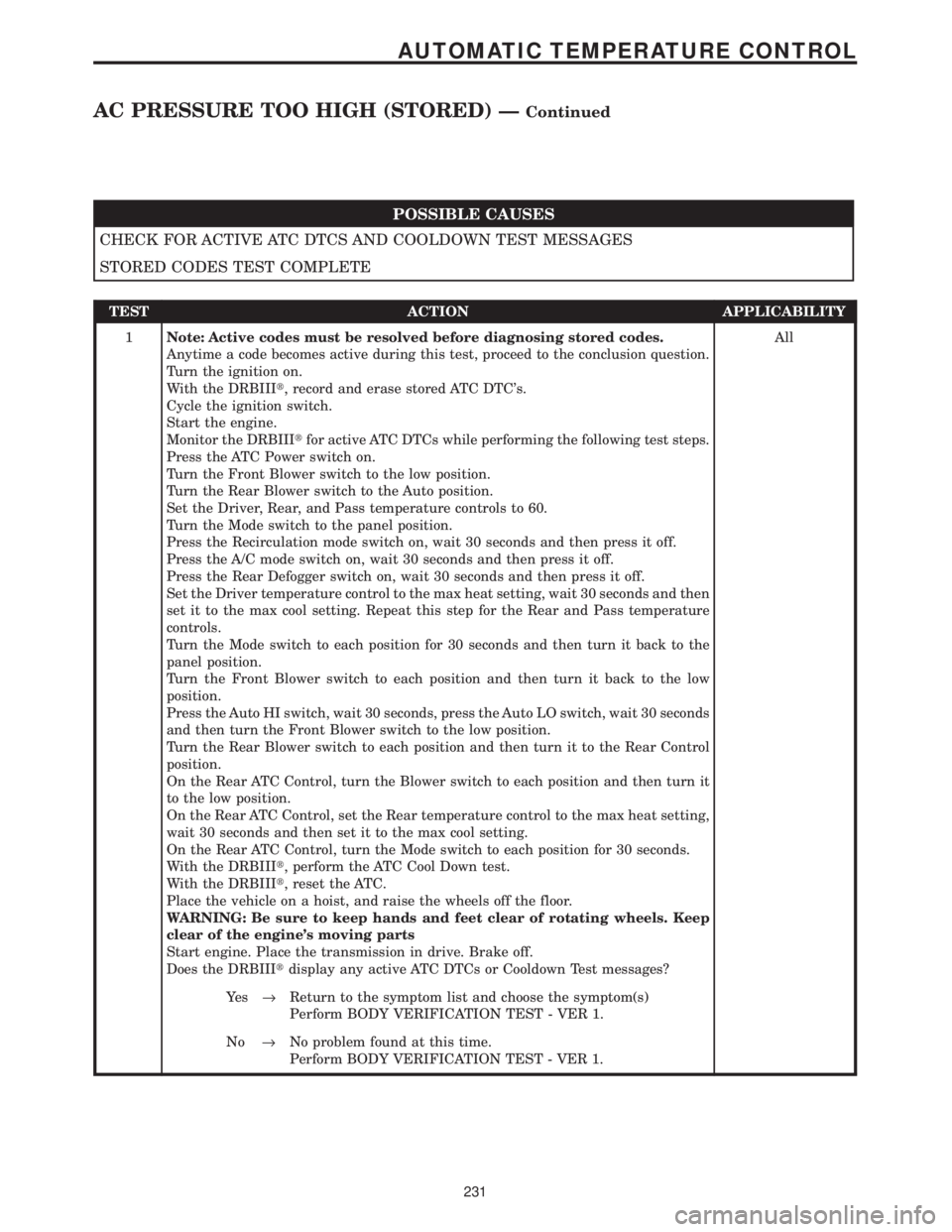
POSSIBLE CAUSES
CHECK FOR ACTIVE ATC DTCS AND COOLDOWN TEST MESSAGES
STORED CODES TEST COMPLETE
TEST ACTION APPLICABILITY
1Note: Active codes must be resolved before diagnosing stored codes.
Anytime a code becomes active during this test, proceed to the conclusion question.
Turn the ignition on.
With the DRBIIIt, record and erase stored ATC DTC's.
Cycle the ignition switch.
Start the engine.
Monitor the DRBIIItfor active ATC DTCs while performing the following test steps.
Press the ATC Power switch on.
Turn the Front Blower switch to the low position.
Turn the Rear Blower switch to the Auto position.
Set the Driver, Rear, and Pass temperature controls to 60.
Turn the Mode switch to the panel position.
Press the Recirculation mode switch on, wait 30 seconds and then press it off.
Press the A/C mode switch on, wait 30 seconds and then press it off.
Press the Rear Defogger switch on, wait 30 seconds and then press it off.
Set the Driver temperature control to the max heat setting, wait 30 seconds and then
set it to the max cool setting. Repeat this step for the Rear and Pass temperature
controls.
Turn the Mode switch to each position for 30 seconds and then turn it back to the
panel position.
Turn the Front Blower switch to each position and then turn it back to the low
position.
Press the Auto HI switch, wait 30 seconds, press the Auto LO switch, wait 30 seconds
and then turn the Front Blower switch to the low position.
Turn the Rear Blower switch to each position and then turn it to the Rear Control
position.
On the Rear ATC Control, turn the Blower switch to each position and then turn it
to the low position.
On the Rear ATC Control, set the Rear temperature control to the max heat setting,
wait 30 seconds and then set it to the max cool setting.
On the Rear ATC Control, turn the Mode switch to each position for 30 seconds.
With the DRBIIIt, perform the ATC Cool Down test.
With the DRBIIIt, reset the ATC.
Place the vehicle on a hoist, and raise the wheels off the floor.
WARNING: Be sure to keep hands and feet clear of rotating wheels. Keep
clear of the engine's moving parts
Start engine. Place the transmission in drive. Brake off.
Does the DRBIIItdisplay any active ATC DTCs or Cooldown Test messages?All
Ye s®Return to the symptom list and choose the symptom(s)
Perform BODY VERIFICATION TEST - VER 1.
No®No problem found at this time.
Perform BODY VERIFICATION TEST - VER 1.
231
AUTOMATIC TEMPERATURE CONTROL
AC PRESSURE TOO HIGH (STORED) ÐContinued
Page 281 of 4284
Symptom:
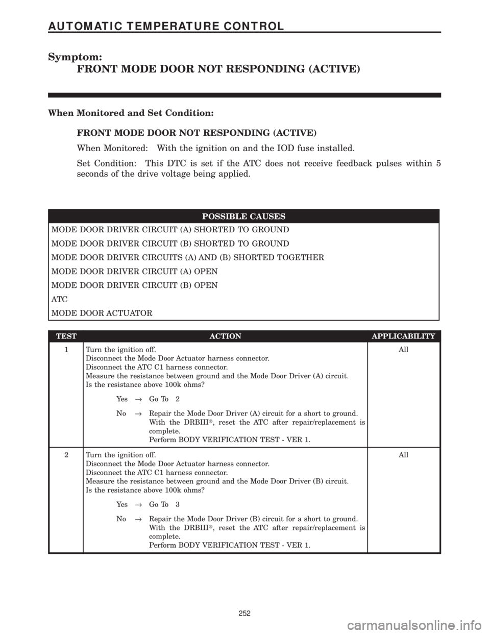
FRONT MODE DOOR NOT RESPONDING (ACTIVE)
When Monitored and Set Condition:
FRONT MODE DOOR NOT RESPONDING (ACTIVE)
When Monitored: With the ignition on and the IOD fuse installed.
Set Condition: This DTC is set if the ATC does not receive feedback pulses within 5
seconds of the drive voltage being applied.
POSSIBLE CAUSES
MODE DOOR DRIVER CIRCUIT (A) SHORTED TO GROUND
MODE DOOR DRIVER CIRCUIT (B) SHORTED TO GROUND
MODE DOOR DRIVER CIRCUITS (A) AND (B) SHORTED TOGETHER
MODE DOOR DRIVER CIRCUIT (A) OPEN
MODE DOOR DRIVER CIRCUIT (B) OPEN
AT C
MODE DOOR ACTUATOR
TEST ACTION APPLICABILITY
1 Turn the ignition off.
Disconnect the Mode Door Actuator harness connector.
Disconnect the ATC C1 harness connector.
Measure the resistance between ground and the Mode Door Driver (A) circuit.
Is the resistance above 100k ohms?All
Ye s®Go To 2
No®Repair the Mode Door Driver (A) circuit for a short to ground.
With the DRBIIIt, reset the ATC after repair/replacement is
complete.
Perform BODY VERIFICATION TEST - VER 1.
2 Turn the ignition off.
Disconnect the Mode Door Actuator harness connector.
Disconnect the ATC C1 harness connector.
Measure the resistance between ground and the Mode Door Driver (B) circuit.
Is the resistance above 100k ohms?All
Ye s®Go To 3
No®Repair the Mode Door Driver (B) circuit for a short to ground.
With the DRBIIIt, reset the ATC after repair/replacement is
complete.
Perform BODY VERIFICATION TEST - VER 1.
252
AUTOMATIC TEMPERATURE CONTROL
Page 285 of 4284
Symptom:
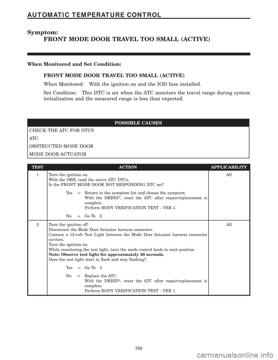
FRONT MODE DOOR TRAVEL TOO SMALL (ACTIVE)
When Monitored and Set Condition:
FRONT MODE DOOR TRAVEL TOO SMALL (ACTIVE)
When Monitored: With the ignition on and the IOD fuse installed.
Set Condition: This DTC is set when the ATC monitors the travel range during system
initialization and the measured range is less than expected.
POSSIBLE CAUSES
CHECK THE ATC FOR DTCS
AT C
OBSTRUCTED MODE DOOR
MODE DOOR ACTUATOR
TEST ACTION APPLICABILITY
1 Turn the ignition on.
With the DRB, read the active ATC DTCs.
Is the FRONT MODE DOOR NOT RESPONDING DTC set?All
Ye s®Return to the symptom list and choose the symptom.
With the DRBIIIt, reset the ATC after repair/replacement is
complete.
Perform BODY VERIFICATION TEST - VER 1.
No®Go To 2
2 Turn the ignition off.
Disconnect the Mode Door Actuator harness connector.
Connect a 12-volt Test Light between the Mode Door Actuator harness connector
cavities.
Turn the ignition on.
While monitoring the test light, turn the mode control knob in each position.
Note: Observe test light for approximately 30 seconds.
Does the test light start to flash and stay flashing?All
Ye s®Go To 3
No®Replace the ATC.
With the DRBIIIt, reset the ATC after repair/replacement is
complete.
Perform BODY VERIFICATION TEST - VER 1.
256
AUTOMATIC TEMPERATURE CONTROL
Page 313 of 4284
Symptom:
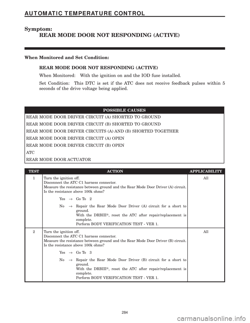
REAR MODE DOOR NOT RESPONDING (ACTIVE)
When Monitored and Set Condition:
REAR MODE DOOR NOT RESPONDING (ACTIVE)
When Monitored: With the ignition on and the IOD fuse installed.
Set Condition: This DTC is set if the ATC does not receive feedback pulses within 5
seconds of the drive voltage being applied.
POSSIBLE CAUSES
REAR MODE DOOR DRIVER CIRCUIT (A) SHORTED TO GROUND
REAR MODE DOOR DRIVER CIRCUIT (B) SHORTED TO GROUND
REAR MODE DOOR DRIVER CIRCUITS (A) AND (B) SHORTED TOGETHER
REAR MODE DOOR DRIVER CIRCUIT (A) OPEN
REAR MODE DOOR DRIVER CIRCUIT (B) OPEN
AT C
REAR MODE DOOR ACTUATOR
TEST ACTION APPLICABILITY
1 Turn the ignition off.
Disconnect the ATC C1 harness connector.
Measure the resistance between ground and the Rear Mode Door Driver (A) circuit.
Is the resistance above 100k ohms?All
Ye s®Go To 2
No®Repair the Rear Mode Door Driver (A) circuit for a short to
ground.
With the DRBIIIt, reset the ATC after repair/replacement is
complete.
Perform BODY VERIFICATION TEST - VER 1.
2 Turn the ignition off.
Disconnect the ATC C1 harness connector.
Measure the resistance between ground and the Rear Mode Door Driver (B) circuit.
Is the resistance above 100k ohms?All
Ye s®Go To 3
No®Repair the Rear Mode Door Driver (B) circuit for a short to
ground.
With the DRBIIIt, reset the ATC after repair/replacement is
complete.
Perform BODY VERIFICATION TEST - VER 1.
284
AUTOMATIC TEMPERATURE CONTROL
Page 317 of 4284
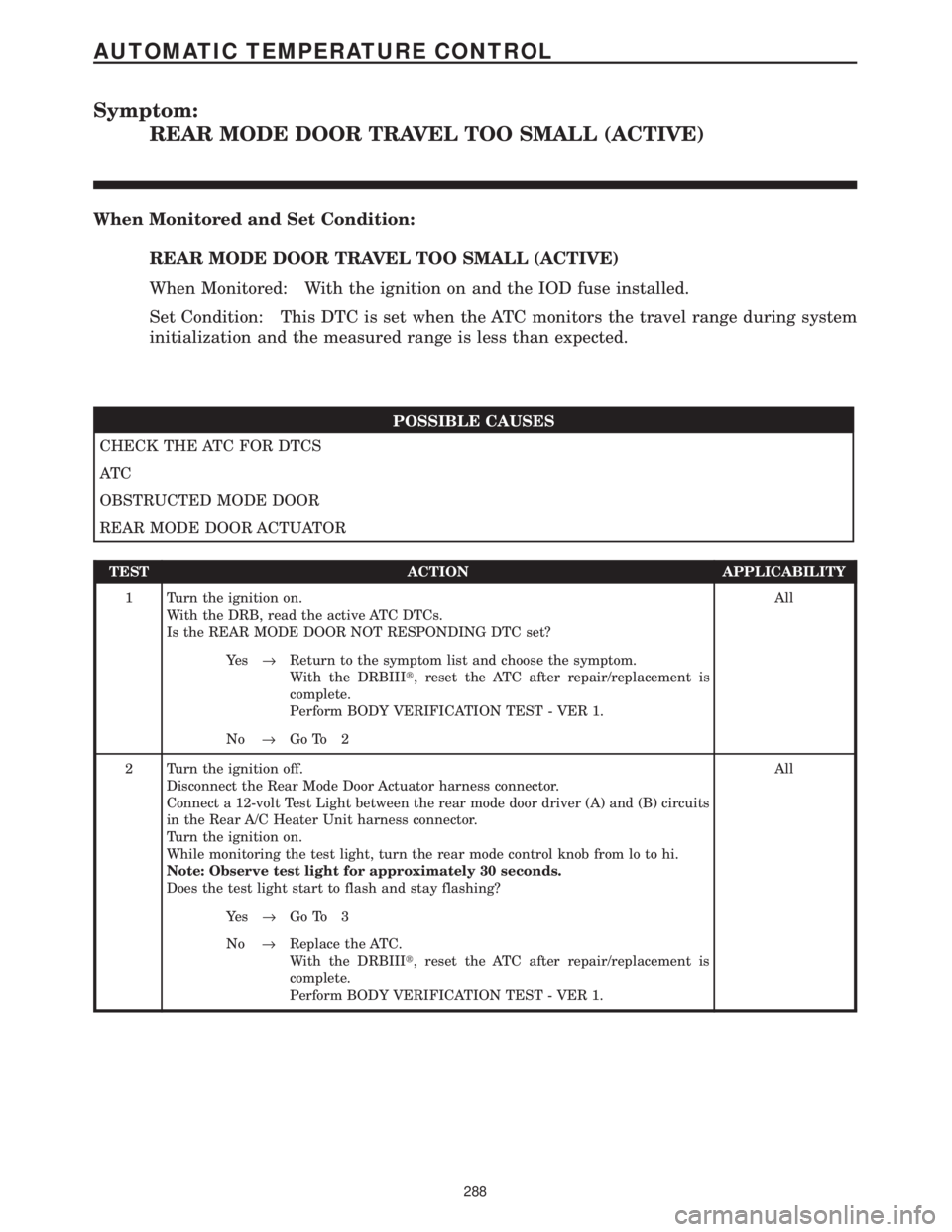
Symptom:
REAR MODE DOOR TRAVEL TOO SMALL (ACTIVE)
When Monitored and Set Condition:
REAR MODE DOOR TRAVEL TOO SMALL (ACTIVE)
When Monitored: With the ignition on and the IOD fuse installed.
Set Condition: This DTC is set when the ATC monitors the travel range during system
initialization and the measured range is less than expected.
POSSIBLE CAUSES
CHECK THE ATC FOR DTCS
AT C
OBSTRUCTED MODE DOOR
REAR MODE DOOR ACTUATOR
TEST ACTION APPLICABILITY
1 Turn the ignition on.
With the DRB, read the active ATC DTCs.
Is the REAR MODE DOOR NOT RESPONDING DTC set?All
Ye s®Return to the symptom list and choose the symptom.
With the DRBIIIt, reset the ATC after repair/replacement is
complete.
Perform BODY VERIFICATION TEST - VER 1.
No®Go To 2
2 Turn the ignition off.
Disconnect the Rear Mode Door Actuator harness connector.
Connect a 12-volt Test Light between the rear mode door driver (A) and (B) circuits
in the Rear A/C Heater Unit harness connector.
Turn the ignition on.
While monitoring the test light, turn the rear mode control knob from lo to hi.
Note: Observe test light for approximately 30 seconds.
Does the test light start to flash and stay flashing?All
Ye s®Go To 3
No®Replace the ATC.
With the DRBIIIt, reset the ATC after repair/replacement is
complete.
Perform BODY VERIFICATION TEST - VER 1.
288
AUTOMATIC TEMPERATURE CONTROL
Page 326 of 4284

TEST ACTION APPLICABILITY
2WARNING: DO NOT OPERATE THE DCHA IN AN ENCLOSED AREA SUCH
AS A GARAGE THAT DOES NOT HAVE EXHAUST VENTILATION FACILI-
TIES. ALWAYS VENT THE DCHA's EXHAUST WHEN OPERATING THE
DCHA. FAILURE TO FOLLOW THESE INSTRUCTIONS MAY RESULT IN
PERSONAL INJURY OR DEATH.
Turn the ignition on.
With the DRBIIIt, read Cabin Heater DTCs.
Is DTC B1813 Heater In Lockout Mode present?All
Ye s®Go To 3
No®Go To 4
3WARNING: DO NOT OPERATE THE DCHA IN AN ENCLOSED AREA SUCH
AS A GARAGE THAT DOES NOT HAVE EXHAUST VENTILATION FACILI-
TIES. ALWAYS VENT THE DCHA's EXHAUST WHEN OPERATING THE
DCHA. FAILURE TO FOLLOW THESE INSTRUCTIONS MAY RESULT IN
PERSONAL INJURY OR DEATH.
Start the engine.
Allow the engine to idle.
Turn the A/C - Heater Control Module's Power switch on.
Turn the Blower switch to the high speed position.
Set the Blend Control to the max heat position.
Remove Cabin Heater Fuse #15 from the IPM for a minimum of five seconds, then
reinstall the fuse. The DCHA may attempt to start.
Turn the Blower switch off and turn the A/C - Heater Control Module's Power switch
off.
Turn the engine off.
View repairAll
Repair
Go To 4
297
CABIN HEATER
CABIN HEATER PRE-TEST ÐContinued
Page 327 of 4284
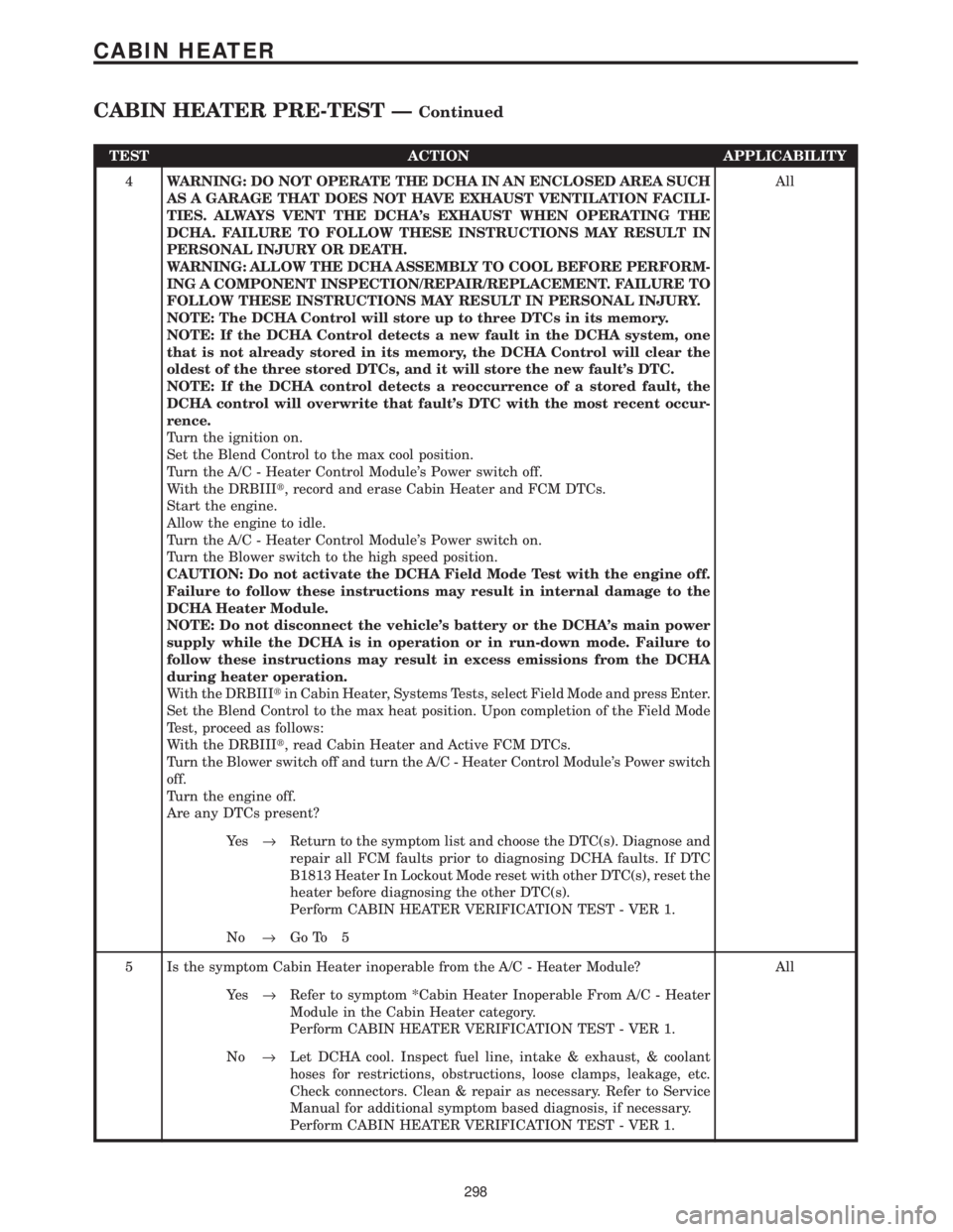
TEST ACTION APPLICABILITY
4WARNING: DO NOT OPERATE THE DCHA IN AN ENCLOSED AREA SUCH
AS A GARAGE THAT DOES NOT HAVE EXHAUST VENTILATION FACILI-
TIES. ALWAYS VENT THE DCHA's EXHAUST WHEN OPERATING THE
DCHA. FAILURE TO FOLLOW THESE INSTRUCTIONS MAY RESULT IN
PERSONAL INJURY OR DEATH.
WARNING: ALLOW THE DCHA ASSEMBLY TO COOL BEFORE PERFORM-
ING A COMPONENT INSPECTION/REPAIR/REPLACEMENT. FAILURE TO
FOLLOW THESE INSTRUCTIONS MAY RESULT IN PERSONAL INJURY.
NOTE: The DCHA Control will store up to three DTCs in its memory.
NOTE: If the DCHA Control detects a new fault in the DCHA system, one
that is not already stored in its memory, the DCHA Control will clear the
oldest of the three stored DTCs, and it will store the new fault's DTC.
NOTE: If the DCHA control detects a reoccurrence of a stored fault, the
DCHA control will overwrite that fault's DTC with the most recent occur-
rence.
Turn the ignition on.
Set the Blend Control to the max cool position.
Turn the A/C - Heater Control Module's Power switch off.
With the DRBIIIt, record and erase Cabin Heater and FCM DTCs.
Start the engine.
Allow the engine to idle.
Turn the A/C - Heater Control Module's Power switch on.
Turn the Blower switch to the high speed position.
CAUTION: Do not activate the DCHA Field Mode Test with the engine off.
Failure to follow these instructions may result in internal damage to the
DCHA Heater Module.
NOTE: Do not disconnect the vehicle's battery or the DCHA's main power
supply while the DCHA is in operation or in run-down mode. Failure to
follow these instructions may result in excess emissions from the DCHA
during heater operation.
With the DRBIIItin Cabin Heater, Systems Tests, select Field Mode and press Enter.
Set the Blend Control to the max heat position. Upon completion of the Field Mode
Test, proceed as follows:
With the DRBIIIt, read Cabin Heater and Active FCM DTCs.
Turn the Blower switch off and turn the A/C - Heater Control Module's Power switch
off.
Turn the engine off.
Are any DTCs present?All
Ye s®Return to the symptom list and choose the DTC(s). Diagnose and
repair all FCM faults prior to diagnosing DCHA faults. If DTC
B1813 Heater In Lockout Mode reset with other DTC(s), reset the
heater before diagnosing the other DTC(s).
Perform CABIN HEATER VERIFICATION TEST - VER 1.
No®Go To 5
5 Is the symptom Cabin Heater inoperable from the A/C - Heater Module? All
Ye s®Refer to symptom *Cabin Heater Inoperable From A/C - Heater
Module in the Cabin Heater category.
Perform CABIN HEATER VERIFICATION TEST - VER 1.
No®Let DCHA cool. Inspect fuel line, intake & exhaust, & coolant
hoses for restrictions, obstructions, loose clamps, leakage, etc.
Check connectors. Clean & repair as necessary. Refer to Service
Manual for additional symptom based diagnosis, if necessary.
Perform CABIN HEATER VERIFICATION TEST - VER 1.
298
CABIN HEATER
CABIN HEATER PRE-TEST ÐContinued
Page 333 of 4284

Symptom:
B1802 POWER SUPPLY OUT OF RANGE: LOW VOLTAGE THRESH-
OLD
When Monitored and Set Condition:
B1802 POWER SUPPLY OUT OF RANGE: LOW VOLTAGE THRESHOLD
When Monitored: With the engine running.
Set Condition: This DTC will set if the DCHA's power supply voltage drops below 10.0
volts for longer than 20 seconds.
POSSIBLE CAUSES
FIELD MODE TEST RUN WITH THE ENGINE OFF
VEHICLE'S BATTERY SYSTEM
VEHICLE'S CHARGING SYSTEM NOT OPERATING PROPERLY
DCHA CONTROL UNIT FAULT
FUSED B+ CIRCUIT HIGH RESISTANCE
DCHA CONTROL UNIT FAULT
TEST ACTION APPLICABILITY
1WARNING: DO NOT OPERATE THE DCHA IN AN ENCLOSED AREA SUCH
AS A GARAGE THAT DOES NOT HAVE EXHAUST VENTILATION FACILI-
TIES. ALWAYS VENT THE DCHA's EXHAUST WHEN OPERATING THE
DCHA. FAILURE TO FOLLOW THESE INSTRUCTIONS MAY RESULT IN
PERSONAL INJURY OR DEATH.
CAUTION: DO NOT PERFORM THIS TEST UNLESS DIRECTED HERE BY
THE CABIN HEATER PRE-TEST. ALWAYS PERFORM THE CABIN HEATER
PRE-TEST PRIOR TO PERFORMING ANY OTHER CABIN HEATER TEST
FOR THE RESULT TO BE VALID.
Was the Field Mode Test run with the engine off?All
Ye s®Rerun the Field Mode Test exactly as it is described in Test 4 of
the Cabin Heater Pre-Test. If DTC B1802 resets, Go To Test #2 of
this symptom. Otherwise, perform other diagnosis and testing as
necessary.
Perform CABIN HEATER VERIFICATION TEST - VER 1.
No®Go To 2
304
CABIN HEATER
Page 342 of 4284

Symptom:
B1813 HEATER IN LOCKOUT MODE
When Monitored and Set Condition:
B1813 HEATER IN LOCKOUT MODE
When Monitored: During DCHA activation.
Set Condition: This DTC will set if six continuous attempts to start heater operation fail
due to one or more faults in the DCHA system.
POSSIBLE CAUSES
B1813 AND ADDITIONAL DTC(S) PRESENT
B1813 RESET, NO ADDITIONAL DTC(S) PRESENT
B1813 CLEARED, ADDITIONAL DTC(S) PRESENT
STORED DCHA DTC(S) TEST COMPLETE
TEST ACTION APPLICABILITY
1WARNING: DO NOT OPERATE THE DCHA IN AN ENCLOSED AREA SUCH
AS A GARAGE THAT DOES NOT HAVE EXHAUST VENTILATION FACILI-
TIES. ALWAYS VENT THE DCHA's EXHAUST WHEN OPERATING THE
DCHA. FAILURE TO FOLLOW THESE INSTRUCTIONS MAY RESULT IN
PERSONAL INJURY OR DEATH.
Start the engine.
Allow the engine to idle.
Turn the A/C - Heater Control Module's Power switch on.
Turn the Blower Switch to the high speed position.
Set the Blend Control to the max heat position.
Remove Cabin Heater Fuse #15 from the IPM for a minimum of five seconds, then
reinstall the fuse. The DCHA may attempt to start.
Turn the Blower switch off and turn the A/C - Heater Control Module's Power switch
off.
Turn the engine off.
View repairAll
Repair
Go To 2
313
CABIN HEATER
Page 343 of 4284
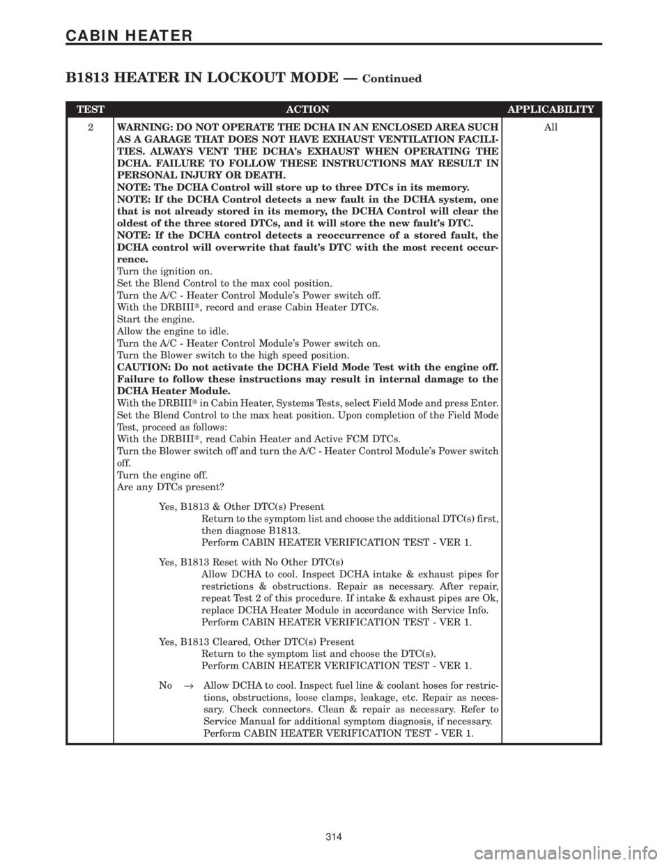
TEST ACTION APPLICABILITY
2WARNING: DO NOT OPERATE THE DCHA IN AN ENCLOSED AREA SUCH
AS A GARAGE THAT DOES NOT HAVE EXHAUST VENTILATION FACILI-
TIES. ALWAYS VENT THE DCHA's EXHAUST WHEN OPERATING THE
DCHA. FAILURE TO FOLLOW THESE INSTRUCTIONS MAY RESULT IN
PERSONAL INJURY OR DEATH.
NOTE: The DCHA Control will store up to three DTCs in its memory.
NOTE: If the DCHA Control detects a new fault in the DCHA system, one
that is not already stored in its memory, the DCHA Control will clear the
oldest of the three stored DTCs, and it will store the new fault's DTC.
NOTE: If the DCHA control detects a reoccurrence of a stored fault, the
DCHA control will overwrite that fault's DTC with the most recent occur-
rence.
Turn the ignition on.
Set the Blend Control to the max cool position.
Turn the A/C - Heater Control Module's Power switch off.
With the DRBIIIt, record and erase Cabin Heater DTCs.
Start the engine.
Allow the engine to idle.
Turn the A/C - Heater Control Module's Power switch on.
Turn the Blower switch to the high speed position.
CAUTION: Do not activate the DCHA Field Mode Test with the engine off.
Failure to follow these instructions may result in internal damage to the
DCHA Heater Module.
With the DRBIIItin Cabin Heater, Systems Tests, select Field Mode and press Enter.
Set the Blend Control to the max heat position. Upon completion of the Field Mode
Test, proceed as follows:
With the DRBIIIt, read Cabin Heater and Active FCM DTCs.
Turn the Blower switch off and turn the A/C - Heater Control Module's Power switch
off.
Turn the engine off.
Are any DTCs present?All
Yes, B1813 & Other DTC(s) Present
Return to the symptom list and choose the additional DTC(s) first,
then diagnose B1813.
Perform CABIN HEATER VERIFICATION TEST - VER 1.
Yes, B1813 Reset with No Other DTC(s)
Allow DCHA to cool. Inspect DCHA intake & exhaust pipes for
restrictions & obstructions. Repair as necessary. After repair,
repeat Test 2 of this procedure. If intake & exhaust pipes are Ok,
replace DCHA Heater Module in accordance with Service Info.
Perform CABIN HEATER VERIFICATION TEST - VER 1.
Yes, B1813 Cleared, Other DTC(s) Present
Return to the symptom list and choose the DTC(s).
Perform CABIN HEATER VERIFICATION TEST - VER 1.
No®Allow DCHA to cool. Inspect fuel line & coolant hoses for restric-
tions, obstructions, loose clamps, leakage, etc. Repair as neces-
sary. Check connectors. Clean & repair as necessary. Refer to
Service Manual for additional symptom diagnosis, if necessary.
Perform CABIN HEATER VERIFICATION TEST - VER 1.
314
CABIN HEATER
B1813 HEATER IN LOCKOUT MODE ÐContinued