check engine CHRYSLER VOYAGER 2001 User Guide
[x] Cancel search | Manufacturer: CHRYSLER, Model Year: 2001, Model line: VOYAGER, Model: CHRYSLER VOYAGER 2001Pages: 4284, PDF Size: 83.53 MB
Page 287 of 4284

Symptom:
INVALID CONDITIONS FOR COOLDOWN TEST, EVAP TEMPERA-
TURE TOO LOW
When Monitored and Set Condition:
INVALID CONDITIONS FOR COOLDOWN TEST, EVAP TEMPERATURE TOO
LOW
When Monitored: When executing the Cooldown Test.
Set Condition: This message will be displayed if the A/C - Heater Control Module sees
evaporator temperature below 12.7ÉC (55ÉF) when executing the Cooldown Test.
POSSIBLE CAUSES
EVAPORATOR TEMPERATURE TOO LOW
ATC DTC(S) PRESENT
CHECK THE PCM/ECM FOR DTCS
EVAPORATOR TEMPERATURE SENSOR
SENSOR GROUND CIRCUIT HIGH RESISTANCE
EVAPORATOR TEMPERATURE SENSOR SIGNAL CIRCUIT HIGH RESISTANCE
AUTOMATIC TEMPERATURE CONTROL
TEST ACTION APPLICABILITY
1CAUTION: The work area ambient temperature must be above 15.6ÉC (60ÉF)
to test A/C system operation.
Start the engine.
Turn the A/C off.
Turn the Blower on high. Allow the blower to run for 5 minutes to ensure that the
Evaporator Temperature Sensor temperature is above 12.7ÉC (55ÉF).
With the DRBIIIt, actuate the Cooldown Test.
Does the DRBIIItdisplay: Cooldown Test Too Cold To Start?All
Ye s®Go To 2
No®Perform additional testing as necessary.
Perform BODY VERIFICATION TEST - VER 1.
2CAUTION: The work area ambient temperature must be above 15.6ÉC (60ÉF)
to test A/C system operation.
Turn the ignition on.
With the DRBIIIt, read ATC DTCs.
Does the DRBIIItdisplay any ATC DTCs?All
Ye s®Return to the symptom list and choose the symptom(s). After the
repair is complete, with the DRBIIIt, erase the DTC(s). Cycle the
ignition switch. With the DRBIIIt, reset the ATC. With the
DRBIIIt, actuate the Cooldown Test.
Perform BODY VERIFICATION TEST - VER 1.
No®Go To 3
258
AUTOMATIC TEMPERATURE CONTROL
Page 327 of 4284
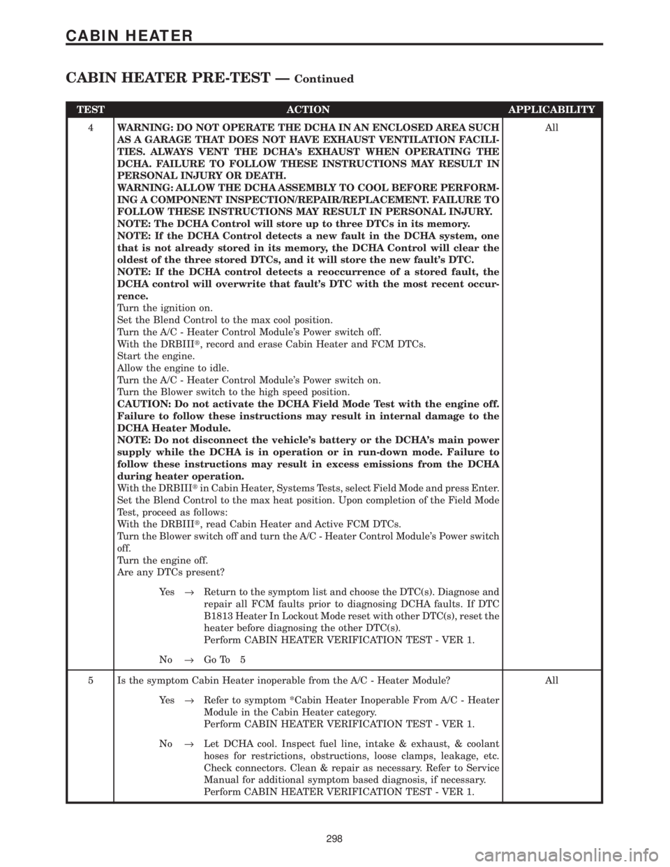
TEST ACTION APPLICABILITY
4WARNING: DO NOT OPERATE THE DCHA IN AN ENCLOSED AREA SUCH
AS A GARAGE THAT DOES NOT HAVE EXHAUST VENTILATION FACILI-
TIES. ALWAYS VENT THE DCHA's EXHAUST WHEN OPERATING THE
DCHA. FAILURE TO FOLLOW THESE INSTRUCTIONS MAY RESULT IN
PERSONAL INJURY OR DEATH.
WARNING: ALLOW THE DCHA ASSEMBLY TO COOL BEFORE PERFORM-
ING A COMPONENT INSPECTION/REPAIR/REPLACEMENT. FAILURE TO
FOLLOW THESE INSTRUCTIONS MAY RESULT IN PERSONAL INJURY.
NOTE: The DCHA Control will store up to three DTCs in its memory.
NOTE: If the DCHA Control detects a new fault in the DCHA system, one
that is not already stored in its memory, the DCHA Control will clear the
oldest of the three stored DTCs, and it will store the new fault's DTC.
NOTE: If the DCHA control detects a reoccurrence of a stored fault, the
DCHA control will overwrite that fault's DTC with the most recent occur-
rence.
Turn the ignition on.
Set the Blend Control to the max cool position.
Turn the A/C - Heater Control Module's Power switch off.
With the DRBIIIt, record and erase Cabin Heater and FCM DTCs.
Start the engine.
Allow the engine to idle.
Turn the A/C - Heater Control Module's Power switch on.
Turn the Blower switch to the high speed position.
CAUTION: Do not activate the DCHA Field Mode Test with the engine off.
Failure to follow these instructions may result in internal damage to the
DCHA Heater Module.
NOTE: Do not disconnect the vehicle's battery or the DCHA's main power
supply while the DCHA is in operation or in run-down mode. Failure to
follow these instructions may result in excess emissions from the DCHA
during heater operation.
With the DRBIIItin Cabin Heater, Systems Tests, select Field Mode and press Enter.
Set the Blend Control to the max heat position. Upon completion of the Field Mode
Test, proceed as follows:
With the DRBIIIt, read Cabin Heater and Active FCM DTCs.
Turn the Blower switch off and turn the A/C - Heater Control Module's Power switch
off.
Turn the engine off.
Are any DTCs present?All
Ye s®Return to the symptom list and choose the DTC(s). Diagnose and
repair all FCM faults prior to diagnosing DCHA faults. If DTC
B1813 Heater In Lockout Mode reset with other DTC(s), reset the
heater before diagnosing the other DTC(s).
Perform CABIN HEATER VERIFICATION TEST - VER 1.
No®Go To 5
5 Is the symptom Cabin Heater inoperable from the A/C - Heater Module? All
Ye s®Refer to symptom *Cabin Heater Inoperable From A/C - Heater
Module in the Cabin Heater category.
Perform CABIN HEATER VERIFICATION TEST - VER 1.
No®Let DCHA cool. Inspect fuel line, intake & exhaust, & coolant
hoses for restrictions, obstructions, loose clamps, leakage, etc.
Check connectors. Clean & repair as necessary. Refer to Service
Manual for additional symptom based diagnosis, if necessary.
Perform CABIN HEATER VERIFICATION TEST - VER 1.
298
CABIN HEATER
CABIN HEATER PRE-TEST ÐContinued
Page 336 of 4284

Symptom:
B1802 POWER SUPPLY OUT OF RANGE: VOLTAGE ABOVE 15.5
VOLTS
When Monitored and Set Condition:
B1802 POWER SUPPLY OUT OF RANGE: VOLTAGE ABOVE 15.5 VOLTS
When Monitored: With the engine running.
Set Condition: This DTC will set if the DCHA's power supply voltage exceeds 15.5 volts
for longer than six seconds.
POSSIBLE CAUSES
VEHICLE'S CHARGING SYSTEM OVERCHARGING
DCHA CONTROL UNIT FAULT
TEST ACTION APPLICABILITY
1WARNING: DO NOT OPERATE THE DCHA IN AN ENCLOSED AREA SUCH
AS A GARAGE THAT DOES NOT HAVE EXHAUST VENTILATION FACILI-
TIES. ALWAYS VENT THE DCHA's EXHAUST WHEN OPERATING THE
DCHA. FAILURE TO FOLLOW THESE INSTRUCTIONS MAY RESULT IN
PERSONAL INJURY OR DEATH.
WARNING: ALLOW THE DCHA ASSEMBLY TO COOL BEFORE PERFORM-
ING A COMPONENT INSPECTION/REPAIR/REPLACEMENT. FAILURE TO
FOLLOW THESE INSTRUCTIONS MAY RESULT IN PERSONAL INJURY.
CAUTION: DO NOT PERFORM THIS TEST UNLESS DIRECTED HERE BY
THE CABIN HEATER PRE-TEST. ALWAYS PERFORM THE CABIN HEATER
PRE-TEST PRIOR TO PERFORMING ANY OTHER CABIN HEATER TEST
FOR THE RESULT TO BE VALID.
Check the vehicle's charging system for proper operation in accordance with the
Service Information.
Is the vehicle's charging system operating properly?All
Ye s®Replace the DCHA Heater Module in accordance with the Service
Information.
Perform CABIN HEATER VERIFICATION TEST - VER 1.
No®Repair the vehicle's charging system in accordance with the
Service Information.
Perform CABIN HEATER VERIFICATION TEST - VER 1.
307
CABIN HEATER
Page 338 of 4284
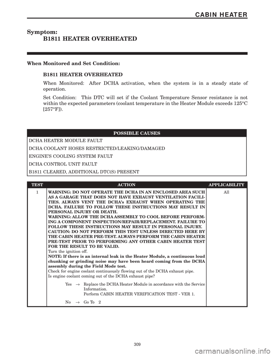
Symptom:
B1811 HEATER OVERHEATED
When Monitored and Set Condition:
B1811 HEATER OVERHEATED
When Monitored: After DCHA activation, when the system is in a steady state of
operation.
Set Condition: This DTC will set if the Coolant Temperature Sensor resistance is not
within the expected parameters (coolant temperature in the Heater Module exceeds 125ÉC
[257ÉF]).
POSSIBLE CAUSES
DCHA HEATER MODULE FAULT
DCHA COOLANT HOSES RESTRICTED/LEAKING/DAMAGED
ENGINE'S COOLING SYSTEM FAULT
DCHA CONTROL UNIT FAULT
B1811 CLEARED, ADDITIONAL DTC(S) PRESENT
TEST ACTION APPLICABILITY
1WARNING: DO NOT OPERATE THE DCHA IN AN ENCLOSED AREA SUCH
AS A GARAGE THAT DOES NOT HAVE EXHAUST VENTILATION FACILI-
TIES. ALWAYS VENT THE DCHA's EXHAUST WHEN OPERATING THE
DCHA. FAILURE TO FOLLOW THESE INSTRUCTIONS MAY RESULT IN
PERSONAL INJURY OR DEATH.
WARNING: ALLOW THE DCHA ASSEMBLY TO COOL BEFORE PERFORM-
ING A COMPONENT INSPECTION/REPAIR/REPLACEMENT. FAILURE TO
FOLLOW THESE INSTRUCTIONS MAY RESULT IN PERSONAL INJURY.
CAUTION: DO NOT PERFORM THIS TEST UNLESS DIRECTED HERE BY
THE CABIN HEATER PRE-TEST. ALWAYS PERFORM THE CABIN HEATER
PRE-TEST PRIOR TO PERFORMING ANY OTHER CABIN HEATER TEST
FOR THE RESULT TO BE VALID.
Turn the ignition off.
NOTE: If there is an internal leak in the Heater Module, a continuous loud
chunking or grinding noise may have been heard coming from the DCHA
assembly during the Field Mode test.
Check for engine coolant continuously flowing out of the DCHA exhaust pipe.
Is engine coolant coming out of the DCHA exhaust pipe?All
Ye s®Replace the DCHA Heater Module in accordance with the Service
Information.
Perform CABIN HEATER VERIFICATION TEST - VER 1.
No®Go To 2
309
CABIN HEATER
Page 339 of 4284
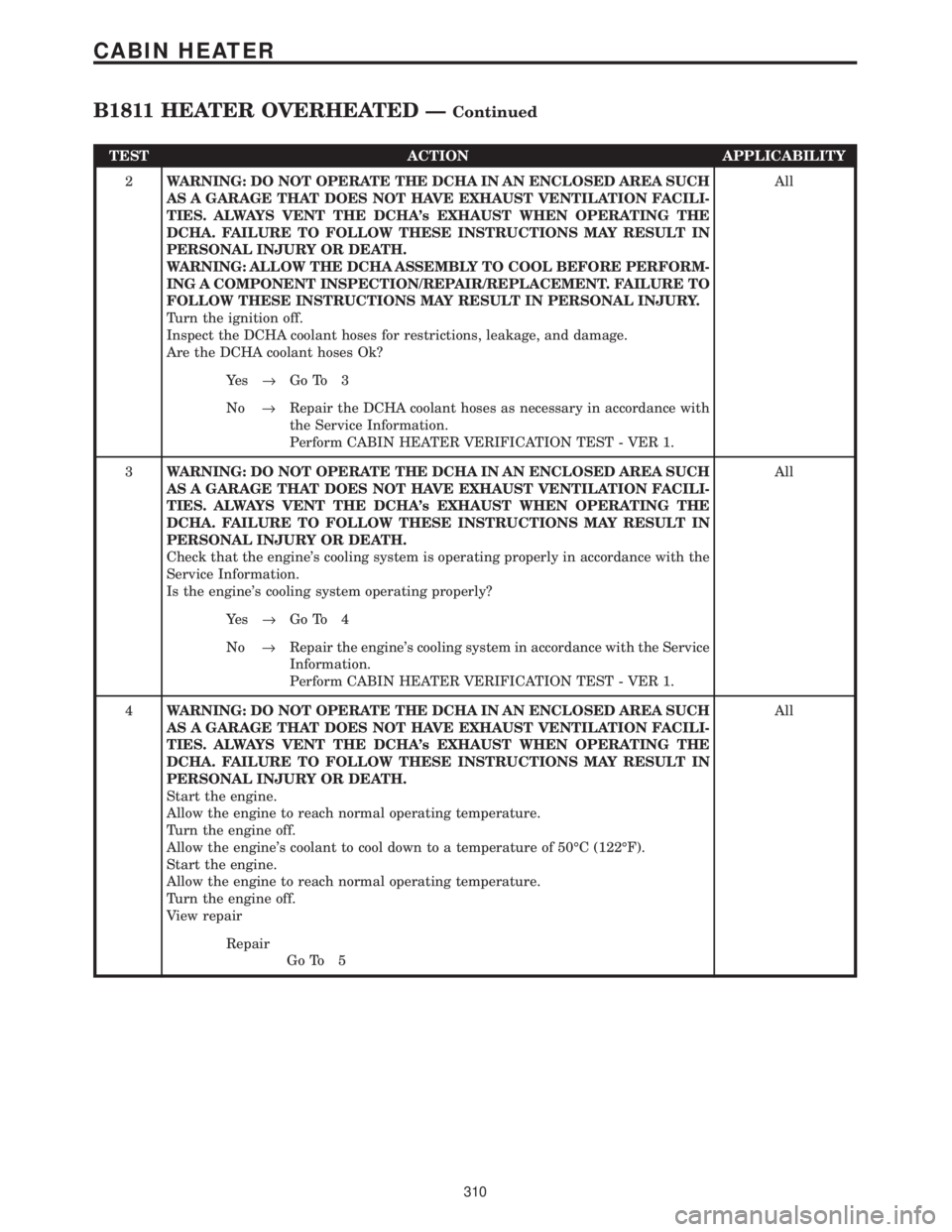
TEST ACTION APPLICABILITY
2WARNING: DO NOT OPERATE THE DCHA IN AN ENCLOSED AREA SUCH
AS A GARAGE THAT DOES NOT HAVE EXHAUST VENTILATION FACILI-
TIES. ALWAYS VENT THE DCHA's EXHAUST WHEN OPERATING THE
DCHA. FAILURE TO FOLLOW THESE INSTRUCTIONS MAY RESULT IN
PERSONAL INJURY OR DEATH.
WARNING: ALLOW THE DCHA ASSEMBLY TO COOL BEFORE PERFORM-
ING A COMPONENT INSPECTION/REPAIR/REPLACEMENT. FAILURE TO
FOLLOW THESE INSTRUCTIONS MAY RESULT IN PERSONAL INJURY.
Turn the ignition off.
Inspect the DCHA coolant hoses for restrictions, leakage, and damage.
Are the DCHA coolant hoses Ok?All
Ye s®Go To 3
No®Repair the DCHA coolant hoses as necessary in accordance with
the Service Information.
Perform CABIN HEATER VERIFICATION TEST - VER 1.
3WARNING: DO NOT OPERATE THE DCHA IN AN ENCLOSED AREA SUCH
AS A GARAGE THAT DOES NOT HAVE EXHAUST VENTILATION FACILI-
TIES. ALWAYS VENT THE DCHA's EXHAUST WHEN OPERATING THE
DCHA. FAILURE TO FOLLOW THESE INSTRUCTIONS MAY RESULT IN
PERSONAL INJURY OR DEATH.
Check that the engine's cooling system is operating properly in accordance with the
Service Information.
Is the engine's cooling system operating properly?All
Ye s®Go To 4
No®Repair the engine's cooling system in accordance with the Service
Information.
Perform CABIN HEATER VERIFICATION TEST - VER 1.
4WARNING: DO NOT OPERATE THE DCHA IN AN ENCLOSED AREA SUCH
AS A GARAGE THAT DOES NOT HAVE EXHAUST VENTILATION FACILI-
TIES. ALWAYS VENT THE DCHA's EXHAUST WHEN OPERATING THE
DCHA. FAILURE TO FOLLOW THESE INSTRUCTIONS MAY RESULT IN
PERSONAL INJURY OR DEATH.
Start the engine.
Allow the engine to reach normal operating temperature.
Turn the engine off.
Allow the engine's coolant to cool down to a temperature of 50ÉC (122ÉF).
Start the engine.
Allow the engine to reach normal operating temperature.
Turn the engine off.
View repairAll
Repair
Go To 5
310
CABIN HEATER
B1811 HEATER OVERHEATED ÐContinued
Page 343 of 4284
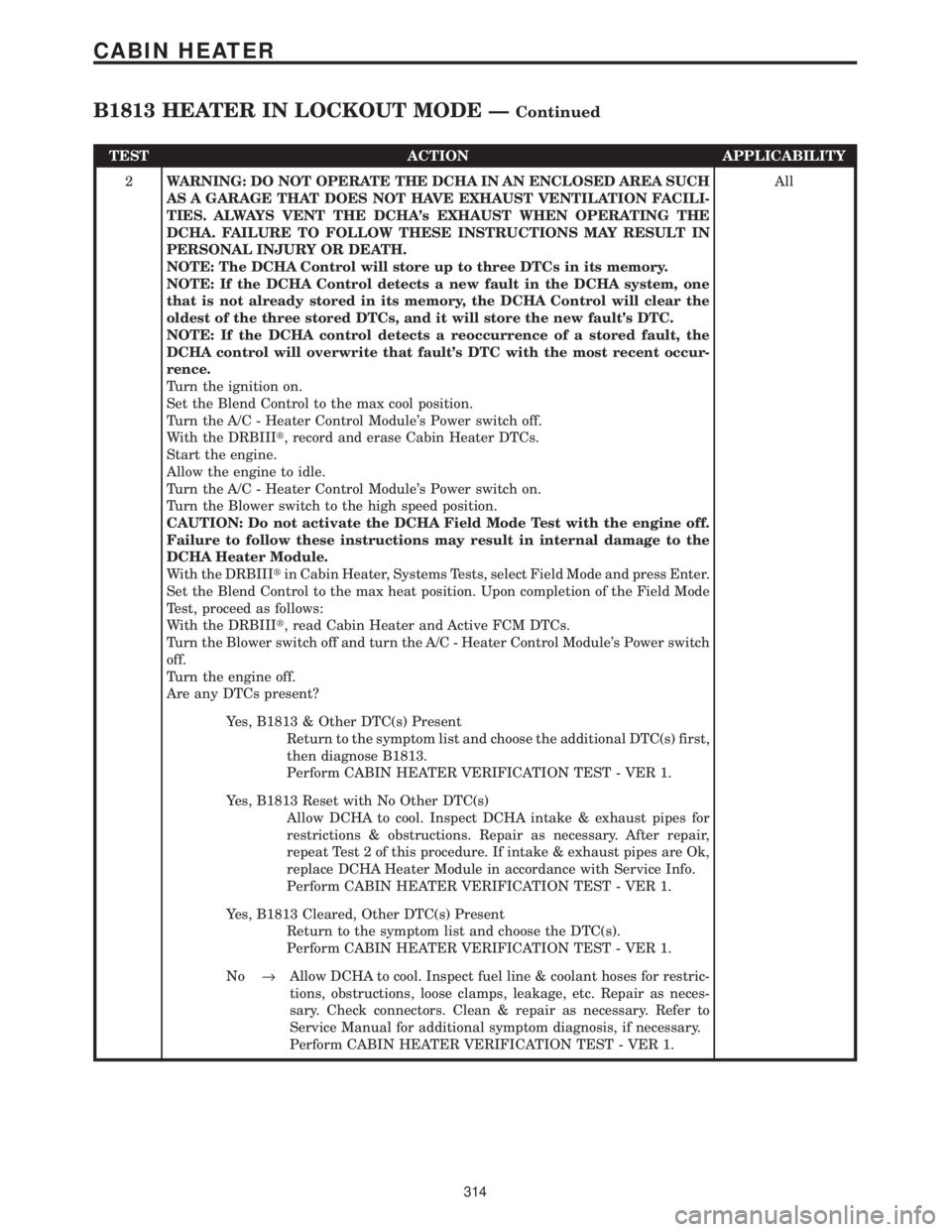
TEST ACTION APPLICABILITY
2WARNING: DO NOT OPERATE THE DCHA IN AN ENCLOSED AREA SUCH
AS A GARAGE THAT DOES NOT HAVE EXHAUST VENTILATION FACILI-
TIES. ALWAYS VENT THE DCHA's EXHAUST WHEN OPERATING THE
DCHA. FAILURE TO FOLLOW THESE INSTRUCTIONS MAY RESULT IN
PERSONAL INJURY OR DEATH.
NOTE: The DCHA Control will store up to three DTCs in its memory.
NOTE: If the DCHA Control detects a new fault in the DCHA system, one
that is not already stored in its memory, the DCHA Control will clear the
oldest of the three stored DTCs, and it will store the new fault's DTC.
NOTE: If the DCHA control detects a reoccurrence of a stored fault, the
DCHA control will overwrite that fault's DTC with the most recent occur-
rence.
Turn the ignition on.
Set the Blend Control to the max cool position.
Turn the A/C - Heater Control Module's Power switch off.
With the DRBIIIt, record and erase Cabin Heater DTCs.
Start the engine.
Allow the engine to idle.
Turn the A/C - Heater Control Module's Power switch on.
Turn the Blower switch to the high speed position.
CAUTION: Do not activate the DCHA Field Mode Test with the engine off.
Failure to follow these instructions may result in internal damage to the
DCHA Heater Module.
With the DRBIIItin Cabin Heater, Systems Tests, select Field Mode and press Enter.
Set the Blend Control to the max heat position. Upon completion of the Field Mode
Test, proceed as follows:
With the DRBIIIt, read Cabin Heater and Active FCM DTCs.
Turn the Blower switch off and turn the A/C - Heater Control Module's Power switch
off.
Turn the engine off.
Are any DTCs present?All
Yes, B1813 & Other DTC(s) Present
Return to the symptom list and choose the additional DTC(s) first,
then diagnose B1813.
Perform CABIN HEATER VERIFICATION TEST - VER 1.
Yes, B1813 Reset with No Other DTC(s)
Allow DCHA to cool. Inspect DCHA intake & exhaust pipes for
restrictions & obstructions. Repair as necessary. After repair,
repeat Test 2 of this procedure. If intake & exhaust pipes are Ok,
replace DCHA Heater Module in accordance with Service Info.
Perform CABIN HEATER VERIFICATION TEST - VER 1.
Yes, B1813 Cleared, Other DTC(s) Present
Return to the symptom list and choose the DTC(s).
Perform CABIN HEATER VERIFICATION TEST - VER 1.
No®Allow DCHA to cool. Inspect fuel line & coolant hoses for restric-
tions, obstructions, loose clamps, leakage, etc. Repair as neces-
sary. Check connectors. Clean & repair as necessary. Refer to
Service Manual for additional symptom diagnosis, if necessary.
Perform CABIN HEATER VERIFICATION TEST - VER 1.
314
CABIN HEATER
B1813 HEATER IN LOCKOUT MODE ÐContinued
Page 348 of 4284
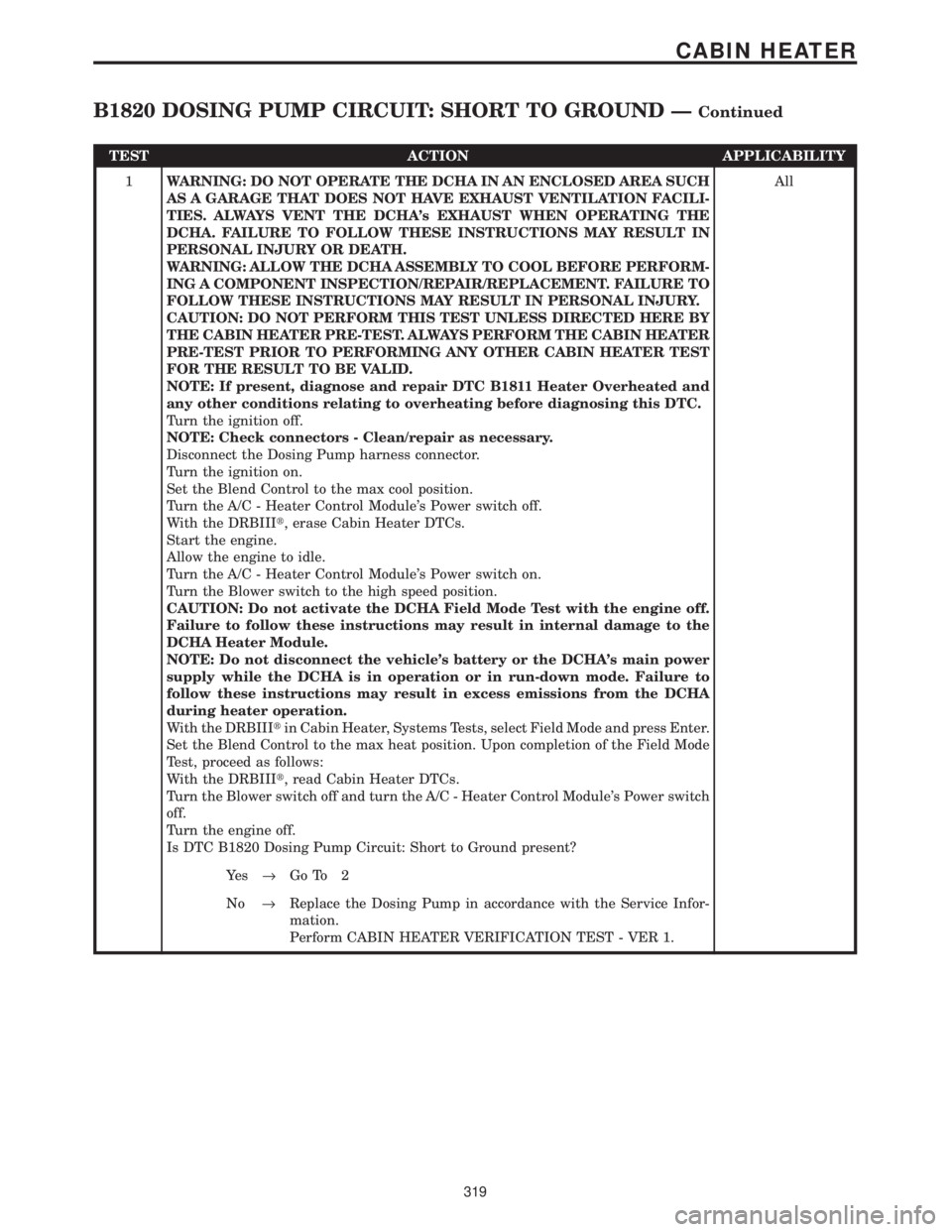
TEST ACTION APPLICABILITY
1WARNING: DO NOT OPERATE THE DCHA IN AN ENCLOSED AREA SUCH
AS A GARAGE THAT DOES NOT HAVE EXHAUST VENTILATION FACILI-
TIES. ALWAYS VENT THE DCHA's EXHAUST WHEN OPERATING THE
DCHA. FAILURE TO FOLLOW THESE INSTRUCTIONS MAY RESULT IN
PERSONAL INJURY OR DEATH.
WARNING: ALLOW THE DCHA ASSEMBLY TO COOL BEFORE PERFORM-
ING A COMPONENT INSPECTION/REPAIR/REPLACEMENT. FAILURE TO
FOLLOW THESE INSTRUCTIONS MAY RESULT IN PERSONAL INJURY.
CAUTION: DO NOT PERFORM THIS TEST UNLESS DIRECTED HERE BY
THE CABIN HEATER PRE-TEST. ALWAYS PERFORM THE CABIN HEATER
PRE-TEST PRIOR TO PERFORMING ANY OTHER CABIN HEATER TEST
FOR THE RESULT TO BE VALID.
NOTE: If present, diagnose and repair DTC B1811 Heater Overheated and
any other conditions relating to overheating before diagnosing this DTC.
Turn the ignition off.
NOTE: Check connectors - Clean/repair as necessary.
Disconnect the Dosing Pump harness connector.
Turn the ignition on.
Set the Blend Control to the max cool position.
Turn the A/C - Heater Control Module's Power switch off.
With the DRBIIIt, erase Cabin Heater DTCs.
Start the engine.
Allow the engine to idle.
Turn the A/C - Heater Control Module's Power switch on.
Turn the Blower switch to the high speed position.
CAUTION: Do not activate the DCHA Field Mode Test with the engine off.
Failure to follow these instructions may result in internal damage to the
DCHA Heater Module.
NOTE: Do not disconnect the vehicle's battery or the DCHA's main power
supply while the DCHA is in operation or in run-down mode. Failure to
follow these instructions may result in excess emissions from the DCHA
during heater operation.
With the DRBIIItin Cabin Heater, Systems Tests, select Field Mode and press Enter.
Set the Blend Control to the max heat position. Upon completion of the Field Mode
Test, proceed as follows:
With the DRBIIIt, read Cabin Heater DTCs.
Turn the Blower switch off and turn the A/C - Heater Control Module's Power switch
off.
Turn the engine off.
Is DTC B1820 Dosing Pump Circuit: Short to Ground present?All
Ye s®Go To 2
No®Replace the Dosing Pump in accordance with the Service Infor-
mation.
Perform CABIN HEATER VERIFICATION TEST - VER 1.
319
CABIN HEATER
B1820 DOSING PUMP CIRCUIT: SHORT TO GROUND ÐContinued
Page 362 of 4284

TEST ACTION APPLICABILITY
3WARNING: DO NOT OPERATE THE DCHA IN AN ENCLOSED AREA SUCH
AS A GARAGE THAT DOES NOT HAVE EXHAUST VENTILATION FACILI-
TIES. ALWAYS VENT THE DCHA's EXHAUST WHEN OPERATING THE
DCHA. FAILURE TO FOLLOW THESE INSTRUCTIONS MAY RESULT IN
PERSONAL INJURY OR DEATH.
Turn the ignition on.
With the DRBIIIt, check for FCM and HVAC DTCs.
Does the DRBIIItdisplay any FCM or HVAC DTCs?All
Ye s®For FCM DTCs, return to the symptom list and choose the
symptom(s). Also, refer to Intelligent Power Module for related
symptom(s). For HVAC DTCs, refer to Heater & A/C for related
symptom(s).
Perform CABIN HEATER VERIFICATION TEST - VER 1.
No®Go To 4
4WARNING: DO NOT OPERATE THE DCHA IN AN ENCLOSED AREA SUCH
AS A GARAGE THAT DOES NOT HAVE EXHAUST VENTILATION FACILI-
TIES. ALWAYS VENT THE DCHA's EXHAUST WHEN OPERATING THE
DCHA. FAILURE TO FOLLOW THESE INSTRUCTIONS MAY RESULT IN
PERSONAL INJURY OR DEATH.
Start the engine.
Allow the engine to idle.
Turn the A/C - Heater Control Module's Power switch on.
Turn the Blower switch to the high speed position.
CAUTION: Do not activate the Diesel Cabin Heater Test with the engine off.
Failure to follow these instructions may result in internal damage to the
DCHA Heater Module.
NOTE: Do not disconnect the vehicle's battery or the DCHA's main power
supply while the DCHA is in operation or in run-down mode. Failure to
follow these instructions may result in excess emissions from the DCHA
during heater operation.
With the DRBIIItin HVAC, Systems Tests, select Diesel Cabin Heater Test and press
#1.
With the DRBIIItin HVAC, Systems Tests, Diesel Cabin Heater Test, read the Cabin
Heater Status.
Does the Status display: On?All
Ye s®Replace the FCM in accordance with the Service Information.
Perform CABIN HEATER VERIFICATION TEST - VER 1.
No®Replace the A/C - Heater Control Module in accordance with the
Service Information.
Perform CABIN HEATER VERIFICATION TEST - VER 1.
333
CABIN HEATER
*CABIN HEATER INOPERABLE FROM A/C - HEATER MODULE Ð
Continued
Page 431 of 4284

Symptom:
*NO RESPONSE FROM ECM (SCI ONLY) - DIESEL ONLY
POSSIBLE CAUSES
CHECK ECM POWERS AND GROUNDS
CABIN HEATER ASSIST
SCI TRANSMIT CIRCUIT SHORTED TO VOLTAGE
SCI TRANSMIT CIRCUIT SHORTED TO GROUND
SCI TRANSMIT CIRCUIT OPEN
ENGINE CONTROL MODULE
TEST ACTION APPLICABILITY
1 Perform the symptom Checking ECM Power and Ground Circuits in the Driveability
category.
Did the vehicle pass this test?All
Ye s®Go To 2
No®Repair as necessary.
Perform ROAD TEST VERIFICATION - VER-2.
2 Turn the ignition off.
Disconnect the ECM harness connectors.
Disconnect the DRB from the DLC.
Measure the resistance between ground and the SCI Transmit circuit.
Is the resistance below 5.0 ohms?All
Ye s®Go To 3
No®Go To 4
3 Turn the ignition off.
Disconnect the Cabin Heater Assist C1 harness connector.
Measure the resistance between ground and the SCI Transmit circuit.
Is the resistance below 5.0 ohms?All
Ye s®Repair the SCI Transmit circuit for a short to ground.
Perform ROAD TEST VERIFICATION - VER-2.
No®Replace the Cabin Heater Assist in accordance with the service
information.
Perform ROAD TEST VERIFICATION - VER-2.
4 Turn the ignition off.
Disconnect the DRB from the DLC.
Disconnect the ECM harness connectors.
Disconnect the Cabin Heater Assist C1 harness connector.
Turn the ignition on.
Measure the voltage of the SCI Transmit circuit at the DLC connector (cav 7).
Is the voltage above 1.0 volt?All
Ye s®Repair the SCI Transmit circuit for a short to voltage.
Perform ROAD TEST VERIFICATION - VER-2.
No®Go To 5
402
COMMUNICATION
Page 450 of 4284

TEST ACTION APPLICABILITY
3 Turn the ignition off.
Disconnect the TCM harness connector.
Remove the starter relay from the IPM.
Using a 12-volt test light connected to ground, probe the Ignition Switch Output
(Start) circuit.
Note: The light must illuminate brightly, if it does not light, or lights dimly,
the circuit must be repaired. If there is any doubt, compare the brightness
when testing the circuit, to the brightness when connected directly to the
battery positive post.
Observe the test light while momentarily turning the ignition switch to the Start
position.
Is the test light illuminated?All
Ye s®Go To 4
No®Repair the Ignition Switch Output (Start) circuit for an open.
Refer to the wiring diagrams located in the Service Information.
Perform 41TE TRANSMISSION VERIFICATION TEST - VER 1.
Note: Reinstall the original Starter Relay.
4 Turn the ignition off.
Disconnect the TCM harness connector.
Using a 12-volt test light connected to ground, probe the Fused B(+) circuit.
Note: The light must illuminate brightly, if it does not light, or lights dimly,
the circuit must be repaired. If there is any doubt, compare the brightness
when testing the circuit, to the brightness when connected directly to the
battery positive post.
Is the test light illuminated?All
Ye s®Go To 5
No®Check IPM fuse #15 for an open. If OK, repair the Fused B(+)
circuit for an open. Refer to the wiring diagrams located in the
Service Information.
Perform 41TE TRANSMISSION VERIFICATION TEST - VER 1.
5 Turn the ignition off.
Disconnect the TCM harness connector.
Using a 12-volt test light connected to 12-volts, probe each ground circuit in the TCM
connector.
NOTE: The light must illuminate brightly, if it does not light, or lights dimly,
the circuit must be repaired. If there is any doubt, compare the brightness
when testing the circuit, to the brightness when connected directly to the
battery negative post.
Is the light illuminated at all ground circuits?All
Ye s®Go To 6
No®Repair the Ground circuit(s) for an open. Check the main ground
connection to engine block and/or chassis. Refer to the wiring
diagrams located in the Service Information.
Perform 41TE TRANSMISSION VERIFICATION TEST - VER 1.
421
COMMUNICATION
*NO RESPONSE FROM TRANSMISSION CONTROL MODULE ÐContinued