CHRYSLER VOYAGER 2001 Service Manual
Manufacturer: CHRYSLER, Model Year: 2001, Model line: VOYAGER, Model: CHRYSLER VOYAGER 2001Pages: 4284, PDF Size: 83.53 MB
Page 2861 of 4284

FRAMES & BUMPERS
TABLE OF CONTENTS
page page
BUMPERS
DESCRIPTION............................1
SPECIFICATIONS.........................1
FRONT FASCIA
REMOVAL...............................2
INSTALLATION............................2
FRONT BUMPER REINFORCEMENT
REMOVAL...............................2
INSTALLATION............................3
REAR FASCIA
REMOVAL...............................3
INSTALLATION............................3
REAR BUMPER REINFORCEMENT
REMOVAL...............................3INSTALLATION............................4
REAR FASCIA - SCUFF PAD
REMOVAL...............................4
INSTALLATION............................4
FRAME
DESCRIPTION............................4
SPECIFICATIONS.........................4
FRONT CRADLE CROSSMEMBER
DESCRIPTION............................9
REMOVAL..............................10
INSTALLATION...........................11
FRONT CROSSMEMBER MOUNT BUSHINGS
REMOVAL..............................11
INSTALLATION...........................11
BUMPERS
DESCRIPTION
BUMPERS
The bumpers are made up of bumper reinforce-
ment and fascia with air deflector (front bumper) and
mounting brackets.The bumper reinforcement is fastened to the unit-
ized body frame rails on the front and to the rail
extensions on the rear. The bumper fascia is fastened
to the body side sheet metal.
SPECIFICATIONS
TORQUE SPECIFICATIONS
DESCRIPTION N´m Ft. Lbs. In. Lbs.
Front bumper reinforcement attaching nut 54 40 Ð
Rear bumper reinforcement attaching nut 27 20 Ð
RSFRAMES & BUMPERS13-1
Page 2862 of 4284

FRONT FASCIA
REMOVAL
(1) Release hood latch and open hood.
(2) Remove the headlamp assemblies. Refer to
group 8 exterior lighting.
(3) Remove two bolts attaching the upper grill sup-
port to the headlamp mounting panel at each side of
the grille.
(4) Hoist vehicle and support with safety stands.
(5)
Remove front wheels. Refer to Group 22, Wheels
and Tires, for proper procedures and sequence.
(6) Remove front wheelhouse splash shields fasten-
ers as necessary to gain access to bolts holding front
fascia to fender. Refer to Group 23, Body, for proper
procedures.
(7) Remove the two bolts and two nuts holding fas-
cia to the front fenders (Fig. 1).
(8) Remove the five bolts holding bottom of fascia/
air dam to radiator closure panel.
(9) Disconnect fog lamp/parking and turn signal
lamp wire connector, as necessary.
(10) Remove bumper fascia from vehicle.
INSTALLATION
(1) Position front bumper fascia on vehicle.
(2) Lower vehicle.
(3) Install the two bolts to hold fascia to headlamp
mounting panel at each side of grille.(4) Raise vehicle.
(5) Install the two bolts and two nuts to hold fas-
cia to the front fenders (Fig. 1). The fascia should be
flush to fender.
(6) Install front wheelhouse splash shields fasten-
ers. Refer to Group 23, Body, for proper procedures.
(7) Install front wheels. Refer to Group 22, Wheels
and Tires, for proper procedures and tightening
sequence.
(8) Install the five bolts to hold bottom of fascia to
radiator closure panel.
(9) Lower the vehicle.
(10) Install the headlamp assemblies. Refer to sec-
tion 8 for installation.
FRONT BUMPER
REINFORCEMENT
REMOVAL
(1) Remove front bumper fascia. (Refer to 13 -
FRAMES & BUMPERS/BUMPERS/FRONT FASCIA
- REMOVAL)
(2) Support front bumper reinforcement on a suit-
able lifting device.
(3) Remove the four nuts holding front bumper
reinforcement to frame rail (Fig. 2).
(4) Remove front bumper reinforcement from vehicle.
Fig. 1 FRONT BUMPER FASCIA
1 - FRONT BUMPER FASCIA
2 - FRONT BUMPER REINFORCEMENT
3 - RADIATOR ENCLOSURE
Fig. 2 FRT BUMPER REINFORCEMENT
1 - FRONT BUMPER REINFORCEMENT
2 - FRAME RAILS
13 - 2 FRAMES & BUMPERSRS
Page 2863 of 4284

INSTALLATION
NOTE: Check position of the arrows molded into
the foam for correct orientation.
(1) Position front bumper reinforcement on vehicle.
(2) Install the four nuts to hold reinforcement to
frame rails. Tighten nuts to 54 N´m (40 ft. lbs.)
torque.
(3) Install front fascia. (Refer to 13 - FRAMES &
BUMPERS/BUMPERS/FRONT FASCIA - INSTAL-
LATION)
REAR FASCIA
REMOVAL
(1) Open liftgate.
(2) Remove the two screws attaching the upper
fascia to the body.
(3) Hoist and support vehicle on safety stands.
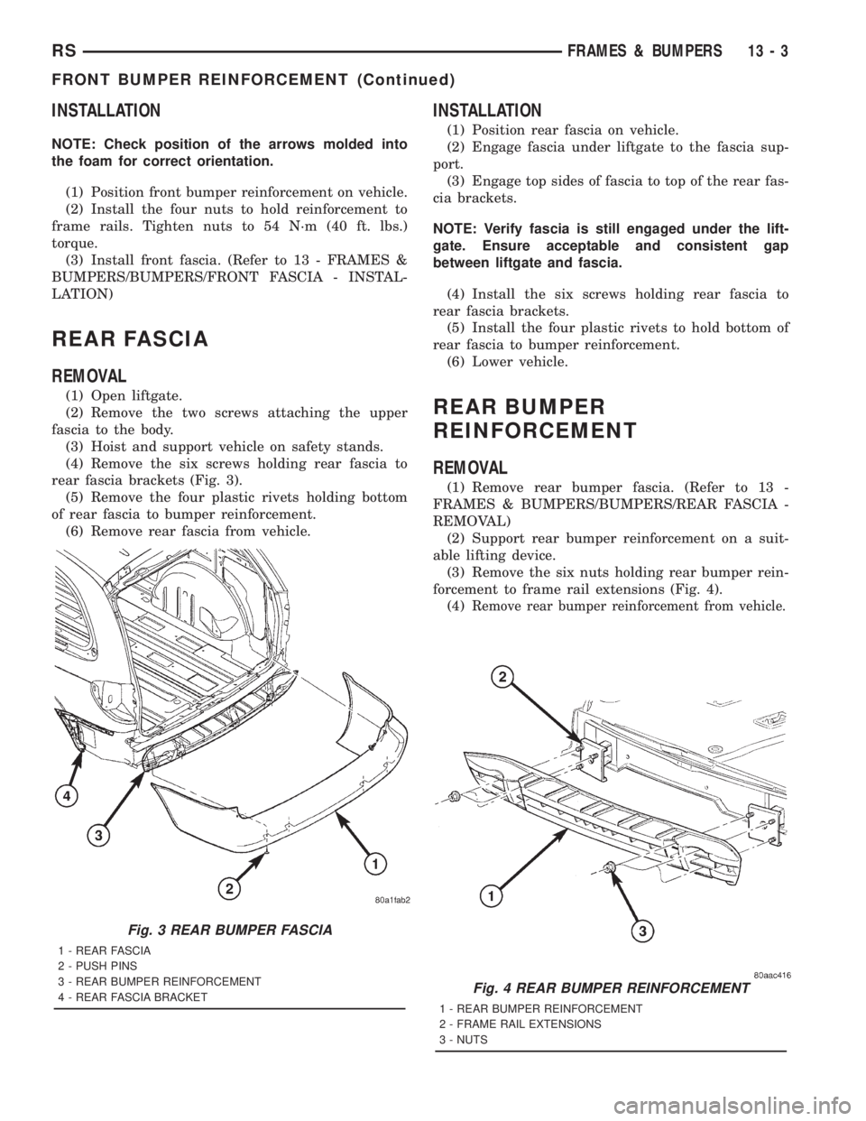
(4) Remove the six screws holding rear fascia to
rear fascia brackets (Fig. 3).
(5) Remove the four plastic rivets holding bottom
of rear fascia to bumper reinforcement.
(6) Remove rear fascia from vehicle.
INSTALLATION
(1) Position rear fascia on vehicle.
(2) Engage fascia under liftgate to the fascia sup-
port.
(3) Engage top sides of fascia to top of the rear fas-
cia brackets.
NOTE: Verify fascia is still engaged under the lift-
gate. Ensure acceptable and consistent gap
between liftgate and fascia.
(4) Install the six screws holding rear fascia to
rear fascia brackets.
(5) Install the four plastic rivets to hold bottom of
rear fascia to bumper reinforcement.
(6) Lower vehicle.
REAR BUMPER
REINFORCEMENT
REMOVAL
(1) Remove rear bumper fascia. (Refer to 13 -
FRAMES & BUMPERS/BUMPERS/REAR FASCIA -
REMOVAL)
(2) Support rear bumper reinforcement on a suit-
able lifting device.
(3) Remove the six nuts holding rear bumper rein-
forcement to frame rail extensions (Fig. 4).
(4)
Remove rear bumper reinforcement from vehicle.
Fig. 3 REAR BUMPER FASCIA
1 - REAR FASCIA
2 - PUSH PINS
3 - REAR BUMPER REINFORCEMENT
4 - REAR FASCIA BRACKET
Fig. 4 REAR BUMPER REINFORCEMENT
1 - REAR BUMPER REINFORCEMENT
2 - FRAME RAIL EXTENSIONS
3 - NUTS
RSFRAMES & BUMPERS13-3
FRONT BUMPER REINFORCEMENT (Continued)
Page 2864 of 4284

INSTALLATION
(1) Position rear bumper reinforcement on vehicle.
(2) Install the six nuts to hold rear bumper rein-
forcement to frame rail extensions and tighten to 27
N´m (20 ft. lbs.) (Fig. 4).
(3) Install rear bumper fascia. (Refer to 13 -
FRAMES & BUMPERS/BUMPERS/REAR FASCIA -
INSTALLATION)
REAR FASCIA - SCUFF PAD
REMOVAL
The scuff pad may not be salvageable during the
removal process. The scuff pad should be replaced if
damaged or broken. Check availability before servic-
ing.
(1) Remove rear bumper fascia.(Refer to 13 -
FRAMES & BUMPERS/BUMPERS/REAR FASCIA -
REMOVAL)
(2) Using a trim stick, pry up the rear edge of the
scuff pad to release tabs from the rear bumper fascia
and pull scuff pad up to release the forward tabs
(Fig. 5).
INSTALLATION
(1) Verify that there are fifteen slots in the fascia.
(2) Place scuff pad in position.
(3) Align and insert the center forward tab.
(4) Align the remaining tabs and press into the
slots, starting in the center and working outboard.
(5) Assure all tabs are fully engaged into the fas-
cia.
FRAME
DESCRIPTION
The vehicle does not have a conventional frame. It
is constructed as a unitized body and frame. The uni-
body is constructed from special high strength steel
and coated metals. This process reduces weight and
provides strength to withstand the forces applied
against structural members. The structural members
provide a unibody that has great structural strength.
SPECIFICATIONS
FRAME DIMENSIONS
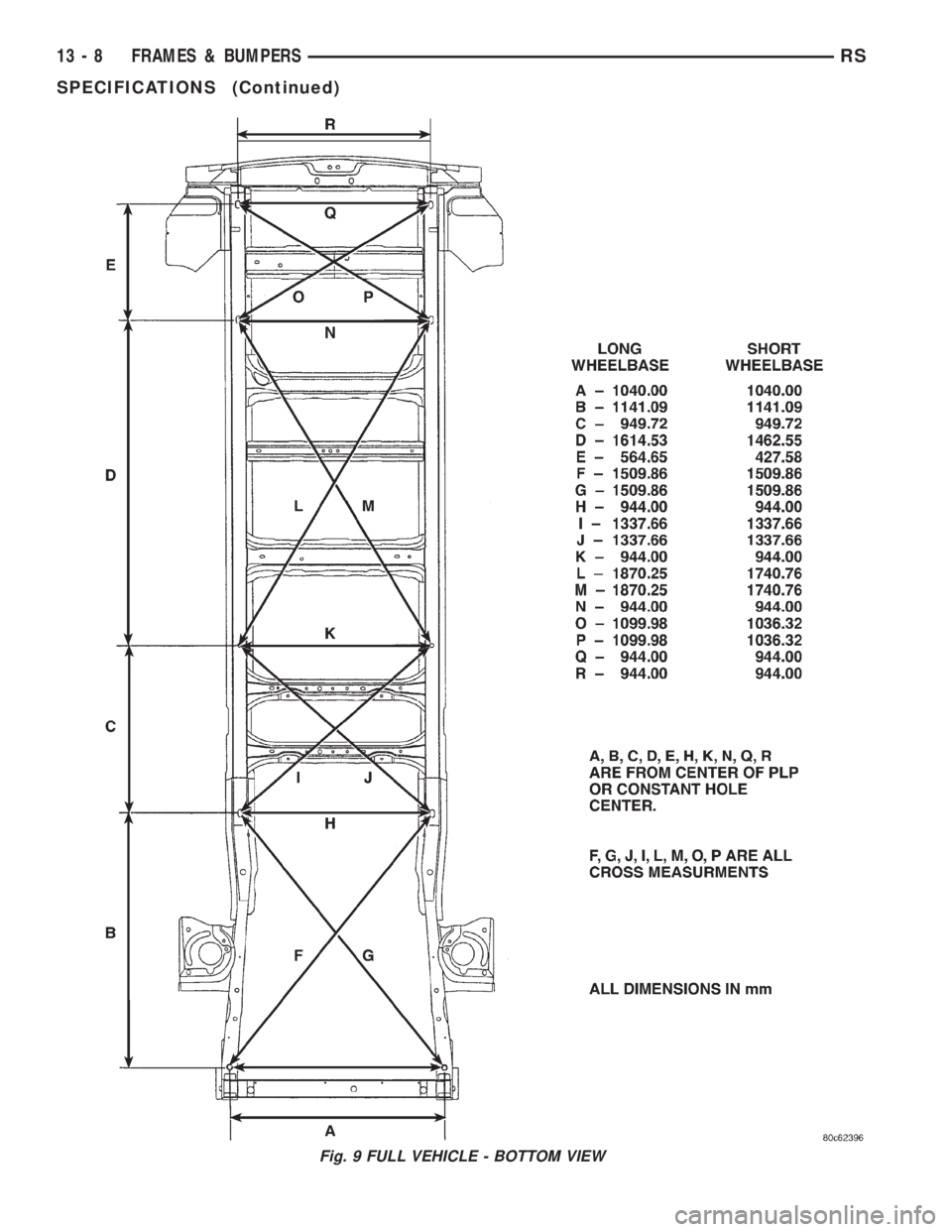
Frame dimensions are listed in metric scale. All
dimensions are from center to center of Principal
Locating Point (PLP), or from center to center of PLP
and fastener location.
VEHICLE PREPARATION
Position the vehicle on a frame alignment rack,
refer to instructions provided with equipment being
used. Adjust the vehicle PLP heights to the specified
dimension above the work surface (datum line). Ver-
tical dimensions can be taken from the datum line to
the locations indicated were applicable. Refer to (Fig.
6), (Fig. 7), (Fig. 8), and (Fig. 9) for proper dimen-
sions.
Fig. 5 Scuff Pad
1 - SCUFF PAD
2 - TABS
13 - 4 FRAMES & BUMPERSRS
REAR BUMPER REINFORCEMENT (Continued)
Page 2865 of 4284

Fig. 6 CROSSMEMBER DIMENSIONS
RSFRAMES & BUMPERS13-5
SPECIFICATIONS (Continued)
Page 2866 of 4284

Fig. 7 ENGINE BOX - TOP VIEW
13 - 6 FRAMES & BUMPERSRS
SPECIFICATIONS (Continued)
Page 2867 of 4284

Fig. 8 ENGINE COMPARTMENT AND FRAME RAIL - SIDE VIEW
RSFRAMES & BUMPERS13-7
SPECIFICATIONS (Continued)
Page 2868 of 4284

Fig. 9 FULL VEHICLE - BOTTOM VIEW
13 - 8 FRAMES & BUMPERSRS
SPECIFICATIONS (Continued)
Page 2869 of 4284

SPECIFICATIONS - TORQUE
DESCRIPTION N´m Ft. Lbs. In. Lbs.
Front Cradle Crossmember to Fram Rail Attaching Bolts (4) 163 120 Ð
Reinforcement Plate to Crossmember Attaching Bolt Size M14 (9) 167 123 Ð
Reinforcement Plate to Crossmember Attaching Bolt Size M12 (1) 108 80 Ð
Reinforcement Plate to Crossmember Attaching Bolt Size M10 (4) 68 50 Ð
Rear Engine Mount to Crossmember Attaching Through Bolt 68 50 Ð
Radiator Support Crossmember Attaching Bolts 51 38 Ð
FRONT CRADLE
CROSSMEMBER
DESCRIPTION - FRONT CRADLE
CROSSMEMBER
This vehicle uses a one piece cast aluminum cradle
for the front cradle crossmember. The cradle cross-
member is used as the attaching points for the lower
control arms, stabilizer bar and steering gear. The
cradle also has the power steering hoses and the
chassis brake tubes attached to it.
WARNING: If a threaded hole in the suspension cra-
dle needs to be repaired, only use the type of
thread insert and installation procedure specified
for this application.
The threaded holes in the front cradle crossmem-
ber that are used for attachment of the lower control
arm rear bushing retainer, power steering hose and
chassis brake tubes can be repaired. The repair is
done by the installation of a Heli-Coiltthread insert
which has been specifically developed for this appli-
cation. Refer to the Mopar Parts Catalog for the spec-
ified Heli-Coiltthread insert to be used for this
application. The procedure for installing the Heli-
Coiltthread insert is detailed in the Service Proce-
dures section in this group of the service manual.
DESCRIPTION - FRONT CRADLE
CROSSMEMBER THREAD REPAIR
WARNING: When performing this procedure use
only the thread inserts which are specified in the
Mopar Parts Catalog for this repair procedure.
These thread inserts have been specifically devel-
oped for this application and use of other types of
thread inserts can result in an inferior long term
repair.
The threaded holes in the front cradle crossmem-
ber, if damaged, can repaired by installing a Heli-
Coiltthread insert.The threaded holes that are repairable using the
thread insert, are the lower control arm rear bushing
retainer mounting bolt holes, routing bracket attach-
ing locations for the power steering hoses, and brake
hose attachment holes.
This repair procedure now allows the threaded
holes in the cradle crossmember to be repaired, elim-
inating the need to replace the cradle crossmember if
damage occurs to one of the threaded holes.
The thread inserts for this application are specified
by part number in the Mopar Parts Catalog.Do not
use a substitute thread insert.
The specific tools and equipment required to install
the thread insert are listed below. Refer to the
instructions included with the thread insert for the
detailed procedure used for the installation of the
thread insert.
NOTE: The thread inserts for this application are for
the repair of M8x1.25 and M10x1.5 threads. Be sure
the correct tools are used for the required thread
insert size.
TOOL REQUIREMENT FOR M8x1.25 Thread
²8.3mm (5/16 in.) Drill Bit
²120É Countersink
²Heli-CoiltTap #4863-8
²Heli-CoiltGage #4624-8
²Heli-CoiltHand Inserting Tool 7751-8
²Needle Nose Pliers ± For Removal Of Thread
Insert Driving Tang
TOOL REQUIREMENT FOR M10x1.5 Thread
²10.5mm (25/64 in.) Drill Bit
²120É Countersink
²Heli-CoiltTap #4863-10
²Heli-CoiltGage #4624-10
²Heli-CoiltHand Inserting Tool 7751-10
RSFRAMES & BUMPERS13-9
SPECIFICATIONS (Continued)
Page 2870 of 4284

²Needle Nose Pliers ± For Removal Of Thread
Insert Driving Tang
REMOVAL
The front cradle crossmember must be installed in
the design location to achieve proper front end sus-
pension alignment. If the cradle crossmember is
removed without applying reference marks on the
frame rails, align the cradle crossmember according
to the dimensions provided in this group.
NOTE: If the caged nuts in the frame rails become
damaged and cannot be reused, a replacement nut
can be obtained through MoparT.
REMOVAL
(1) Disconnect battery negative cable.
(2) Remove steering column lower cover from
instrument panel. Refer to Group 8E, Instrument
Panel and Systems.
(3) Remove knee blocker reinforcement. Refer to
Group 8E, Instrument Panel and Systems.
(4) Position steering so front wheels are straight
ahead.
CAUTION: Do not rotate steering wheel after disen-
gaging lower coupling from steering gear, damage
to air bag clock spring can result.
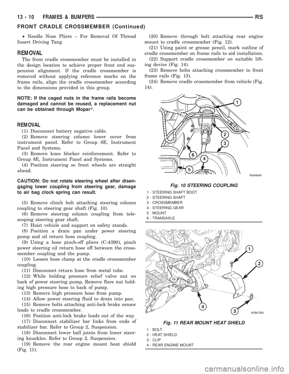
(5) Remove clinch bolt attaching steering column
coupling to steering gear shaft (Fig. 10).
(6) Remove steering column coupling from tele-
scoping steering gear shaft.
(7) Hoist vehicle and support on safety stands.
(8) Position a drain pan under power steering
pump and oil return hose coupling.
(9) Using a hose pinch-off pliers (C-4390), pinch
power steering oil return hose off between the cross-
member coupling and the pump.
(10) Loosen hose clamp at the cradle crossmember
coupling.
(11) Disconnect return hose from metal tube.
(12) While holding pressure relief valve nut on
back of power steering pump, Remove flare nut hold-
ing high pressure hose to back of pump.
(13) Remove high pressure hose from pump.
(14) Allow power steering fluid to drain into pan.
(15) Remove bolts attaching anti-lock brake sensor
leads to cradle crossmember.
(16) Position anti-lock brake leads out of the way.
(17) Disconnect stabilizer bar links from ends of
stabilizer bar. Refer to Group 2, Suspension.
(18) Disconnect lower ball joints from lower steer-
ing knuckles. Refer to Group 2, Suspension.
(19) Remove the rear engine mount heat shield
(Fig. 11).(20) Remove through bolt attaching rear engine
mount to cradle crossmember (Fig. 12).
(21) Using paint or grease pencil, mark outline of
cradle crossmember on frame rails to aid installation.
(22) Support cradle crossmember on suitable lift-
ing device (Fig. 14).
(23) Remove bolts attaching crossmember to front
frame rails (Fig. 13).
(24) Remove cradle crossmember from vehicle (Fig.
14).
Fig. 10 STEERING COUPLING
1 - STEERING SHAFT BOOT
2 - STEERING SHAFT
3 - CROSSMEMBER
4 - STEERING GEAR
5 - MOUNT
6 - TRANSAXLE
Fig. 11 REAR MOUNT HEAT SHIELD
1 - BOLT
2 - HEAT SHIELD
3 - CLIP
4 - REAR ENGINE MOUNT
13 - 10 FRAMES & BUMPERSRS
FRONT CRADLE CROSSMEMBER (Continued)