CHRYSLER VOYAGER 2001 Service Manual
Manufacturer: CHRYSLER, Model Year: 2001, Model line: VOYAGER, Model: CHRYSLER VOYAGER 2001Pages: 4284, PDF Size: 83.53 MB
Page 3011 of 4284
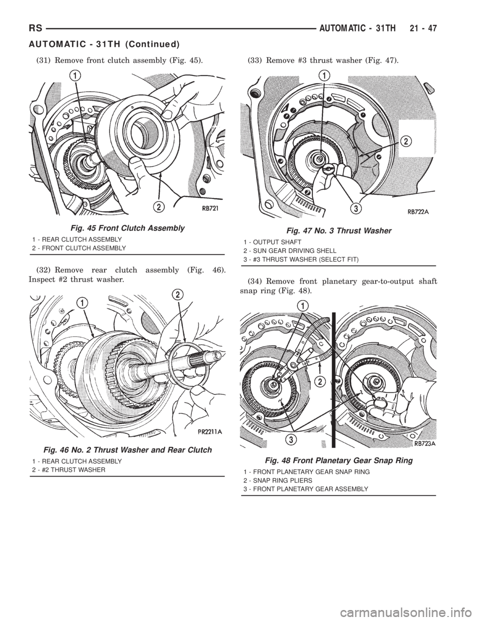
(31) Remove front clutch assembly (Fig. 45).
(32) Remove rear clutch assembly (Fig. 46).
Inspect #2 thrust washer.(33) Remove #3 thrust washer (Fig. 47).
(34) Remove front planetary gear-to-output shaft
snap ring (Fig. 48).
Fig. 45 Front Clutch Assembly
1 - REAR CLUTCH ASSEMBLY
2 - FRONT CLUTCH ASSEMBLY
Fig. 46 No. 2 Thrust Washer and Rear Clutch
1 - REAR CLUTCH ASSEMBLY
2 - #2 THRUST WASHER
Fig. 47 No. 3 Thrust Washer
1 - OUTPUT SHAFT
2 - SUN GEAR DRIVING SHELL
3 - #3 THRUST WASHER (SELECT FIT)
Fig. 48 Front Planetary Gear Snap Ring
1 - FRONT PLANETARY GEAR SNAP RING
2 - SNAP RING PLIERS
3 - FRONT PLANETARY GEAR ASSEMBLY
RSAUTOMATIC - 31TH21-47
AUTOMATIC - 31TH (Continued)
Page 3012 of 4284
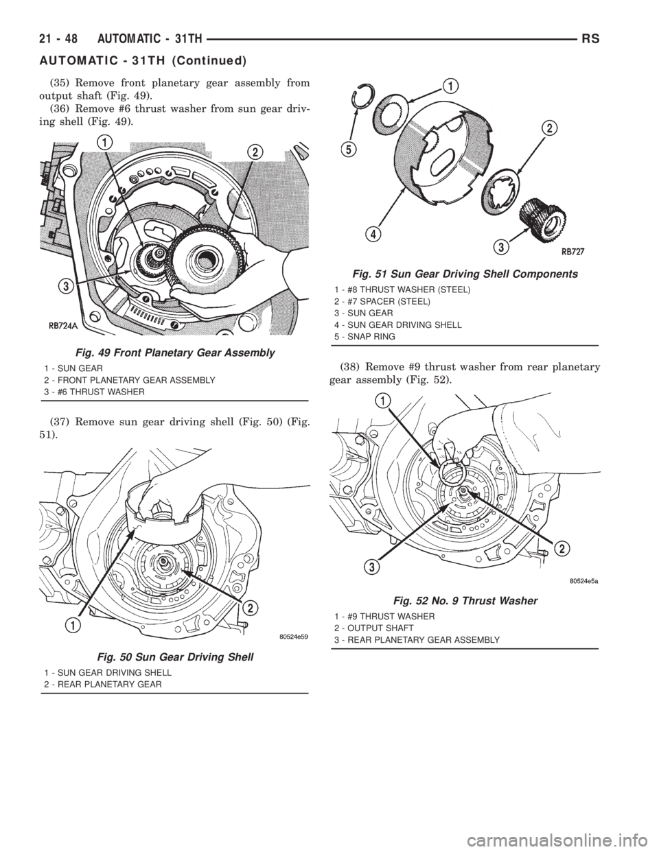
(35) Remove front planetary gear assembly from
output shaft (Fig. 49).
(36) Remove #6 thrust washer from sun gear driv-
ing shell (Fig. 49).
(37) Remove sun gear driving shell (Fig. 50) (Fig.
51).(38) Remove #9 thrust washer from rear planetary
gear assembly (Fig. 52).
Fig. 49 Front Planetary Gear Assembly
1 - SUN GEAR
2 - FRONT PLANETARY GEAR ASSEMBLY
3 - #6 THRUST WASHER
Fig. 50 Sun Gear Driving Shell
1 - SUN GEAR DRIVING SHELL
2 - REAR PLANETARY GEAR
Fig. 51 Sun Gear Driving Shell Components
1 - #8 THRUST WASHER (STEEL)
2 - #7 SPACER (STEEL)
3 - SUN GEAR
4 - SUN GEAR DRIVING SHELL
5 - SNAP RING
Fig. 52 No. 9 Thrust Washer
1 - #9 THRUST WASHER
2 - OUTPUT SHAFT
3 - REAR PLANETARY GEAR ASSEMBLY
21 - 48 AUTOMATIC - 31THRS
AUTOMATIC - 31TH (Continued)
Page 3013 of 4284
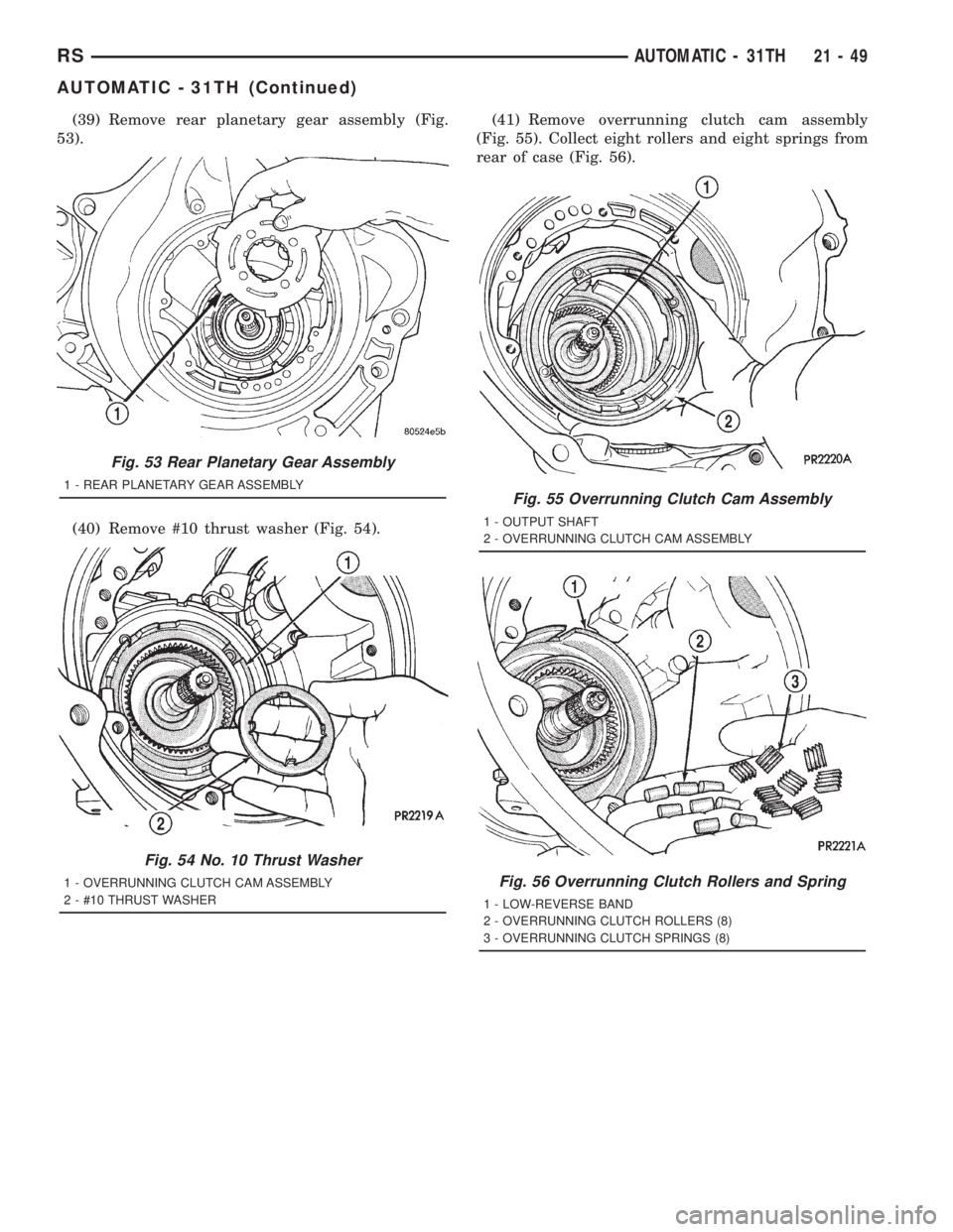
(39) Remove rear planetary gear assembly (Fig.
53).
(40) Remove #10 thrust washer (Fig. 54).(41) Remove overrunning clutch cam assembly
(Fig. 55). Collect eight rollers and eight springs from
rear of case (Fig. 56).
Fig. 53 Rear Planetary Gear Assembly
1 - REAR PLANETARY GEAR ASSEMBLY
Fig. 54 No. 10 Thrust Washer
1 - OVERRUNNING CLUTCH CAM ASSEMBLY
2 - #10 THRUST WASHER
Fig. 55 Overrunning Clutch Cam Assembly
1 - OUTPUT SHAFT
2 - OVERRUNNING CLUTCH CAM ASSEMBLY
Fig. 56 Overrunning Clutch Rollers and Spring
1 - LOW-REVERSE BAND
2 - OVERRUNNING CLUTCH ROLLERS (8)
3 - OVERRUNNING CLUTCH SPRINGS (8)
RSAUTOMATIC - 31TH21-49
AUTOMATIC - 31TH (Continued)
Page 3014 of 4284
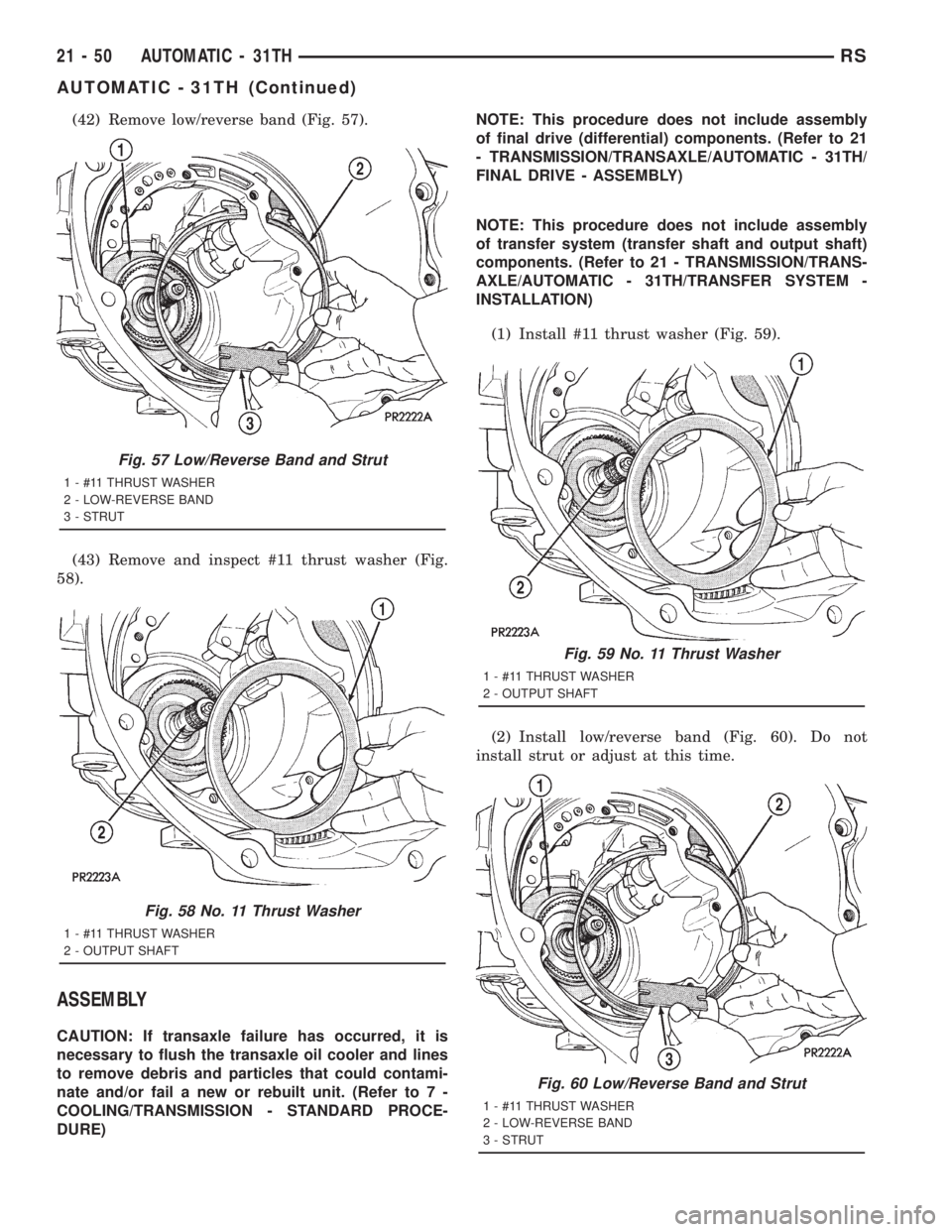
(42) Remove low/reverse band (Fig. 57).
(43) Remove and inspect #11 thrust washer (Fig.
58).
ASSEMBLY
CAUTION: If transaxle failure has occurred, it is
necessary to flush the transaxle oil cooler and lines
to remove debris and particles that could contami-
nate and/or fail a new or rebuilt unit. (Refer to 7 -
COOLING/TRANSMISSION - STANDARD PROCE-
DURE)NOTE: This procedure does not include assembly
of final drive (differential) components. (Refer to 21
- TRANSMISSION/TRANSAXLE/AUTOMATIC - 31TH/
FINAL DRIVE - ASSEMBLY)
NOTE: This procedure does not include assembly
of transfer system (transfer shaft and output shaft)
components. (Refer to 21 - TRANSMISSION/TRANS-
AXLE/AUTOMATIC - 31TH/TRANSFER SYSTEM -
INSTALLATION)
(1) Install #11 thrust washer (Fig. 59).
(2) Install low/reverse band (Fig. 60). Do not
install strut or adjust at this time.
Fig. 57 Low/Reverse Band and Strut
1 - #11 THRUST WASHER
2 - LOW-REVERSE BAND
3 - STRUT
Fig. 58 No. 11 Thrust Washer
1 - #11 THRUST WASHER
2 - OUTPUT SHAFT
Fig. 59 No. 11 Thrust Washer
1 - #11 THRUST WASHER
2 - OUTPUT SHAFT
Fig. 60 Low/Reverse Band and Strut
1 - #11 THRUST WASHER
2 - LOW-REVERSE BAND
3 - STRUT
21 - 50 AUTOMATIC - 31THRS
AUTOMATIC - 31TH (Continued)
Page 3015 of 4284
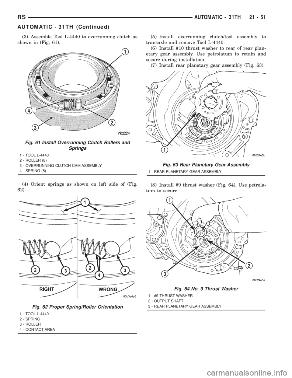
(3) Assemble Tool L-4440 to overrunning clutch as
shown in (Fig. 61).
(4) Orient springs as shown on left side of (Fig.
62).(5) Install overrunning clutch/tool assembly to
transaxle and remove Tool L-4440.
(6) Install #10 thrust washer to rear of rear plan-
etary gear assembly. Use petrolatum to retain and
secure during installation.
(7) Install rear planetary gear assembly (Fig. 63).
(8) Install #9 thrust washer (Fig. 64). Use petrola-
tum to secure.
Fig. 61 Install Overrunning Clutch Rollers and
Springs
1 - TOOL L-4440
2 - ROLLER (8)
3 - OVERRUNNING CLUTCH CAM ASSEMBLY
4 - SPRING (8)
Fig. 62 Proper Spring/Roller Orientation
1 - TOOL L-4440
2 - SPRING
3 - ROLLER
4 - CONTACT AREA
Fig. 63 Rear Planetary Gear Assembly
1 - REAR PLANETARY GEAR ASSEMBLY
Fig. 64 No. 9 Thrust Washer
1 - #9 THRUST WASHER
2 - OUTPUT SHAFT
3 - REAR PLANETARY GEAR ASSEMBLY
RSAUTOMATIC - 31TH21-51
AUTOMATIC - 31TH (Continued)
Page 3016 of 4284
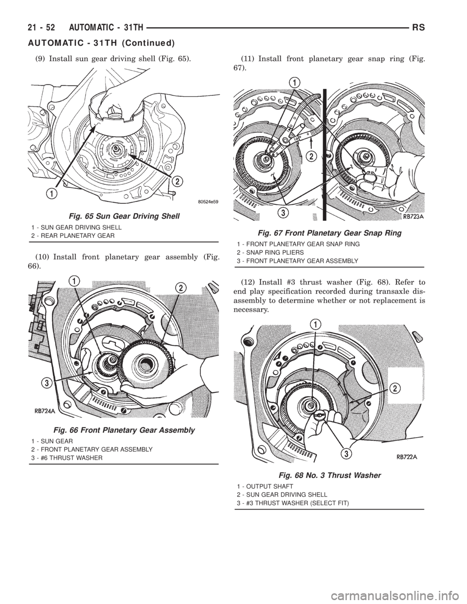
(9) Install sun gear driving shell (Fig. 65).
(10) Install front planetary gear assembly (Fig.
66).(11) Install front planetary gear snap ring (Fig.
67).
(12) Install #3 thrust washer (Fig. 68). Refer to
end play specification recorded during transaxle dis-
assembly to determine whether or not replacement is
necessary.
Fig. 65 Sun Gear Driving Shell
1 - SUN GEAR DRIVING SHELL
2 - REAR PLANETARY GEAR
Fig. 66 Front Planetary Gear Assembly
1 - SUN GEAR
2 - FRONT PLANETARY GEAR ASSEMBLY
3 - #6 THRUST WASHER
Fig. 67 Front Planetary Gear Snap Ring
1 - FRONT PLANETARY GEAR SNAP RING
2 - SNAP RING PLIERS
3 - FRONT PLANETARY GEAR ASSEMBLY
Fig. 68 No. 3 Thrust Washer
1 - OUTPUT SHAFT
2 - SUN GEAR DRIVING SHELL
3 - #3 THRUST WASHER (SELECT FIT)
21 - 52 AUTOMATIC - 31THRS
AUTOMATIC - 31TH (Continued)
Page 3017 of 4284
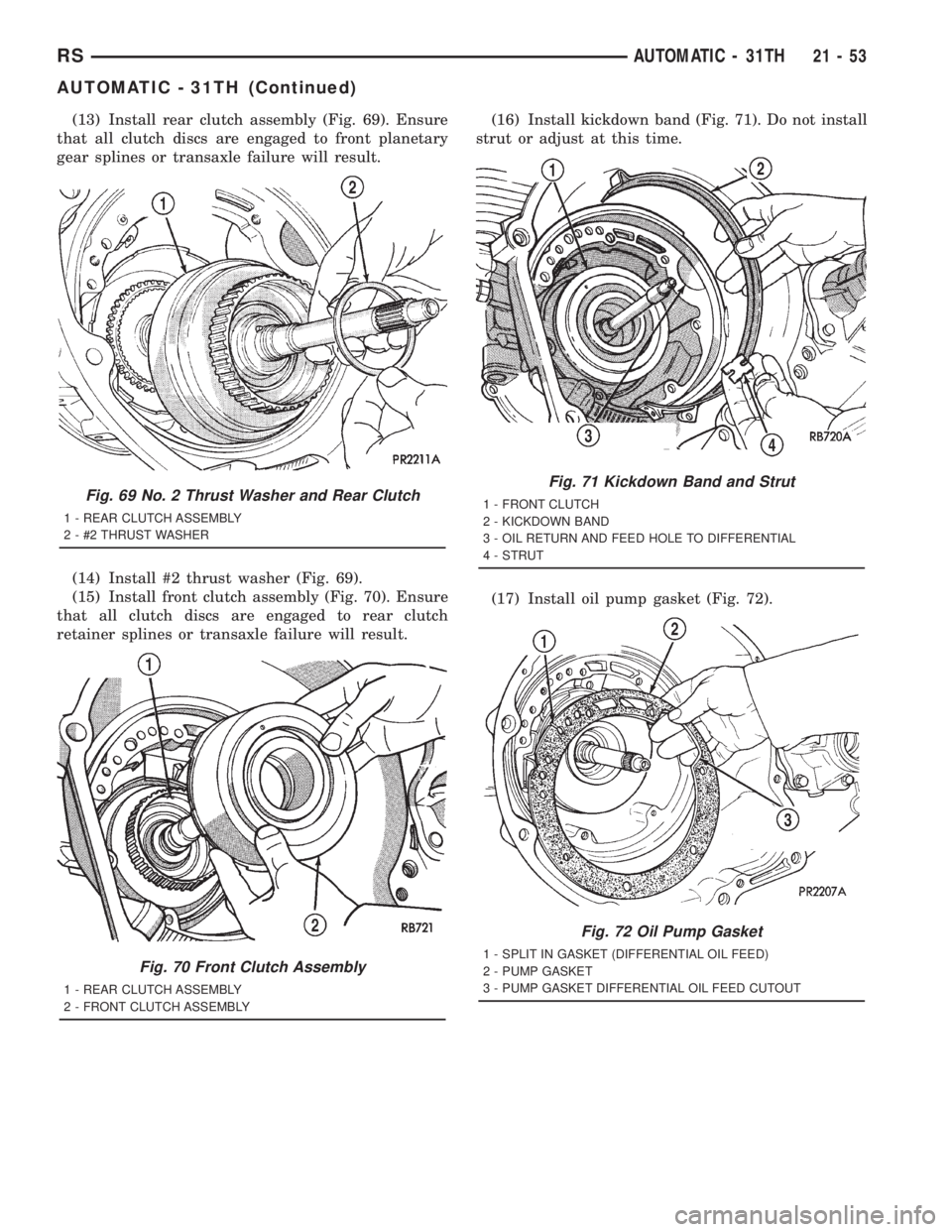
(13) Install rear clutch assembly (Fig. 69). Ensure
that all clutch discs are engaged to front planetary
gear splines or transaxle failure will result.
(14) Install #2 thrust washer (Fig. 69).
(15) Install front clutch assembly (Fig. 70). Ensure
that all clutch discs are engaged to rear clutch
retainer splines or transaxle failure will result.(16) Install kickdown band (Fig. 71). Do not install
strut or adjust at this time.
(17) Install oil pump gasket (Fig. 72).
Fig. 69 No. 2 Thrust Washer and Rear Clutch
1 - REAR CLUTCH ASSEMBLY
2 - #2 THRUST WASHER
Fig. 70 Front Clutch Assembly
1 - REAR CLUTCH ASSEMBLY
2 - FRONT CLUTCH ASSEMBLY
Fig. 71 Kickdown Band and Strut
1 - FRONT CLUTCH
2 - KICKDOWN BAND
3 - OIL RETURN AND FEED HOLE TO DIFFERENTIAL
4 - STRUT
Fig. 72 Oil Pump Gasket
1 - SPLIT IN GASKET (DIFFERENTIAL OIL FEED)
2 - PUMP GASKET
3 - PUMP GASKET DIFFERENTIAL OIL FEED CUTOUT
RSAUTOMATIC - 31TH21-53
AUTOMATIC - 31TH (Continued)
Page 3018 of 4284
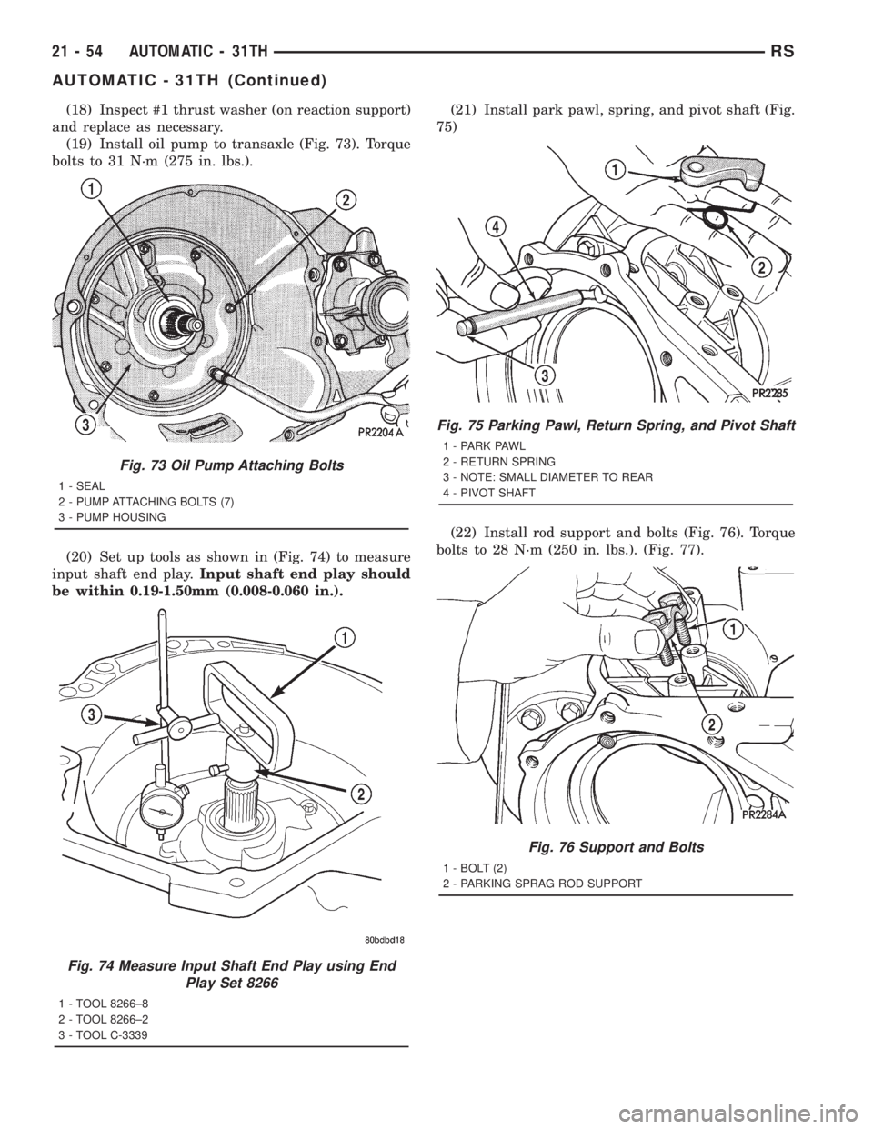
(18) Inspect #1 thrust washer (on reaction support)
and replace as necessary.
(19) Install oil pump to transaxle (Fig. 73). Torque
bolts to 31 N´m (275 in. lbs.).
(20) Set up tools as shown in (Fig. 74) to measure
input shaft end play.Input shaft end play should
be within 0.19-1.50mm (0.008-0.060 in.).(21) Install park pawl, spring, and pivot shaft (Fig.
75)
(22) Install rod support and bolts (Fig. 76). Torque
bolts to 28 N´m (250 in. lbs.). (Fig. 77).
Fig. 73 Oil Pump Attaching Bolts
1 - SEAL
2 - PUMP ATTACHING BOLTS (7)
3 - PUMP HOUSING
Fig. 74 Measure Input Shaft End Play using End
Play Set 8266
1 - TOOL 8266±8
2 - TOOL 8266±2
3 - TOOL C-3339
Fig. 75 Parking Pawl, Return Spring, and Pivot Shaft
1 - PARK PAWL
2 - RETURN SPRING
3 - NOTE: SMALL DIAMETER TO REAR
4 - PIVOT SHAFT
Fig. 76 Support and Bolts
1 - BOLT (2)
2 - PARKING SPRAG ROD SUPPORT
21 - 54 AUTOMATIC - 31THRS
AUTOMATIC - 31TH (Continued)
Page 3019 of 4284
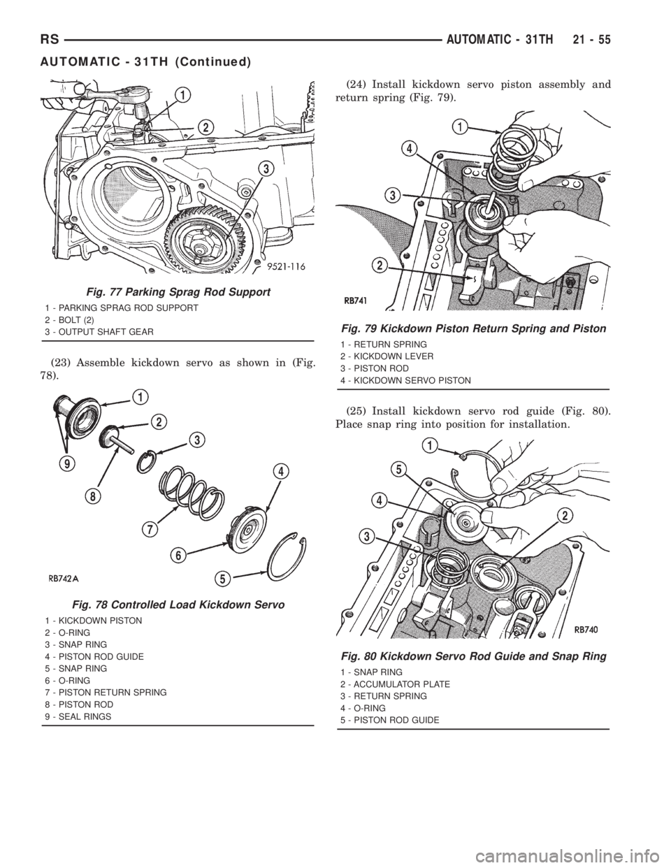
(23) Assemble kickdown servo as shown in (Fig.
78).(24) Install kickdown servo piston assembly and
return spring (Fig. 79).
(25) Install kickdown servo rod guide (Fig. 80).
Place snap ring into position for installation.
Fig. 77 Parking Sprag Rod Support
1 - PARKING SPRAG ROD SUPPORT
2 - BOLT (2)
3 - OUTPUT SHAFT GEAR
Fig. 78 Controlled Load Kickdown Servo
1 - KICKDOWN PISTON
2 - O-RING
3 - SNAP RING
4 - PISTON ROD GUIDE
5 - SNAP RING
6 - O-RING
7 - PISTON RETURN SPRING
8 - PISTON ROD
9 - SEAL RINGS
Fig. 79 Kickdown Piston Return Spring and Piston
1 - RETURN SPRING
2 - KICKDOWN LEVER
3 - PISTON ROD
4 - KICKDOWN SERVO PISTON
Fig. 80 Kickdown Servo Rod Guide and Snap Ring
1 - SNAP RING
2 - ACCUMULATOR PLATE
3 - RETURN SPRING
4 - O-RING
5 - PISTON ROD GUIDE
RSAUTOMATIC - 31TH21-55
AUTOMATIC - 31TH (Continued)
Page 3020 of 4284
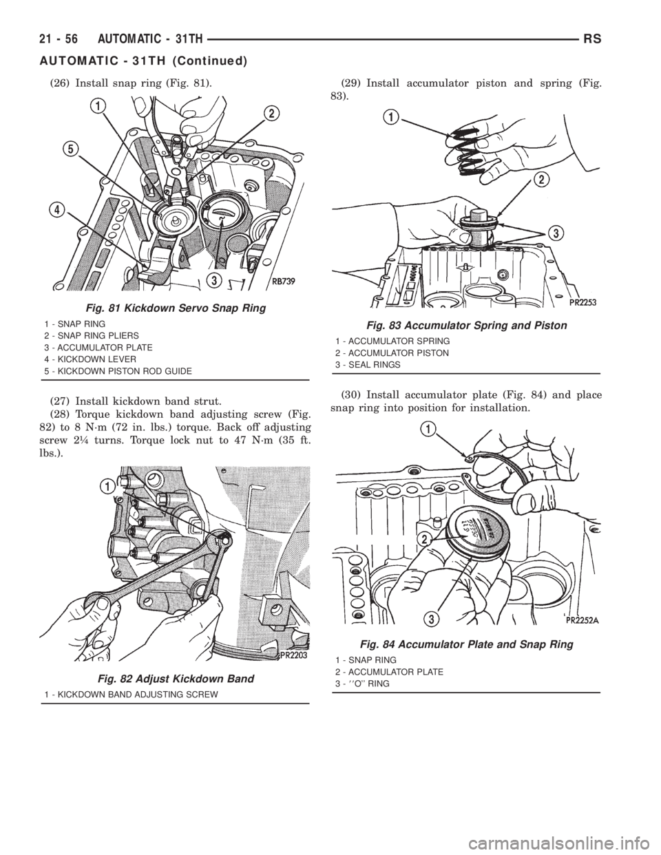
(26) Install snap ring (Fig. 81).
(27) Install kickdown band strut.
(28) Torque kickdown band adjusting screw (Fig.
82) to 8 N´m (72 in. lbs.) torque. Back off adjusting
screw 2ò turns. Torque lock nut to 47 N´m (35 ft.
lbs.).(29) Install accumulator piston and spring (Fig.
83).
(30) Install accumulator plate (Fig. 84) and place
snap ring into position for installation.
Fig. 81 Kickdown Servo Snap Ring
1 - SNAP RING
2 - SNAP RING PLIERS
3 - ACCUMULATOR PLATE
4 - KICKDOWN LEVER
5 - KICKDOWN PISTON ROD GUIDE
Fig. 82 Adjust Kickdown Band
1 - KICKDOWN BAND ADJUSTING SCREW
Fig. 83 Accumulator Spring and Piston
1 - ACCUMULATOR SPRING
2 - ACCUMULATOR PISTON
3 - SEAL RINGS
Fig. 84 Accumulator Plate and Snap Ring
1 - SNAP RING
2 - ACCUMULATOR PLATE
3-88O'' RING
21 - 56 AUTOMATIC - 31THRS
AUTOMATIC - 31TH (Continued)