CHRYSLER VOYAGER 2001 Service Manual
Manufacturer: CHRYSLER, Model Year: 2001, Model line: VOYAGER, Model: CHRYSLER VOYAGER 2001Pages: 4284, PDF Size: 83.53 MB
Page 3261 of 4284
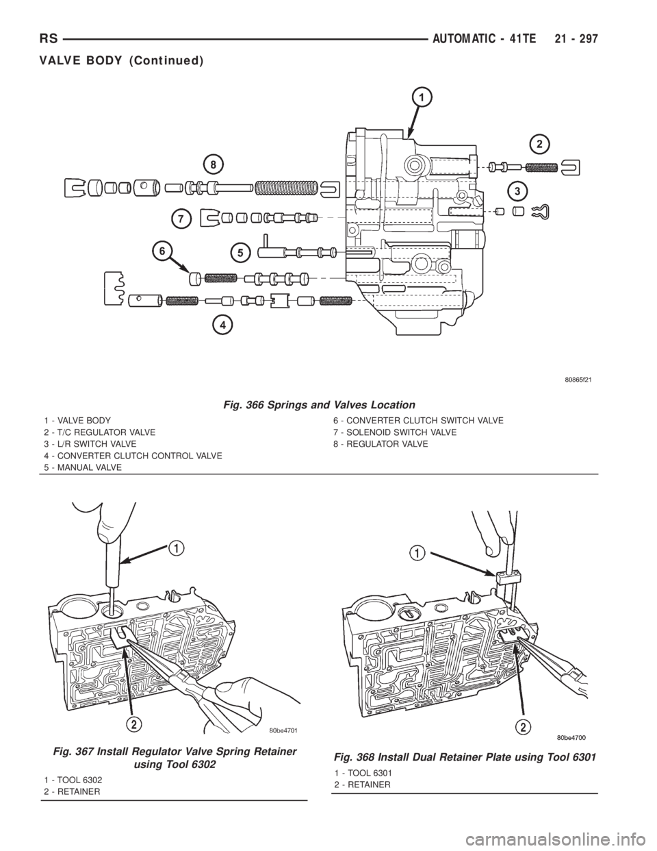
Fig. 366 Springs and Valves Location
1 - VALVE BODY
2 - T/C REGULATOR VALVE
3 - L/R SWITCH VALVE
4 - CONVERTER CLUTCH CONTROL VALVE
5 - MANUAL VALVE6 - CONVERTER CLUTCH SWITCH VALVE
7 - SOLENOID SWITCH VALVE
8 - REGULATOR VALVE
Fig. 367 Install Regulator Valve Spring Retainer
using Tool 6302
1 - TOOL 6302
2 - RETAINER
Fig. 368 Install Dual Retainer Plate using Tool 6301
1 - TOOL 6301
2 - RETAINER
RSAUTOMATIC - 41TE21 - 297
VALVE BODY (Continued)
Page 3262 of 4284
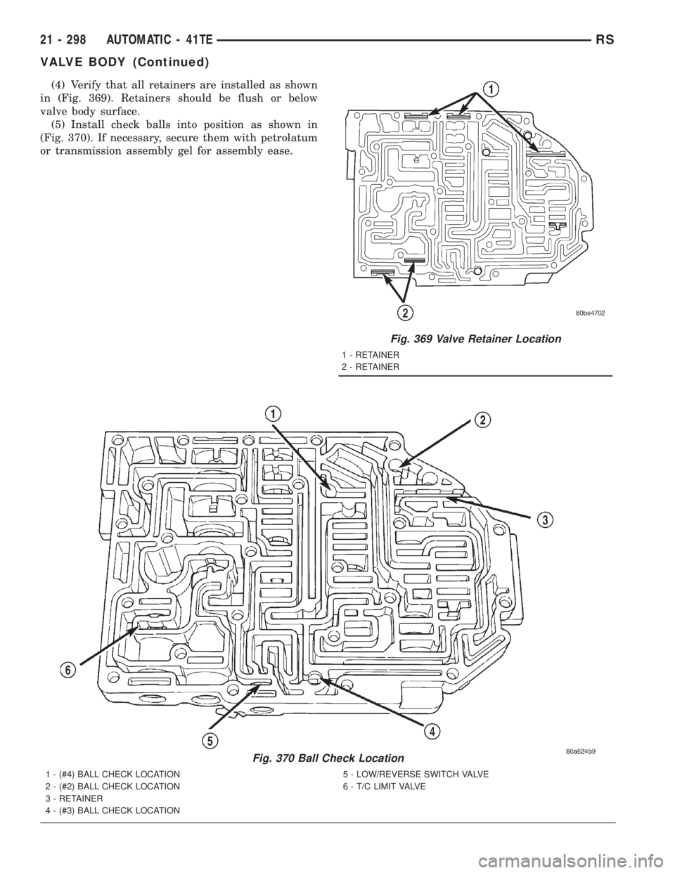
(4) Verify that all retainers are installed as shown
in (Fig. 369). Retainers should be flush or below
valve body surface.
(5) Install check balls into position as shown in
(Fig. 370). If necessary, secure them with petrolatum
or transmission assembly gel for assembly ease.
Fig. 369 Valve Retainer Location
1 - RETAINER
2 - RETAINER
Fig. 370 Ball Check Location
1 - (#4) BALL CHECK LOCATION
2 - (#2) BALL CHECK LOCATION
3 - RETAINER
4 - (#3) BALL CHECK LOCATION5 - LOW/REVERSE SWITCH VALVE
6 - T/C LIMIT VALVE
21 - 298 AUTOMATIC - 41TERS
VALVE BODY (Continued)
Page 3263 of 4284
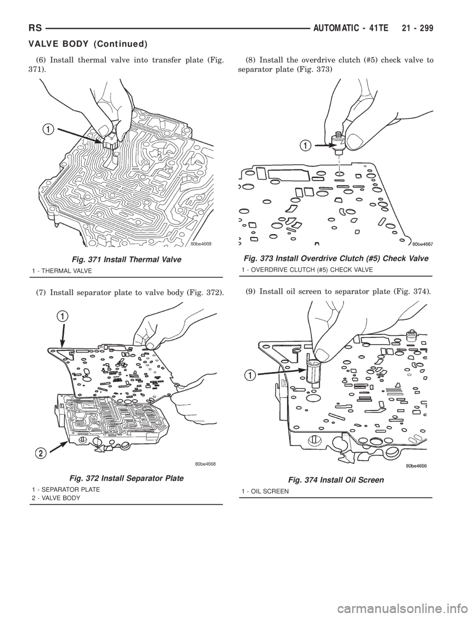
(6) Install thermal valve into transfer plate (Fig.
371).
(7) Install separator plate to valve body (Fig. 372).(8) Install the overdrive clutch (#5) check valve to
separator plate (Fig. 373)
(9) Install oil screen to separator plate (Fig. 374).
Fig. 371 Install Thermal Valve
1 - THERMAL VALVE
Fig. 372 Install Separator Plate
1 - SEPARATOR PLATE
2 - VALVE BODY
Fig. 373 Install Overdrive Clutch (#5) Check Valve
1 - OVERDRIVE CLUTCH (#5) CHECK VALVE
Fig. 374 Install Oil Screen
1 - OIL SCREEN
RSAUTOMATIC - 41TE21 - 299
VALVE BODY (Continued)
Page 3264 of 4284
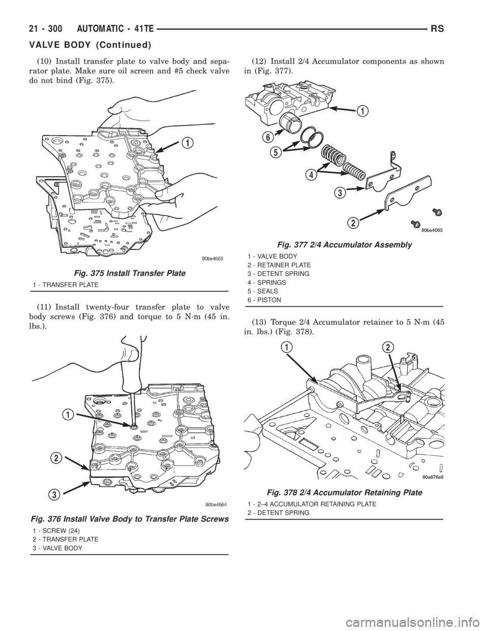
(10) Install transfer plate to valve body and sepa-
rator plate. Make sure oil screen and #5 check valve
do not bind (Fig. 375).
(11) Install twenty-four transfer plate to valve
body screws (Fig. 376) and torque to 5 N´m (45 in.
lbs.).(12) Install 2/4 Accumulator components as shown
in (Fig. 377).
(13) Torque 2/4 Accumulator retainer to 5 N´m (45
in. lbs.) (Fig. 378).
Fig. 375 Install Transfer Plate
1 - TRANSFER PLATE
Fig. 376 Install Valve Body to Transfer Plate Screws
1 - SCREW (24)
2 - TRANSFER PLATE
3 - VALVE BODY
Fig. 377 2/4 Accumulator Assembly
1 - VALVE BODY
2 - RETAINER PLATE
3 - DETENT SPRING
4 - SPRINGS
5 - SEALS
6 - PISTON
Fig. 378 2/4 Accumulator Retaining Plate
1 - 2±4 ACCUMULATOR RETAINING PLATE
2 - DETENT SPRING
21 - 300 AUTOMATIC - 41TERS
VALVE BODY (Continued)
Page 3265 of 4284
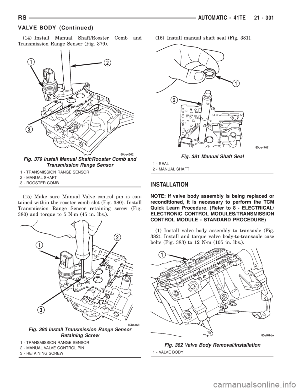
(14) Install Manual Shaft/Rooster Comb and
Transmission Range Sensor (Fig. 379).
(15) Make sure Manual Valve control pin is con-
tained within the rooster comb slot (Fig. 380). Install
Transmission Range Sensor retaining screw (Fig.
380) and torque to 5 N´m (45 in. lbs.).(16) Install manual shaft seal (Fig. 381).
INSTALLATION
NOTE: If valve body assembly is being replaced or
reconditioned, it is necessary to perform the TCM
Quick Learn Procedure. (Refer to 8 - ELECTRICAL/
ELECTRONIC CONTROL MODULES/TRANSMISSION
CONTROL MODULE - STANDARD PROCEDURE)
(1) Install valve body assembly to transaxle (Fig.
382). Install and torque valve body-to-transaxle case
bolts (Fig. 383) to 12 N´m (105 in. lbs.).
Fig. 379 Install Manual Shaft/Rooster Comb and
Transmission Range Sensor
1 - TRANSMISSION RANGE SENSOR
2 - MANUAL SHAFT
3 - ROOSTER COMB
Fig. 380 Install Transmission Range Sensor
Retaining Screw
1 - TRANSMISSION RANGE SENSOR
2 - MANUAL VALVE CONTROL PIN
3 - RETAINING SCREW
Fig. 381 Manual Shaft Seal
1 - SEAL
2 - MANUAL SHAFT
Fig. 382 Valve Body Removal/Installation
1 - VALVE BODY
RSAUTOMATIC - 41TE21 - 301
VALVE BODY (Continued)
Page 3266 of 4284
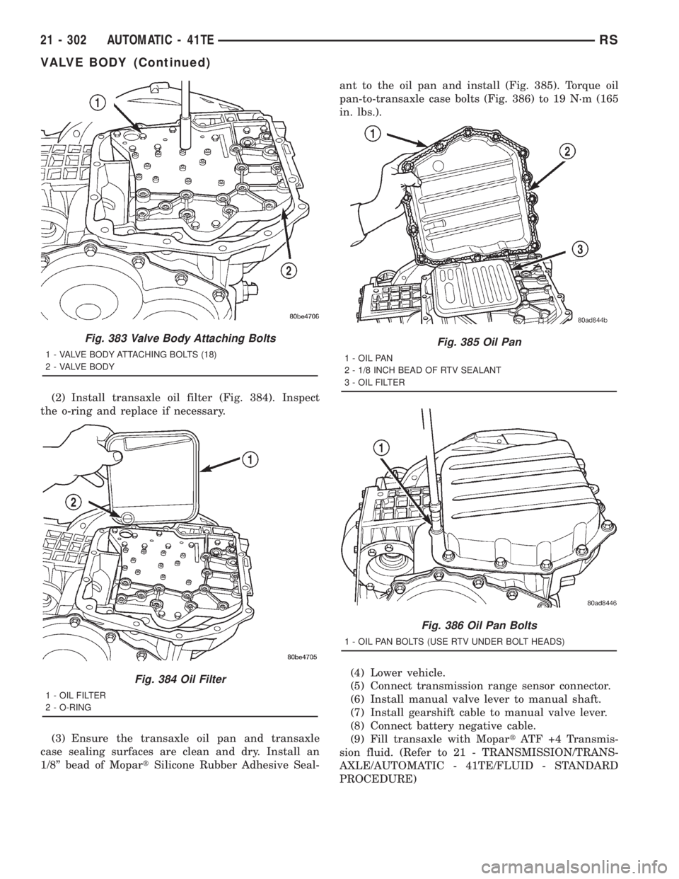
(2) Install transaxle oil filter (Fig. 384). Inspect
the o-ring and replace if necessary.
(3) Ensure the transaxle oil pan and transaxle
case sealing surfaces are clean and dry. Install an
1/8º bead of MopartSilicone Rubber Adhesive Seal-ant to the oil pan and install (Fig. 385). Torque oil
pan-to-transaxle case bolts (Fig. 386) to 19 N´m (165
in. lbs.).
(4) Lower vehicle.
(5) Connect transmission range sensor connector.
(6) Install manual valve lever to manual shaft.
(7) Install gearshift cable to manual valve lever.
(8) Connect battery negative cable.
(9) Fill transaxle with MopartATF +4 Transmis-
sion fluid. (Refer to 21 - TRANSMISSION/TRANS-
AXLE/AUTOMATIC - 41TE/FLUID - STANDARD
PROCEDURE)
Fig. 383 Valve Body Attaching Bolts
1 - VALVE BODY ATTACHING BOLTS (18)
2 - VALVE BODY
Fig. 384 Oil Filter
1 - OIL FILTER
2 - O-RING
Fig. 385 Oil Pan
1 - OIL PAN
2 - 1/8 INCH BEAD OF RTV SEALANT
3 - OIL FILTER
Fig. 386 Oil Pan Bolts
1 - OIL PAN BOLTS (USE RTV UNDER BOLT HEADS)
21 - 302 AUTOMATIC - 41TERS
VALVE BODY (Continued)
Page 3267 of 4284
T850 MANUAL TRANSAXLE
TABLE OF CONTENTS
page
T850 MANUAL TRANSAXLE.................1
T850 MANUAL TRANSAXLE
TABLE OF CONTENTS
page page
T850 MANUAL TRANSAXLE
DESCRIPTION............................2
OPERATION.............................4
DIAGNOSIS AND TESTING.................11
DIAGNOSIS AND TESTING - COMMON
PROBLEM CAUSES.....................11
REMOVAL..............................11
DISASSEMBLY...........................17
ASSEMBLY.............................22
INSTALLATION...........................31
SPECIFICATIONS........................37
SPECIAL TOOLS.........................39
AXLE SEALS
REMOVAL..............................42
INSTALLATION...........................42
BACK-UP LAMP SWITCH
REMOVAL..............................43
INSTALLATION...........................43
DIFFERENTIAL
DESCRIPTION...........................43
OPERATION.............................43
DISASSEMBLY...........................44
ASSEMBLY.............................47
ADJUSTMENTS..........................50
FLUID
STANDARD PROCEDURE..................52
STANDARD PROCEDURE - FLUID LEVEL
CHECK...............................52
STANDARD PROCEDURE - FLUID DRAIN
AND FILL.............................53
GEARSHIFT BOOT
REMOVAL..............................53
INSTALLATION...........................53
GEARSHIFT CABLE - CROSSOVER
REMOVAL..............................54INSTALLATION...........................56
ADJUSTMENTS..........................60
GEARSHIFT CABLE - SELECTOR
REMOVAL..............................61
INSTALLATION...........................64
GEARSHIFT KNOB
REMOVAL..............................67
INSTALLATION...........................67
GEARSHIFT MECHANISM
REMOVAL..............................68
INSTALLATION...........................70
INPUT SHAFT
DESCRIPTION...........................73
DISASSEMBLY...........................74
ASSEMBLY.............................77
INTERMEDIATE SHAFT
DESCRIPTION...........................81
DISASSEMBLY...........................81
ASSEMBLY.............................88
SHIFT COVER
DESCRIPTION...........................94
SHIFT FORK AND SHAFT
DESCRIPTION...........................95
SYNCHRONIZER
DESCRIPTION...........................95
DISASSEMBLY...........................95
CLEANING..............................95
INSPECTION............................95
ASSEMBLY.............................95
VEHICLE SPEED SENSOR
REMOVAL..............................96
INSTALLATION...........................96
RGT850 MANUAL TRANSAXLE21a-1
Page 3268 of 4284
T850 MANUAL TRANSAXLE
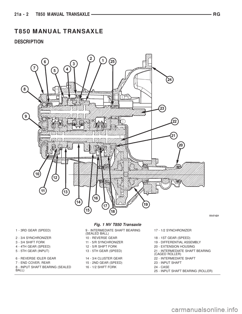
DESCRIPTION
Fig. 1 NV T850 Transaxle
1 - 3RD GEAR (SPEED) 9 - INTERMEDIATE SHAFT BEARING
(SEALED BALL)17 - 1/2 SYNCHRONIZER
2 - 3/4 SYNCHRONIZER 10 - REVERSE GEAR 18 - 1ST GEAR (SPEED)
3 - 3/4 SHIFT FORK 11 - 5/R SYNCHRONIZER 19 - DIFFERENTIAL ASSEMBLY
4 - 4TH GEAR (SPEED) 12 - 5/R SHIFT FORK 20 - EXTENSION HOUSING
5 - 5TH GEAR (INPUT) 13 - 5TH GEAR (SPEED) 21 - INTERMEDIATE SHAFT BEARING
(CAGED ROLLER)
6 - REVERSE IDLER GEAR 14 - 3/4 CLUSTER GEAR 22 - INTERMEDIATE SHAFT
7 - END COVER, REAR 15 - 2ND GEAR (SPEED) 23 - INPUT SHAFT
8 - INPUT SHAFT BEARING (SEALED
BALL)16 - 1/2 SHIFT FORK 24 - CASE
25 - INPUT SHAFT BEARING (ROLLER)
21a - 2 T850 MANUAL TRANSAXLERG
Page 3269 of 4284
The NV T850 5-speed transaxle (Fig. 1) is a con-
stant-mesh manual transaxle that is synchronized in
all gear ranges, including reverse.
The transaxle consists of three major sub-assem-
blies: the input shaft, intermediate shaft, and differ-
ential assembly. The transaxle shift system consists
of a mechanical shift cover, rails, forks, and cables.
The unique design of this shift system provides a
higher mechanical advantage, resulting in less fric-
tion and lower shift cable loads for smoother, more
positive operation.
The NV T850 transaxle is available with the 2.4L
Gas and 2.5L Turbo Diesel engine options. Unique
gearing tailored to the performance characteristics of
each engine provides optimum driveability, gradabil-
ity, and acceleration. The gear ratios are as follows:
GEARRATIO
(2.4L Gas)RATIO
(2.5L TD)
1st 3.65 3.46
2nd 2.07 2.05
3rd 1.39 1.37
4th 1.03 0.97
5th 0.83 0.76
Reverse 3.47 3.47
Final Drive
Ratio3.77 3.53
Overall Top
Gear3.12 2.66
TRANSAXLE IDENTIFICATION
NOTE: Since transaxles use unique gear ratios for
each of the two engine applications, it is imperative
that the transaxle is properly identified, and the cor-
rect transaxle assembly number is used when
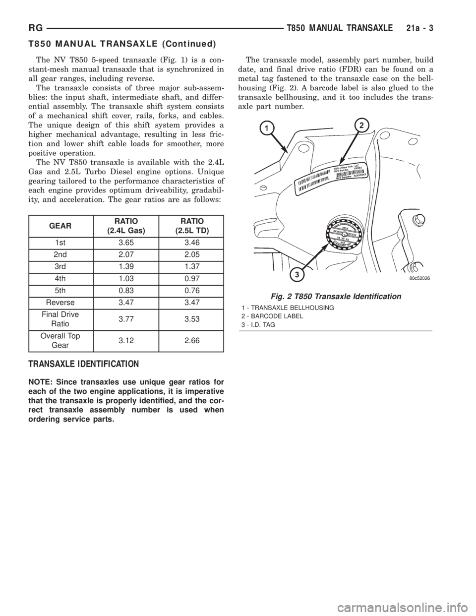
ordering service parts.The transaxle model, assembly part number, build
date, and final drive ratio (FDR) can be found on a
metal tag fastened to the transaxle case on the bell-
housing (Fig. 2). A barcode label is also glued to the
transaxle bellhousing, and it too includes the trans-
axle part number.
Fig. 2 T850 Transaxle Identification
1 - TRANSAXLE BELLHOUSING
2 - BARCODE LABEL
3 - I.D. TAG
RGT850 MANUAL TRANSAXLE21a-3
T850 MANUAL TRANSAXLE (Continued)
Page 3270 of 4284
OPERATION
NEUTRAL
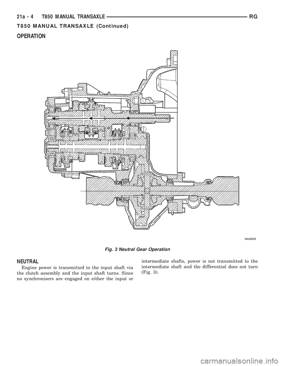
Engine power is transmitted to the input shaft via
the clutch assembly and the input shaft turns. Since
no synchronizers are engaged on either the input orintermediate shafts, power is not transmitted to the
intermediate shaft and the differential does not turn
(Fig. 3).
Fig. 3 Neutral Gear Operation
21a - 4 T850 MANUAL TRANSAXLERG
T850 MANUAL TRANSAXLE (Continued)