CHRYSLER VOYAGER 2001 Service Manual
VOYAGER 2001
CHRYSLER
CHRYSLER
https://www.carmanualsonline.info/img/25/56872/w960_56872-0.png
CHRYSLER VOYAGER 2001 Service Manual
Trending: oil viscosity, recommended oil, key fob, fuel type, homelink, traction control, dead battery
Page 3341 of 4284
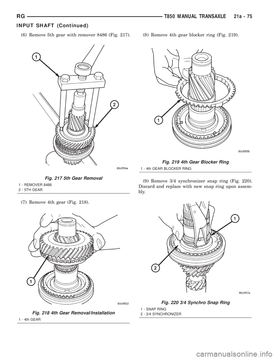
(6) Remove 5th gear with remover 8486 (Fig. 217).
(7) Remove 4th gear (Fig. 218).(8) Remove 4th gear blocker ring (Fig. 219).
(9) Remove 3/4 synchronizer snap ring (Fig. 220).
Discard and replace with new snap ring upon assem-
bly.
Fig. 217 5th Gear Removal
1 - REMOVER 8486
2 - 5TH GEAR
Fig. 218 4th Gear Removal/Installation
1 - 4th GEAR
Fig. 219 4th Gear Blocker Ring
1 - 4th GEAR BLOCKER RING
Fig. 220 3/4 Synchro Snap Ring
1 - SNAP RING
2 - 3/4 SYNCHRONIZER
RGT850 MANUAL TRANSAXLE21a-75
INPUT SHAFT (Continued)
Page 3342 of 4284
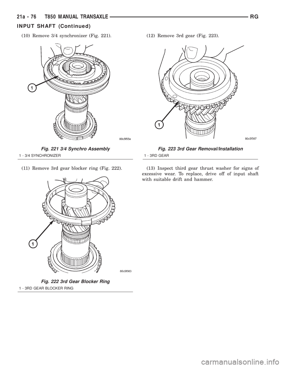
(10) Remove 3/4 synchronizer (Fig. 221).
(11) Remove 3rd gear blocker ring (Fig. 222).(12) Remove 3rd gear (Fig. 223).
(13) Inspect third gear thrust washer for signs of
excessive wear. To replace, drive off of input shaft
with suitable drift and hammer.
Fig. 221 3/4 Synchro Assembly
1 - 3/4 SYNCHRONIZER
Fig. 222 3rd Gear Blocker Ring
1 - 3RD GEAR BLOCKER RING
Fig. 223 3rd Gear Removal/Installation
1 - 3RD GEAR
21a - 76 T850 MANUAL TRANSAXLERG
INPUT SHAFT (Continued)
Page 3343 of 4284
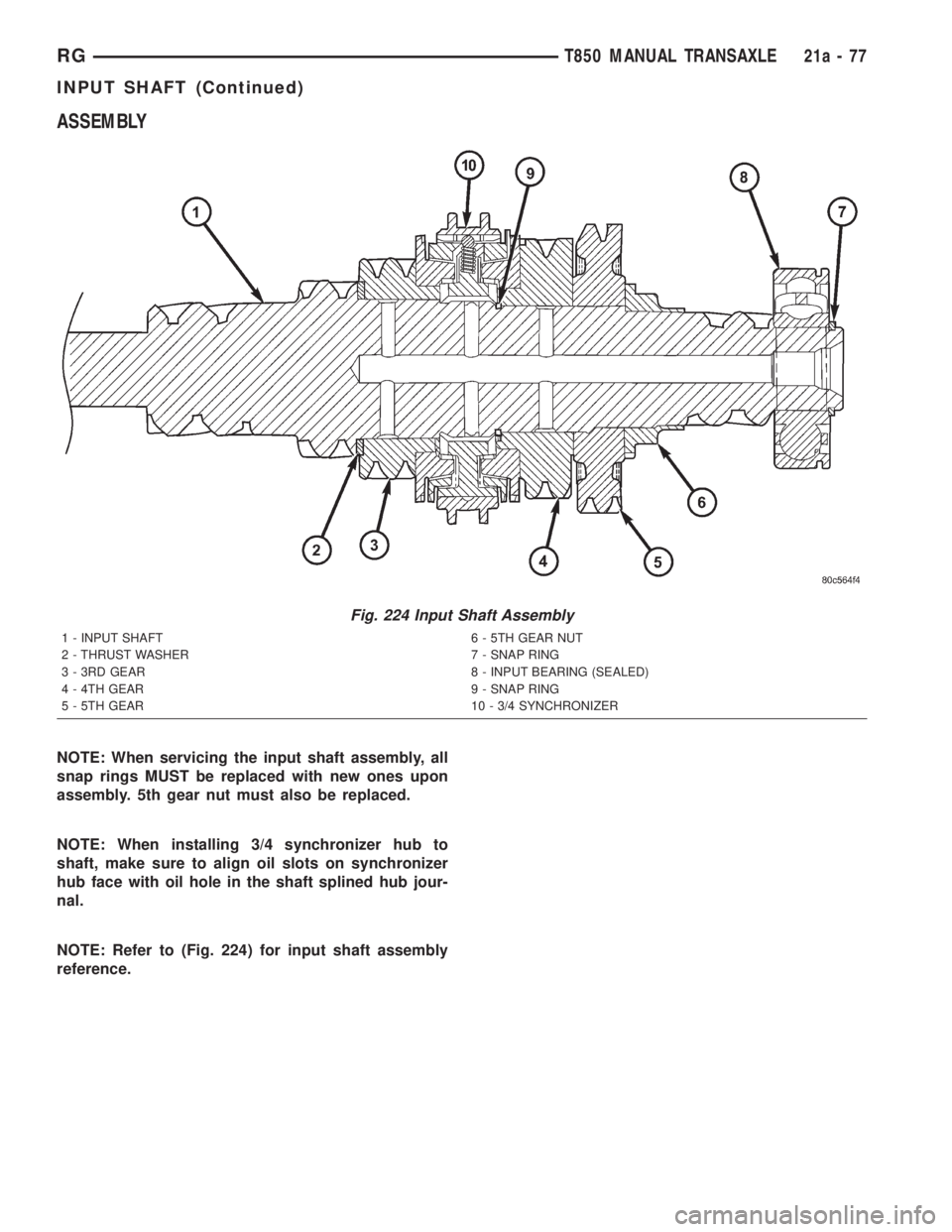
ASSEMBLY
NOTE: When servicing the input shaft assembly, all
snap rings MUST be replaced with new ones upon
assembly. 5th gear nut must also be replaced.
NOTE: When installing 3/4 synchronizer hub to
shaft, make sure to align oil slots on synchronizer
hub face with oil hole in the shaft splined hub jour-
nal.
NOTE: Refer to (Fig. 224) for input shaft assembly
reference.
Fig. 224 Input Shaft Assembly
1 - INPUT SHAFT 6 - 5TH GEAR NUT
2 - THRUST WASHER 7 - SNAP RING
3 - 3RD GEAR 8 - INPUT BEARING (SEALED)
4 - 4TH GEAR 9 - SNAP RING
5 - 5TH GEAR 10 - 3/4 SYNCHRONIZER
RGT850 MANUAL TRANSAXLE21a-77
INPUT SHAFT (Continued)
Page 3344 of 4284
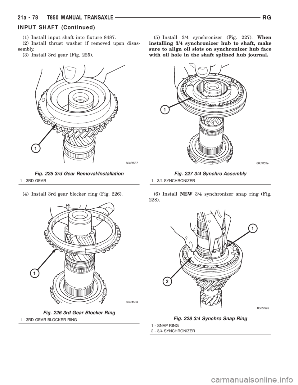
(1) Install input shaft into fixture 8487.
(2) Install thrust washer if removed upon disas-
sembly.
(3) Install 3rd gear (Fig. 225).
(4) Install 3rd gear blocker ring (Fig. 226).(5) Install 3/4 synchronizer (Fig. 227).When
installing 3/4 synchronizer hub to shaft, make
sure to align oil slots on synchronizer hub face
with oil hole in the shaft splined hub journal.
(6) InstallNEW3/4 synchronizer snap ring (Fig.
228).
Fig. 225 3rd Gear Removal/Installation
1 - 3RD GEAR
Fig. 226 3rd Gear Blocker Ring
1 - 3RD GEAR BLOCKER RING
Fig. 227 3/4 Synchro Assembly
1 - 3/4 SYNCHRONIZER
Fig. 228 3/4 Synchro Snap Ring
1 - SNAP RING
2 - 3/4 SYNCHRONIZER
21a - 78 T850 MANUAL TRANSAXLERG
INPUT SHAFT (Continued)
Page 3345 of 4284
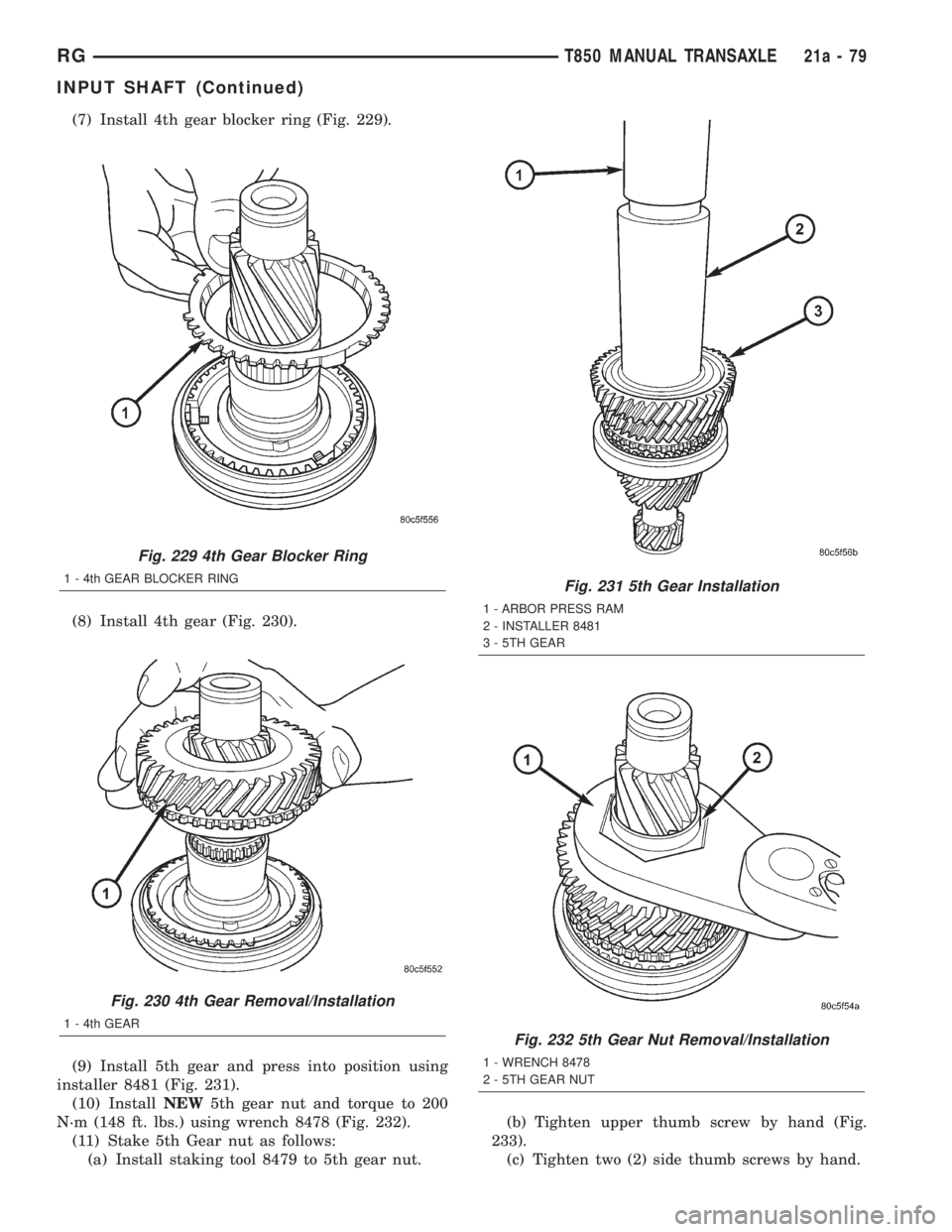
(7) Install 4th gear blocker ring (Fig. 229).
(8) Install 4th gear (Fig. 230).
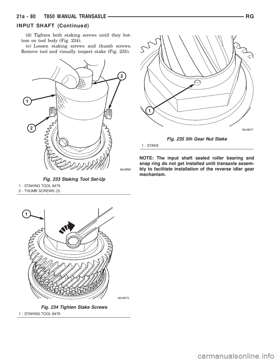
(9) Install 5th gear and press into position using
installer 8481 (Fig. 231).
(10) InstallNEW5th gear nut and torque to 200
N´m (148 ft. lbs.) using wrench 8478 (Fig. 232).
(11) Stake 5th Gear nut as follows:
(a) Install staking tool 8479 to 5th gear nut.(b) Tighten upper thumb screw by hand (Fig.
233).
(c) Tighten two (2) side thumb screws by hand.
Fig. 229 4th Gear Blocker Ring
1 - 4th GEAR BLOCKER RING
Fig. 230 4th Gear Removal/Installation
1 - 4th GEAR
Fig. 231 5th Gear Installation
1 - ARBOR PRESS RAM
2 - INSTALLER 8481
3 - 5TH GEAR
Fig. 232 5th Gear Nut Removal/Installation
1 - WRENCH 8478
2 - 5TH GEAR NUT
RGT850 MANUAL TRANSAXLE21a-79
INPUT SHAFT (Continued)
Page 3346 of 4284
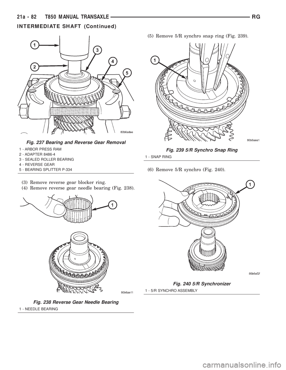
(d) Tighten both staking screws until they bot-
tom on tool body (Fig. 234).
(e) Loosen staking screws and thumb screws.
Remove tool and visually inspect stake (Fig. 235).
NOTE: The input shaft sealed roller bearing and
snap ring do not get installed until transaxle assem-
bly to facilitate installation of the reverse idler gear
mechanism.
Fig. 233 Staking Tool Set-Up
1 - STAKING TOOL 8479
2 - THUMB SCREWS (3)
Fig. 234 Tighten Stake Screws
1 - STAKING TOOL 8479
Fig. 235 5th Gear Nut Stake
1-STAKE
21a - 80 T850 MANUAL TRANSAXLERG
INPUT SHAFT (Continued)
Page 3347 of 4284
INTERMEDIATE SHAFT
DESCRIPTION
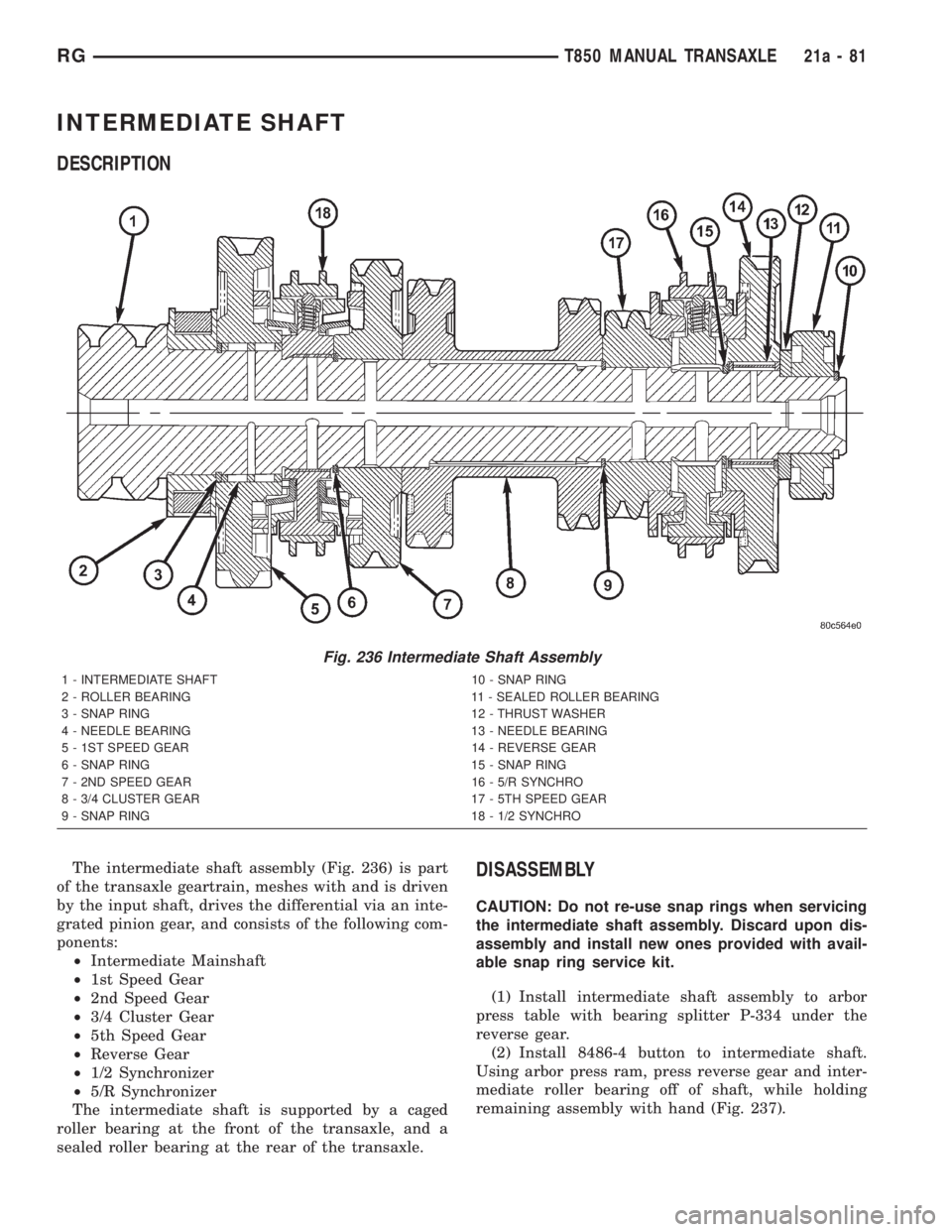
The intermediate shaft assembly (Fig. 236) is part
of the transaxle geartrain, meshes with and is driven
by the input shaft, drives the differential via an inte-
grated pinion gear, and consists of the following com-
ponents:
²Intermediate Mainshaft
²1st Speed Gear
²2nd Speed Gear
²3/4 Cluster Gear
²5th Speed Gear
²Reverse Gear
²1/2 Synchronizer
²5/R Synchronizer
The intermediate shaft is supported by a caged
roller bearing at the front of the transaxle, and a
sealed roller bearing at the rear of the transaxle.DISASSEMBLY
CAUTION: Do not re-use snap rings when servicing
the intermediate shaft assembly. Discard upon dis-
assembly and install new ones provided with avail-
able snap ring service kit.
(1) Install intermediate shaft assembly to arbor
press table with bearing splitter P-334 under the
reverse gear.
(2) Install 8486-4 button to intermediate shaft.
Using arbor press ram, press reverse gear and inter-
mediate roller bearing off of shaft, while holding
remaining assembly with hand (Fig. 237).
Fig. 236 Intermediate Shaft Assembly
1 - INTERMEDIATE SHAFT 10 - SNAP RING
2 - ROLLER BEARING 11 - SEALED ROLLER BEARING
3 - SNAP RING 12 - THRUST WASHER
4 - NEEDLE BEARING 13 - NEEDLE BEARING
5 - 1ST SPEED GEAR 14 - REVERSE GEAR
6 - SNAP RING 15 - SNAP RING
7 - 2ND SPEED GEAR 16 - 5/R SYNCHRO
8 - 3/4 CLUSTER GEAR 17 - 5TH SPEED GEAR
9 - SNAP RING 18 - 1/2 SYNCHRO
RGT850 MANUAL TRANSAXLE21a-81
Page 3348 of 4284
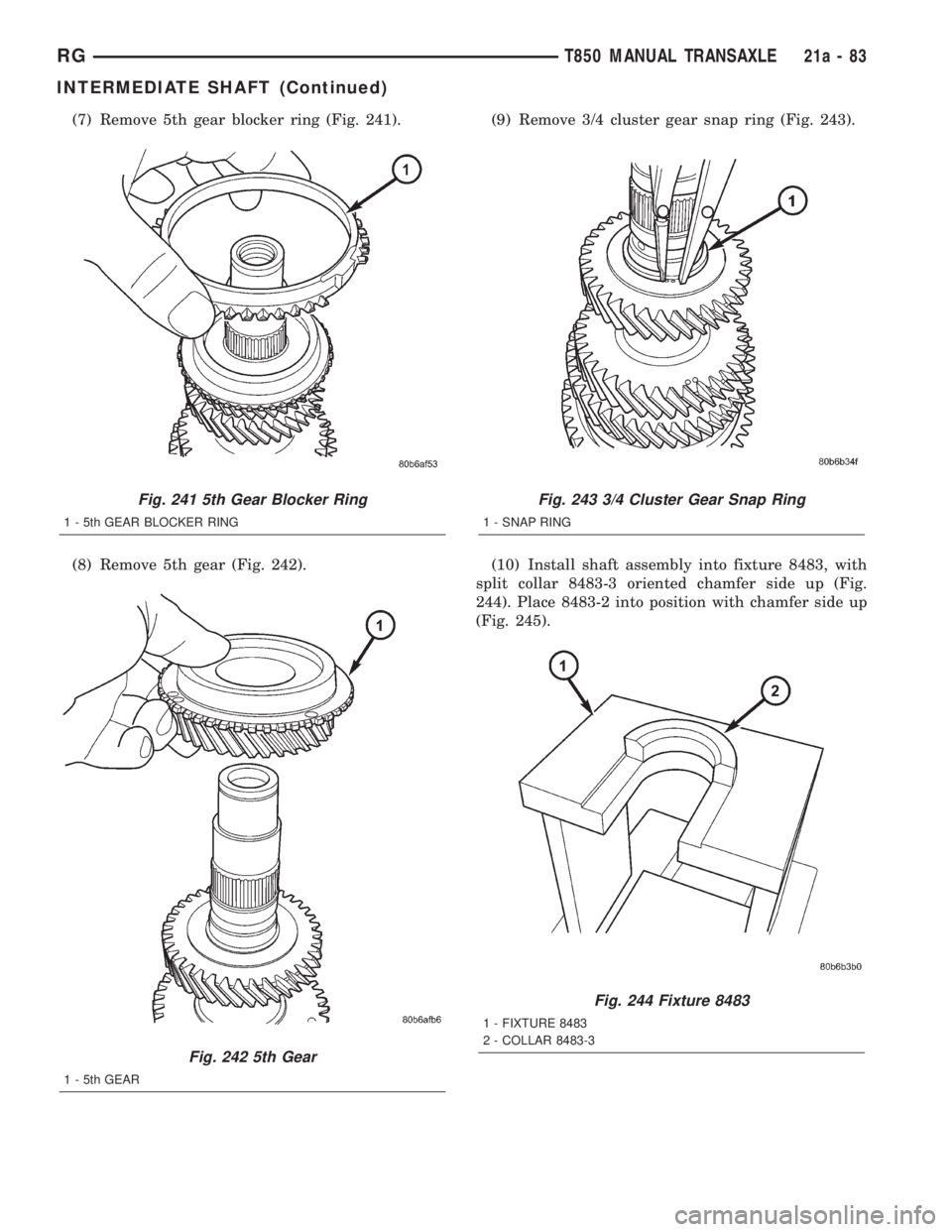
(3) Remove reverse gear blocker ring.
(4) Remove reverse gear needle bearing (Fig. 238).(5) Remove 5/R synchro snap ring (Fig. 239).
(6) Remove 5/R synchro (Fig. 240).
Fig. 237 Bearing and Reverse Gear Removal
1 - ARBOR PRESS RAM
2 - ADAPTER 8486-4
3 - SEALED ROLLER BEARING
4 - REVERSE GEAR
5 - BEARING SPLITTER P-334
Fig. 238 Reverse Gear Needle Bearing
1 - NEEDLE BEARING
Fig. 239 5/R Synchro Snap Ring
1 - SNAP RING
Fig. 240 5/R Synchronizer
1 - 5/R SYNCHRO ASSEMBLY
21a - 82 T850 MANUAL TRANSAXLERG
INTERMEDIATE SHAFT (Continued)
Page 3349 of 4284
(7) Remove 5th gear blocker ring (Fig. 241).
(8) Remove 5th gear (Fig. 242).(9) Remove 3/4 cluster gear snap ring (Fig. 243).
(10) Install shaft assembly into fixture 8483, with
split collar 8483-3 oriented chamfer side up (Fig.
244). Place 8483-2 into position with chamfer side up
(Fig. 245).
Fig. 241 5th Gear Blocker Ring
1 - 5th GEAR BLOCKER RING
Fig. 242 5th Gear
1 - 5th GEAR
Fig. 243 3/4 Cluster Gear Snap Ring
1 - SNAP RING
Fig. 244 Fixture 8483
1 - FIXTURE 8483
2 - COLLAR 8483-3
RGT850 MANUAL TRANSAXLE21a-83
INTERMEDIATE SHAFT (Continued)
Page 3350 of 4284
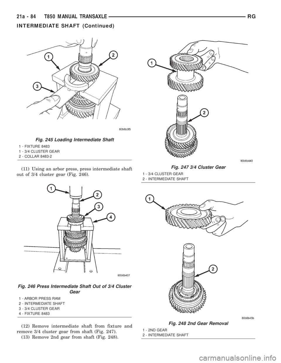
(11) Using an arbor press, press intermediate shaft
out of 3/4 cluster gear (Fig. 246).
(12) Remove intermediate shaft from fixture and
remove 3/4 cluster gear from shaft (Fig. 247).
(13) Remove 2nd gear from shaft (Fig. 248).
Fig. 245 Loading Intermediate Shaft
1 - FIXTURE 8483
1 - 3/4 CLUSTER GEAR
2 - COLLAR 8483-2
Fig. 246 Press Intermediate Shaft Out of 3/4 Cluster
Gear
1 - ARBOR PRESS RAM
2 - INTERMEDIATE SHAFT
3 - 3/4 CLUSTER GEAR
4 - FIXTURE 8483
Fig. 247 3/4 Cluster Gear
1 - 3/4 CLUSTER GEAR
2 - INTERMEDIATE SHAFT
Fig. 248 2nd Gear Removal
1 - 2ND GEAR
2 - INTERMEDIATE SHAFT
21a - 84 T850 MANUAL TRANSAXLERG
INTERMEDIATE SHAFT (Continued)
Trending: water pump, coolant, turn signal, ABS, transmission oil, spare tire, tires
