torque CHRYSLER VOYAGER 2004 Service Manual
[x] Cancel search | Manufacturer: CHRYSLER, Model Year: 2004, Model line: VOYAGER, Model: CHRYSLER VOYAGER 2004Pages: 2585, PDF Size: 62.54 MB
Page 1962 of 2585
(5) If the turning torque is within specifications,
remove tools. Setup is complete. (6) If turning torque is not within specifications
proceed with the following steps. (a) Remove differential bearing retainer from
the transaxle case. (b) Remove the bearing cup from the differential
bearing retainer using Tool 6062A. (c) Remove the existing shim from under the
cup. (d) Measure the existing shim.
(e) If the turning torque was too high when mea-
sured, install a 0.05 mm (0.002 inch) thinner shim.
If the turning torque is was too low, install a 0.05
mm (0.002 inch) thicker shim. Repeat until 5 to 18
inch-pounds turning torque is obtained. Oil Baffle
is not required to be installed when making shim
selection. (f) Install the proper shim under the bearing
cup. Make sure the oil baffle is installed properly in the bearing retainer, below the bearing shim
and cup.
(g) Install the differential bearing retainer using
Tool 5052 and C-4171. Seal the retainer to the
housing with MOPAR tAdhesive Sealant and
torque bolts to 28 N´m (250 in. lbs.).
(7) Using Tool L-4436A and an inch-pound torque
wrench, recheck the turning torque of the differential
(Fig. 186). The turning torque should be
between 5 and 18 inch-pounds. Shim thickness need be determined only if any of
the following parts are replaced: ² Transaxle case
² Differential carrier
² Differential bearing retainer
² Extension housing
² Differential bearing cups and cones
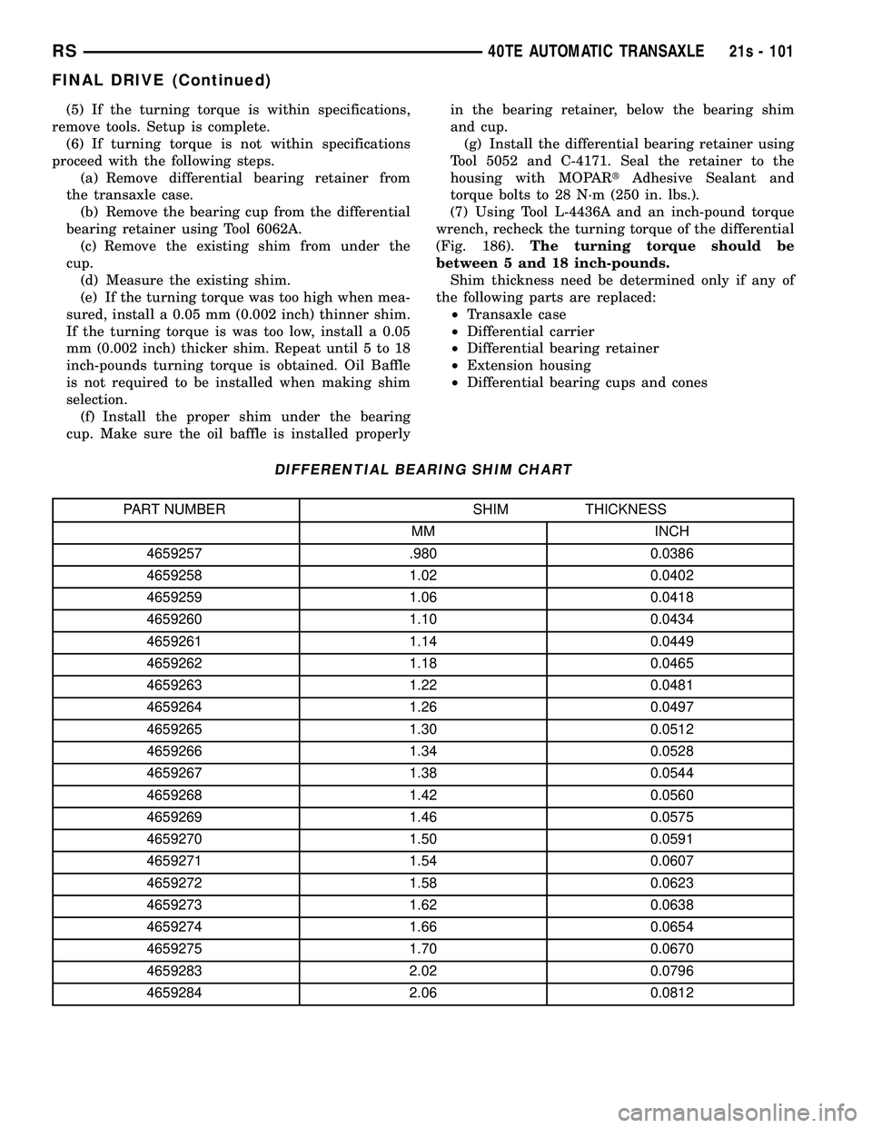
DIFFERENTIAL BEARING SHIM CHART
PART NUMBER SHIM THICKNESS
MM INCH
4659257 .980 0.0386
4659258 1.02 0.0402
4659259 1.06 0.0418
4659260 1.10 0.0434
4659261 1.14 0.0449
4659262 1.18 0.0465
4659263 1.22 0.0481
4659264 1.26 0.0497
4659265 1.30 0.0512
4659266 1.34 0.0528
4659267 1.38 0.0544
4659268 1.42 0.0560
4659269 1.46 0.0575
4659270 1.50 0.0591
4659271 1.54 0.0607
4659272 1.58 0.0623
4659273 1.62 0.0638
4659274 1.66 0.0654
4659275 1.70 0.0670
4659283 2.02 0.0796
4659284 2.06 0.0812
RS 40TE AUTOMATIC TRANSAXLE21s - 101
FINAL DRIVE (Continued)
Page 1963 of 2585

PRELOAD ADJUSTMENT W/O SHIM(1) Remove the bearing cup from the differential
bearing retainer using Miller special Tool 6062A. (2) Remove existing shim from under bearing cup.
(3) Reinstall the bearing cup into the retainer
using Miller Special Tool 6061, and C-4171.
NOTE: Oil baffle is not required when making the
shim calculation.
(4) Install the bearing retainer into the case.
Torque bolts to 28 N ²m (250 in. lbs.).
(5) Position the transaxle assembly vertically on
the support stand and install Miller Special Tool
L-4436-A into the bearing retainer. (6) Rotate the differential at least one full revolu-
tion to ensure the tapered roller bearings are fully
seated. (7) Attach a dial indicator to the case and zero the
dial. Place the tip on the end of Special Tool
L-4436-A. (8) Place a large screwdriver to each side of the
ring gear and lift. Check the dial indicator for the
amount of end play.
CAUTION: Do not damage the transaxle case and/or
differential retainer sealing surface.
(9) Using the end play measurement that was
determined, add 0.18mm (0.007 inch). This should
give you between 5 and 18 inch pounds of bearing
preload. Refer to the Differential Bearing Shim Chart
to determine which shim to use. (10) Remove the differential bearing retainer.
Remove the bearing cup. (11) Install the oil baffle. Install the proper shim
combination under the bearing cup. (12) Install the differential bearing retainer. Seal
the retainer to the housing with Mopar tSilicone
Rubber Adhesive Sealant. Torque bolts to 28 N ²m
(250 in. lbs.). (13) Using Miller Special Tool L-4436-A and an
inch-pound torque wrench, check the turning torque
of the differential (Fig. 186). The turning torque
should be between 5-18 inch-pounds.
NOTE: If turning torque is too high install a 0.05mm
(0.002 inch) thicker shim. If the turning torque is too
low, install a 0.05mm (0.002 inch) thinner shim.
Repeat until 5-18 inch-pounds of turning torque is
obtained.FLUID
STANDARD PROCEDURE
FLUID LEVEL AND CONDITION CHECK
NOTE: Only transmission fluid of the type labeled
Mopar ATF+4 (Automatic Transmission Fluid)
should be used in this transaxle.
FLUID LEVEL CHECK
The transmission sump has a fluid level indicator
(dipstick) to check oil similar to most automatic
transmissions. It is located on the left side of the
engine. Be sure to wipe all dirt from dipstick handle
before removing. The torque converter fills in both the P Park and N
Neutral positions. Place the selector lever in P Park
to be sure that the fluid level check is accurate. The
engine should be running at idle speed for at
least one minute, with the vehicle on level
ground. At normal operating temperature 82É C
(180É F), the fluid level is correct if it is in the HOT
region on the oil level indicator (Fig. 187). The fluid
level should be within the COLD region of the dip-
stick at 27É C (80É F) fluid temperature.
FLUID LEVEL CHECK USING DRB
NOTE: Engine and Transaxle should be at normal
operating temperature before performing this proce-
dure.
(1) Start engine and apply parking brake.
(2) Hook up DRB scan tool and select transmis-
sion.
Fig. 187 Fluid Level Indicator
1 - FLUID LEVEL INDICATOR
21s - 102 40TE AUTOMATIC TRANSAXLERS
FINAL DRIVE (Continued)
Page 1992 of 2585
OIL PUMP
DESCRIPTION
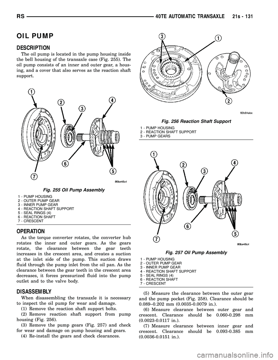
The oil pump is located in the pump housing inside
the bell housing of the transaxle case (Fig. 255). The
oil pump consists of an inner and outer gear, a hous-
ing, and a cover that also serves as the reaction shaft
support.
OPERATION
As the torque converter rotates, the converter hub
rotates the inner and outer gears. As the gears
rotate, the clearance between the gear teeth
increases in the crescent area, and creates a suction
at the inlet side of the pump. This suction draws
fluid through the pump inlet from the oil pan. As the
clearance between the gear teeth in the crescent area
decreases, it forces pressurized fluid into the pump
outlet and to the valve body.
DISASSEMBLY
When disassembling the transaxle it is necessary
to inspect the oil pump for wear and damage. (1) Remove the reaction shaft support bolts.
(2) Remove reaction shaft support from pump
housing (Fig. 256). (3) Remove the pump gears (Fig. 257) and check
for wear and damage on pump housing and gears. (4) Re-install the gears and check clearances. (5) Measure the clearance between the outer gear
and the pump pocket (Fig. 258). Clearance should be
0.089±0.202 mm (0.0035-0.0079 in.). (6) Measure clearance between outer gear and
crescent. Clearance should be 0.060-0.298 mm
(0.0023-0.0117 in.). (7) Measure clearance between inner gear and
crescent. Clearance should be 0.093-0.385 mm
(0.0036-0.0151 in.).
Fig. 255 Oil Pump Assembly
1 - PUMP HOUSING
2 - OUTER PUMP GEAR
3 - INNER PUMP GEAR
4 - REACTION SHAFT SUPPORT
5 - SEAL RINGS (4)
6 - REACTION SHAFT
7 - CRESCENT
Fig. 256 Reaction Shaft Support
1 - PUMP HOUSING
2 - REACTION SHAFT SUPPORT
3 - PUMP GEARS
Fig. 257 Oil Pump Assembly
1 - PUMP HOUSING
2 - OUTER PUMP GEAR
3 - INNER PUMP GEAR
4 - REACTION SHAFT SUPPORT
5 - SEAL RINGS (4)
6 - REACTION SHAFT
7 - CRESCENT
RS 40TE AUTOMATIC TRANSAXLE21s - 131
Page 1993 of 2585
(8) Position an appropriate piece of Plastigage
across both pump gears. (9) Align the Plastigage to a flat area on the reac-
tion shaft support housing. (10) Install the reaction shaft to the pump hous-
ing. Tighten the bolts to 27 N´m (20 ft. lbs.). (11) Remove bolts and carefully separate the hous-
ings. Measure the Plastigage following the instruc-
tions supplied. (12) Clearance between outer gear side and the
reaction shaft support should be 0.020-0.046 mm
(0.0008-0.0018 in.). Clearance between inner gear
side and the reaction shaft support should be 0.020-
0.046 mm (0.0008-0.0018 in.).
ASSEMBLY
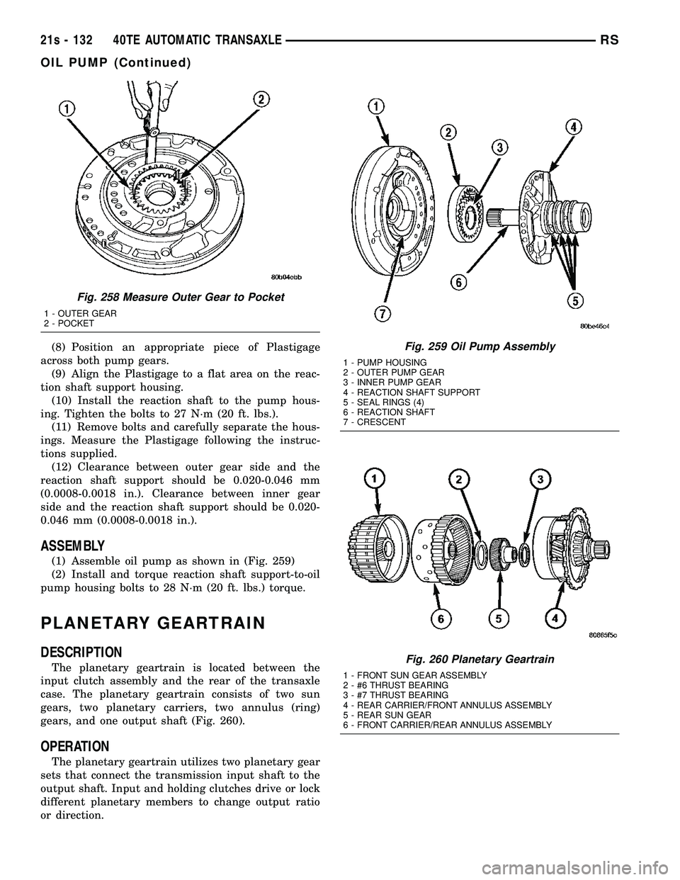
(1) Assemble oil pump as shown in (Fig. 259)
(2) Install and torque reaction shaft support-to-oil
pump housing bolts to 28 N´m (20 ft. lbs.) torque.
PLANETARY GEARTRAIN
DESCRIPTION
The planetary geartrain is located between the
input clutch assembly and the rear of the transaxle
case. The planetary geartrain consists of two sun
gears, two planetary carriers, two annulus (ring)
gears, and one output shaft (Fig. 260).
OPERATION
The planetary geartrain utilizes two planetary gear
sets that connect the transmission input shaft to the
output shaft. Input and holding clutches drive or lock
different planetary members to change output ratio
or direction.
Fig. 258 Measure Outer Gear to Pocket
1 - OUTER GEAR
2 - POCKET
Fig. 259 Oil Pump Assembly
1 - PUMP HOUSING
2 - OUTER PUMP GEAR
3 - INNER PUMP GEAR
4 - REACTION SHAFT SUPPORT
5 - SEAL RINGS (4)
6 - REACTION SHAFT
7 - CRESCENT
Fig. 260 Planetary Geartrain
1 - FRONT SUN GEAR ASSEMBLY
2 - #6 THRUST BEARING
3 - #7 THRUST BEARING
4 - REAR CARRIER/FRONT ANNULUS ASSEMBLY
5 - REAR SUN GEAR
6 - FRONT CARRIER/REAR ANNULUS ASSEMBLY
21s - 132 40TE AUTOMATIC TRANSAXLERS
OIL PUMP (Continued)
Page 2000 of 2585
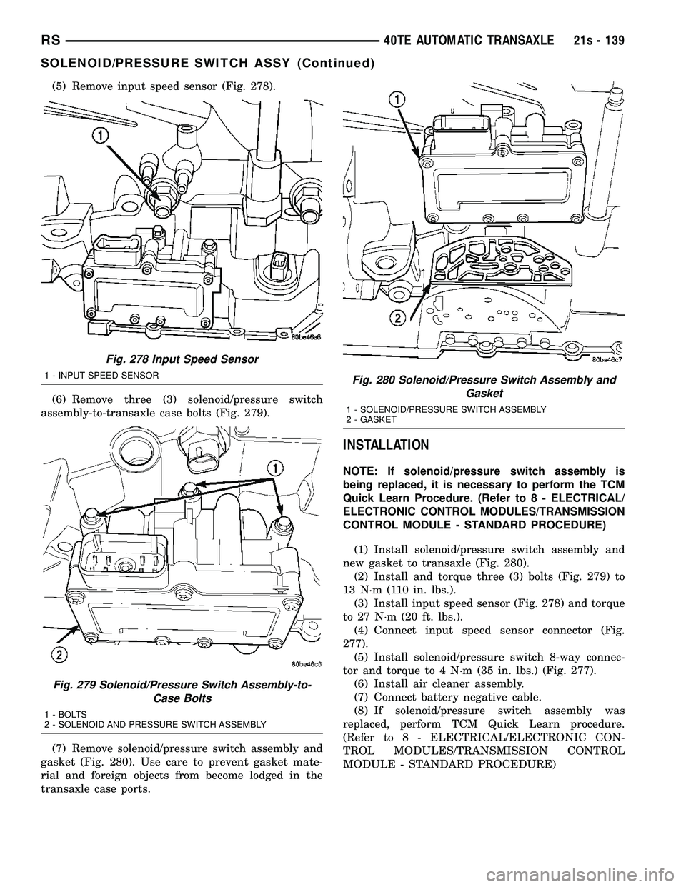
(5) Remove input speed sensor (Fig. 278).
(6) Remove three (3) solenoid/pressure switch
assembly-to-transaxle case bolts (Fig. 279).
(7) Remove solenoid/pressure switch assembly and
gasket (Fig. 280). Use care to prevent gasket mate-
rial and foreign objects from become lodged in the
transaxle case ports.
INSTALLATION
NOTE: If solenoid/pressure switch assembly is
being replaced, it is necessary to perform the TCM
Quick Learn Procedure. (Refer t o 8 - ELECTRICAL/
ELECTRONIC CONTROL MODULES/TRANSMISSION
CONTROL MODULE - STANDARD PROCEDURE)
(1) Install solenoid/pressure switch assembly and
new gasket to transaxle (Fig. 280). (2) Install and torque three (3) bolts (Fig. 279) to
13 N´m (110 in. lbs.). (3) Install input speed sensor (Fig. 278) and torque
to 27 N´m (20 ft. lbs.). (4) Connect input speed sensor connector (Fig.
277). (5) Install solenoid/pressure switch 8-way connec-
tor and torque to 4 N´m (35 in. lbs.) (Fig. 277). (6) Install air cleaner assembly.
(7) Connect battery negative cable.
(8) If solenoid/pressure switch assembly was
replaced, perform TCM Quick Learn procedure.
(Refer t o 8 - ELECTRICAL/ELECTRONIC CON-
TROL MODULES/TRANSMISSION CONTROL
MODULE - STANDARD PROCEDURE)
Fig. 278 Input Speed Sensor
1 - INPUT SPEED SENSOR
Fig. 279 Solenoid/Pressure Switch Assembly-to- Case Bolts
1 - BOLTS
2 - SOLENOID AND PRESSURE SWITCH ASSEMBLY
Fig. 280 Solenoid/Pressure Switch Assembly and Gasket
1 - SOLENOID/PRESSURE SWITCH ASSEMBLY
2 - GASKET
RS 40TE AUTOMATIC TRANSAXLE21s - 139
SOLENOID/PRESSURE SWITCH ASSY (Continued)
Page 2001 of 2585
SPEED SENSOR - INPUT
DESCRIPTION
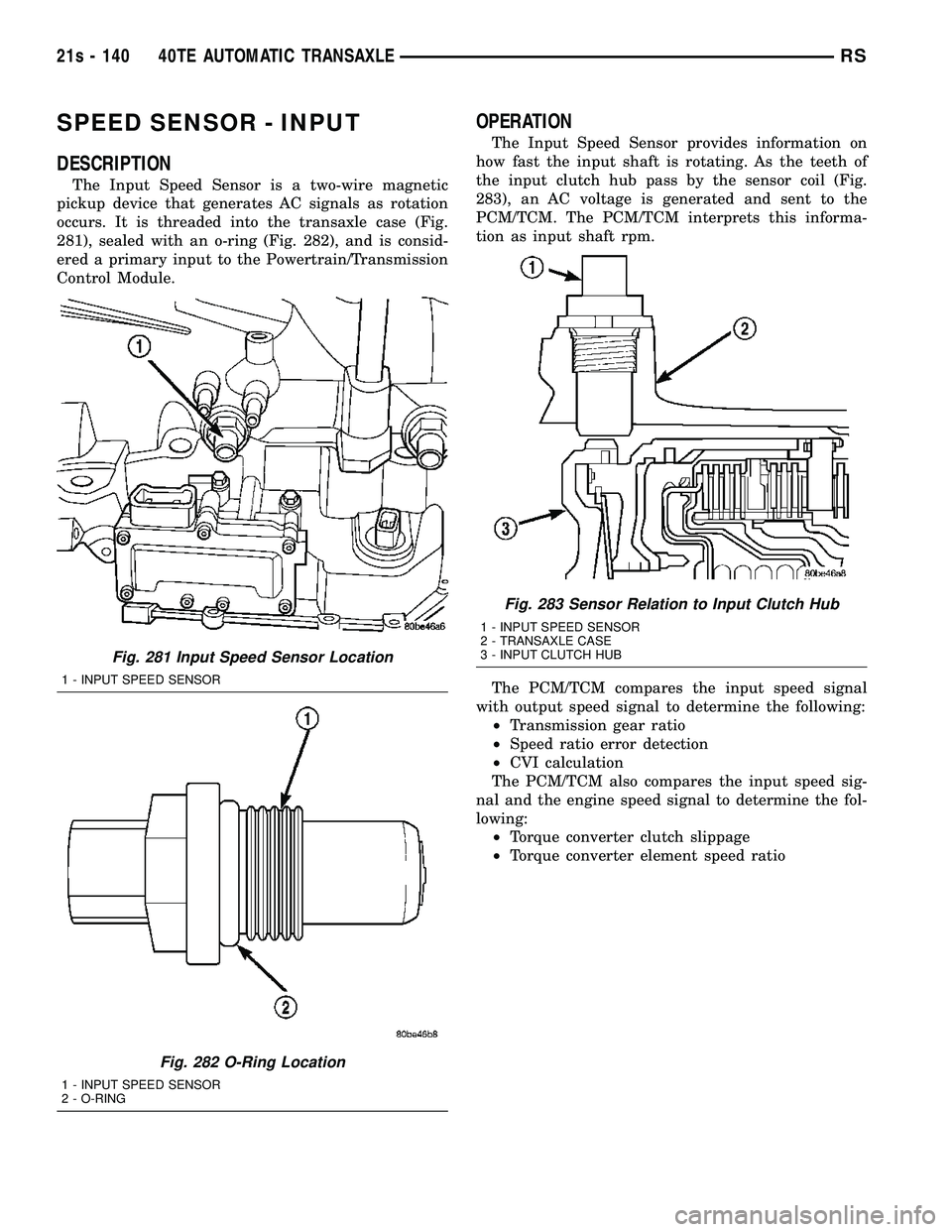
The Input Speed Sensor is a two-wire magnetic
pickup device that generates AC signals as rotation
occurs. It is threaded into the transaxle case (Fig.
281), sealed with an o-ring (Fig. 282), and is consid-
ered a primary input to the Powertrain/Transmission
Control Module.
OPERATION
The Input Speed Sensor provides information on
how fast the input shaft is rotating. As the teeth of
the input clutch hub pass by the sensor coil (Fig.
283), an AC voltage is generated and sent to the
PCM/TCM. The PCM/TCM interprets this informa-
tion as input shaft rpm.
The PCM/TCM compares the input speed signal
with output speed signal to determine the following: ² Transmission gear ratio
² Speed ratio error detection
² CVI calculation
The PCM/TCM also compares the input speed sig-
nal and the engine speed signal to determine the fol-
lowing: ² Torque converter clutch slippage
² Torque converter element speed ratio
Fig. 281 Input Speed Sensor Location
1 - INPUT SPEED SENSOR
Fig. 282 O-Ring Location
1 - INPUT SPEED SENSOR
2 - O-RING
Fig. 283 Sensor Relation to Input Clutch Hub
1 - INPUT SPEED SENSOR
2 - TRANSAXLE CASE
3 - INPUT CLUTCH HUB
21s - 140 40TE AUTOMATIC TRANSAXLERS
Page 2005 of 2585

TORQUE CONVERTER
DESCRIPTION
The torque converter (Fig. 293) is a hydraulic
device that couples the engine crankshaft to the
transmission. The torque converter consists of an
outer shell with an internal turbine, a stator, an
overrunning clutch, an impeller and an electronically
applied converter clutch. The converter clutch pro-
vides reduced engine speed and greater fuel economy
when engaged. Clutch engagement also provides
reduced transmission fluid temperatures. The con-
verter clutch engages in third gear. The torque con-
verter hub drives the transmission oil (fluid) pump. The torque converter is a sealed, welded unit that
is not repairable and is serviced as an assembly.
Fig. 293 Torque Converter Assembly
1 - TURBINE
2 - IMPELLER
3 - HUB
4-STATOR
5 - CONVERTER CLUTCH DISC
6 - DRIVE PLATE
21s - 144 40TE AUTOMATIC TRANSAXLERS
Page 2006 of 2585

IMPELLER
The impeller (Fig. 294) is an integral part of the
converter housing. The impeller consists of curved
blades placed radially along the inside of the housing
on the transmission side of the converter. As the con-
verter housing is rotated by the engine, so is the
impeller, because they are one and the same and are
the driving member of the system.
Fig. 294 Impeller
1 - ENGINE FLEXPLATE 4 - ENGINE ROTATION
2 - OIL FLOW FROM IMPELLER SECTION INTO TURBINE
SECTION 5 - ENGINE ROTATION
3 - IMPELLER VANES AND COVER ARE INTEGRAL
RS 40TE AUTOMATIC TRANSAXLE21s - 145
TORQUE CONVERTER (Continued)
Page 2007 of 2585
TURBINE
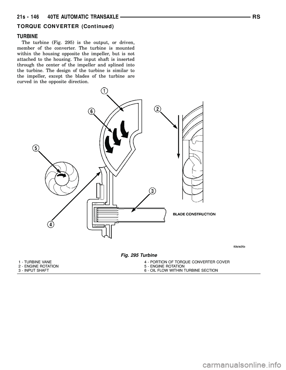
The turbine (Fig. 295) is the output, or driven,
member of the converter. The turbine is mounted
within the housing opposite the impeller, but is not
attached to the housing. The input shaft is inserted
through the center of the impeller and splined into
the turbine. The design of the turbine is similar to
the impeller, except the blades of the turbine are
curved in the opposite direction.
Fig. 295 Turbine
1 - TURBINE VANE
2 - ENGINE ROTATION
3 - INPUT SHAFT 4 - PORTION OF TORQUE CONVERTER COVER
5 - ENGINE ROTATION
6 - OIL FLOW WITHIN TURBINE SECTION
21s - 146 40TE AUTOMATIC TRANSAXLERS
TORQUE CONVERTER (Continued)
Page 2008 of 2585

STATOR
The stator assembly (Fig. 296) is mounted on a sta-
tionary shaft which is an integral part of the oil
pump. The stator is located between the impeller and
turbine within the torque converter case (Fig. 297).
The stator contains an over-running clutch, which
allows the stator to rotate only in a clockwise direc-
tion. When the stator is locked against the over-run-
ning clutch, the torque multiplication feature of the
torque converter is operational.
TORQUE CONVERTER CLUTCH (TCC)
The TCC (Fig. 298) was installed to improve the
efficiency of the torque converter that is lost to the
slippage of the fluid coupling. Although the fluid cou-
pling provides smooth, shock±free power transfer, it
is natural for all fluid couplings to slip. If the impel-
ler and turbine were mechanically locked together, a
zero slippage condition could be obtained. A hydraulic
piston was added to the turbine, and a friction mate-
rial was added to the inside of the front cover to pro-
vide this mechanical lock-up.
Fig. 296 Stator Components
1 - CAM (OUTER RACE)
2 - ROLLER
3 - SPRING
4 - INNER RACE
Fig. 297 Stator Location
1-STATOR
2 - IMPELLER
3 - FLUID FLOW
4 - TURBINE
Fig. 298 Torque Converter Clutch (TCC)
1 - IMPELLER FRONT COVER
2 - THRUST WASHER ASSEMBLY
3 - IMPELLER
4-STATOR
5 - TURBINE
6 - PISTON
7 - FRICTION DISC
RS 40TE AUTOMATIC TRANSAXLE21s - 147
TORQUE CONVERTER (Continued)