LUG NUT CHRYSLER VOYAGER 2005 User Guide
[x] Cancel search | Manufacturer: CHRYSLER, Model Year: 2005, Model line: VOYAGER, Model: CHRYSLER VOYAGER 2005Pages: 2339, PDF Size: 59.69 MB
Page 120 of 2339

Follow pressure bleeder manufacturer's instruc-
tions for use of pressure bleeding equipment.
(1) Install the Adapter Master Cylinder Pressure
Bleed Cap, Special Tool 6921 on the fluid reservoir of
the master cylinder (Fig. 2). Attach the fluid hose
from the pressure bleeder to the fitting on Special
Tool 6921.
(2) Attach a clear plastic hose to the bleeder screw
at one wheel and feed the hose into a clear jar con-
taining fresh brake fluid.
(3) Open the left rear wheel bleeder screw at least
one full turnor more to obtain an adequate flow of
brake fluid.
CAUTION: ªJust crackingº the bleeder screw often
restricts fluid flow, allowing only a slow, weak fluid
discharge of fluid. This practice will NOT get all the
air out. Make sure the bleeder is opened at least 1
full turn when bleeding.
(4) After 4 to 8 ounces of brake fluid has been bled
through the hydraulic system, and an air-free flow is
maintained in the hose and jar, this will indicate a
good bleed of the hydraulic system has been
obtained.
(5) Repeat the procedure at all the other remain-
ing bleeder screws.
(6) Check pedal travel. If pedal travel is excessive
or has not been improved, enough fluid has not
passed through the system to expel all the trapped
air. Be sure to monitor the fluid level in the pressure
bleeder, so it stays at a proper level so air will not
enter the brake system through the master cylinder.
(7) Perform a final adjustment of the rear brake
shoes (when applicable), then test drive vehicle to be
sure brakes are operating correctly and that pedal is
solid.SPECIFICATIONS
BRAKE FASTENER TORQUE
DESCRIPTION N´mFt.
Lbs.In.
Lbs.
ABS ICU Mounting Bolts To
Bracket11 Ð 9 7
ABS ICU Mounting
Bracket-To-Cradle Bolts28 21 250
ABS CAB-To-HCU Mounting
Screws2Ð17
ABS Wheel Speed Sensor
Head Mounting Bolt - Front13 Ð 115
ABS Wheel Speed Sensor
Head Mounting Bolt - Rear10 Ð 90
Adjustable Pedal Position
Sensor Mounting Screws7.5 66 Ð
Adjustable Pedal Module
Mounting Screws2.0 15 Ð
Brake Tube Nuts 17 Ð 145
Brake Hose Intermediate
Bracket Bolt12 Ð 105
Brake Hose-To-Caliper
Mounting Bolt47 35 Ð
Disc Brake Caliper Guide
Pin Bolts35 26 Ð
Disc Brake Caliper Bleeder
Screw15 Ð 125
Drum Brake Wheel Cylinder
Mounting Bolts8Ð75
Drum Brake Wheel Cylinder
Mounting Bleeder screw10 Ð 80
Drum Brake Support Plate
Mounting Bolts130 95 Ð
Junction Block (Non-ABS
Brakes) Mounting Bolts28 21 250
Master Cylinder Mounting
Nuts25 19 225
Power Brake Booster
Mounting Nuts28 21 250
Proportioning Valve
Mounting Bolts54 40 Ð
Proportioning Valve Axle
Bracket Mounting Bolt20 Ð 175
Parking Brake Lever (Pedal)
Mounting Bolts And Nut28 21 250
Wheel Mounting (Lug) Nuts 135 100 Ð
Fig. 2 Tool 6921 Installed On Master Cylinder
1 - SPECIAL TOOL 6921
2 - FLUID RESERVOIR
RSBRAKES - BASE5-9
BRAKES - BASE (Continued)
Page 134 of 2339

(3) Install the park brake actuator strut (Fig. 30)
on the leading brake shoe. Then install the park
brake actuator lever on the strut (Fig. 30).
(4) Install the automatic adjuster screw on the
leading brake shoe. Then install the trailing brake
shoe on the park brake actuating lever and park
brake actuating strut (Fig. 26). Position trailing
brake shoe on brake support plate.
(5) Install the brake shoe hold down pin and
spring on the trailing brake shoe (Fig. 25).
(6) Install the brake shoe to brake shoe upper
return spring (Fig. 24).
CAUTION: When installing the tension clip on the
automatic adjuster, it must be located on only the
threaded area of the adjuster assembly (Fig. 23). If it
is located on a non-threaded area of the adjuster, the
function of the automatic adjuster will be affected.
(7)Install the tension clip (Fig. 23) attaching the
upper return spring to the automatic adjuster assembly.
(8)Install the brake shoe to brake shoe lower return
springs on the brake shoes (Fig. 21) and (Fig. 22).
(9) Install automatic adjustment lever on the lead-
ing brake shoe of the rear brake assembly (Fig. 20).
(10) Install the actuating spring on the automatic
adjustment lever and leading brake shoe assembly
(Fig. 19).
(11) Verify that the automatic adjuster lever has
positive contact with the star wheel on the automatic
adjuster assembly.
(12) When all components of both rear brake
assemblies are correctly and fully installed, remove
the locking pliers from the front park brake cable.(13) Adjust brake shoes assemblies so as not to
interfere with brake drum installation.
(14) Install the rear brake drums on the hubs.
(15) Adjust rear brake shoes.
(16) Install the wheel and tire assembly.
(17) Tighten the wheel mounting stud nuts in
proper sequence until all nuts are torqued to half
specification. Then repeat the tightening sequence to
the full specified torque of 135 N´m (100 ft. lbs.).
(18) Lower the vehicle.
(19) Push the parking brake lever (pedal) to the
floor once and release pedal. This will automatically
remove the slack from and correctly adjust the park-
ing brake cables.
(20) Road test vehicle. The automatic adjuster will
continue the brake adjustment during the road test
of the vehicle.
ADJUSTMENTS
ADJUSTMENT - REAR DRUM BRAKE SHOES
NOTE: Normally, self-adjusting drum brakes do not
require manual brake shoe adjustment. Although, in
the event of a brake shoe replacement, it is advis-
able to make the initial adjustment manually to
speed up the adjusting time.
NOTE: Before raising the vehicle, verify the parking
brake lever is fully released.
(1) Raise the vehicle. (Refer to LUBRICATION &
MAINTENANCE/HOISTING - STANDARD PROCE-
DURE).
(2) Remove rubber plug from rear brake adjusting
hole in the rear brake support plate.
(3) Insert a thin screwdriver through the adjusting
hole in the support plate and against the star wheel
of the adjusting screw. Move handle of the tool down-
ward, rotating the star wheel until a slight drag is
felt when tire and wheel assembly is rotated.
(4) Insert a second thin screwdriver or piece of
welding rod into brake adjusting hole and push the
adjusting lever out of engagement with the star
wheel.Care should be taken so as not to bend
adjusting lever or distort lever spring.
(5) While holding the adjusting lever out of
engagement, back off the star wheel just enough to
ensure a free wheel with no brake shoe drag.
(6) Repeat the above adjustment at the other rear
wheel.
(7) Install the adjusting hole rubber plugs back in
the rear brake support plates.
(8) Lower the vehicle.
Fig. 30 Park Brake Components Assembled On
Leading Brake Shoe
1 - PARK BRAKE CABLE
2 - LEADING BRAKE SHOE
3 - PARK BRAKE ACTUATING STRUT
4 - PARK BRAKE ACTUATING LEVER
5 - BRAKE SUPPORT PLATE
RSBRAKES - BASE5-23
BRAKE PADS/SHOES - REAR DRUM (Continued)
Page 143 of 2339
(4) Remove the disc brake caliper from the disc
brake caliper adapter and hang it out of the way
using wire or a bungee cord. Use care not to overex-
tend the brake hose when doing this.
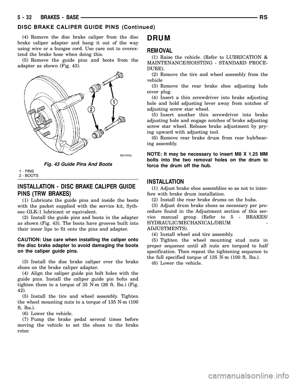
(5) Remove the guide pins and boots from the
adapter as shown (Fig. 43).
INSTALLATION - DISC BRAKE CALIPER GUIDE
PINS (TRW BRAKES)
(1) Lubricate the guide pins and inside the boots
with the packet supplied with the service kit, Syth-
eso GLK-1 lubricant or equivalent.
(2) Install the guide pins and boots in the adapter
as shown (Fig. 43). The boots have grooves built into
their inner lips to fit onto the pins and adapter.
CAUTION: Use care when installing the caliper onto
the disc brake adapter to avoid damaging the boots
on the caliper guide pins.
(3) Install the disc brake caliper over the brake
shoes on the brake caliper adapter.
(4) Align the caliper guide pin bolt holes with the
guide pins. Install the caliper guide pin bolts and
tighten them to a torque of 35 N´m (26 ft. lbs.) (Fig.
42).
(5) Install the tire and wheel assembly. Tighten
the wheel mounting nuts to a torque of 135 N´m (100
ft. lbs.).
(6) Lower the vehicle.
(7) Pump the brake pedal several times before
moving the vehicle to set the shoes to the brake
rotor.
DRUM
REMOVAL
(1) Raise the vehicle. (Refer to LUBRICATION &
MAINTENANCE/HOISTING - STANDARD PROCE-
DURE).
(2) Remove the tire and wheel assembly from the
vehicle
(3) Remove the rear brake shoe adjusting hole
cover plug.
(4) Insert a thin screwdriver into brake adjusting
hole and hold adjusting lever away from notches of
adjusting screw star wheel.
(5) Insert another thin screwdriver into brake
adjusting hole and engage notches of brake adjusting
screw star wheel. Release brake adjustment by pry-
ing upward with adjusting tool.
(6) Remove rear brake drum from rear hub/bear-
ing assembly.
NOTE: It may be necessary to insert M8 X 1.25 MM
bolts into the two removal holes on the drum to
force the drum off the hub.
INSTALLATION
(1) Adjust brake shoe assemblies so as not to inter-
fere with brake drum installation.
(2) Install the rear brake drums on the hubs.
(3) Adjust drum brake shoes as necessary per pro-
cedure found in the Adjustment section of this ser-
vice manual group (Refer to 5 - BRAKES/
HYDRAULIC/MECHANICAL/DRUM -
ADJUSTMENTS).
(4) Install wheel and tire assembly.
(5) Tighten the wheel mounting stud nuts in
proper sequence until all nuts are torqued to half
specification. Then repeat the tightening sequence to
the full specified torque of 135 N´m (100 ft. lbs.).
(6) Lower the vehicle.
Fig. 43 Guide Pins And Boots
1 - PINS
2 - BOOTS
5 - 32 BRAKES - BASERS
DISC BRAKE CALIPER GUIDE PINS (Continued)
Page 148 of 2339
(5) Remove nut and clamp securing battery to tray,
remove battery.
(6) Thoroughly clean all surfaces of the brake fluid
reservoir and master cylinder. Use only solvent such
as MopartBrake Parts Cleaner or equivalent.
(7) Remove wiring harness connector from brake
fluid level switch in master cylinder brake fluid res-
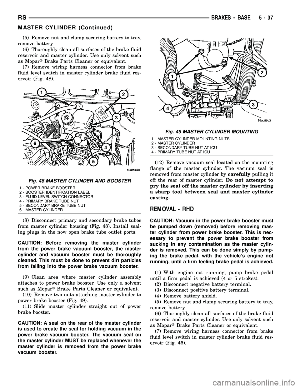
ervoir (Fig. 48).
(8) Disconnect primary and secondary brake tubes
from master cylinder housing (Fig. 48). Install seal-
ing plugs in the now open brake tube outlet ports.
CAUTION: Before removing the master cylinder
from the power brake vacuum booster, the master
cylinder and vacuum booster must be thoroughly
cleaned. This must be done to prevent dirt particles
from falling into the power brake vacuum booster.
(9) Clean area where master cylinder assembly
attaches to power brake booster. Use only a solvent
such as MopartBrake Parts Cleaner or equivalent.
(10) Remove two nuts attaching master cylinder to
power brake booster (Fig. 49).
(11) Slide master cylinder straight out of power
brake booster.
CAUTION: A seal on the rear of the master cylinder
is used to create the seal for holding vacuum in the
power brake vacuum booster. The vacuum seal on
the master cylinder MUST be replaced whenever the
master cylinder is removed from the power brake
vacuum booster.(12) Remove vacuum seal located on the mounting
flange of the master cylinder. The vacuum seal is
removed from master cylinder bycarefullypulling it
off the rear of master cylinder.Do not attempt to
pry the seal off the master cylinder by inserting
a sharp tool between seal and master cylinder
casting.
REMOVAL - RHD
CAUTION: Vacuum in the power brake booster must
be pumped down (removed) before removing mas-
ter cylinder from power brake booster. This is nec-
essary to prevent the power brake booster from
sucking in any contamination as the master cylin-
der is removed. This can be done simply by pump-
ing the brake pedal, with the vehicle's engine not
running, until a firm feeling brake pedal is achieved.
(1) With engine not running, pump brake pedal
until a firm pedal is achieved (4 or 5 strokes).
(2) Disconnect negative battery terminal.
(3) Disconnect positive battery terminal.
(4) Remove battery shield.
(5) Remove nut and clamp securing battery to tray,
remove battery.
(6) Thoroughly clean all surfaces of the brake fluid
reservoir and master cylinder. Use only solvent such
as MopartBrake Parts Cleaner or equivalent.
(7) Remove wiring harness connector from brake
fluid level switch in master cylinder brake fluid res-
ervoir (Fig. 46).
Fig. 48 MASTER CYLINDER AND BOOSTER
1 - POWER BRAKE BOOSTER
2 - BOOSTER IDENTIFICATION LABEL
3 - FLUID LEVEL SWITCH CONNECTOR
4 - PRIMARY BRAKE TUBE NUT
5 - SECONDARY BRAKE TUBE NUT
6 - MASTER CYLINDER
Fig. 49 MASTER CYLINDER MOUNTING
1 - MASTER CYLINDER MOUNTING NUTS
2 - MASTER CYLINDER
3 - SECONDARY TUBE NUT AT ICU
4 - PRIMARY TUBE NUT AT ICU
RSBRAKES - BASE5-37
MASTER CYLINDER (Continued)
Page 149 of 2339

(8) Disconnect primary and secondary brake tubes
from master cylinder housing (Fig. 50). Install seal-
ing plugs in the now open brake tube outlet ports.
CAUTION: Before removing the master cylinder
from the power brake vacuum booster, the master
cylinder and vacuum booster must be thoroughly
cleaned. This must be done to prevent dirt particles
from falling into the power brake vacuum booster.
(9) Clean area where master cylinder assembly
attaches to power brake booster. Use only a solvent
such as MopartBrake Parts Cleaner or equivalent.
(10) Remove two nuts attaching master cylinder to
power brake booster (Fig. 50).
(11) Slide master cylinder straight out of power
brake booster.
CAUTION: A seal on the rear of the master cylinder
is used to create the seal for holding vacuum in the
power brake vacuum booster. The vacuum seal on
the master cylinder MUST be replaced whenever the
master cylinder is removed from the power brake
vacuum booster.
(12) Remove vacuum seal located on the mounting
flange of the master cylinder. The vacuum seal is
removed from master cylinder bycarefullypulling it
off the rear of master cylinder.Do not attempt to
pry the seal off the master cylinder by inserting
a sharp tool between seal and master cylinder
casting.DISASSEMBLY - MASTER CYLINDER (FLUID
RESERVOIR)
(1) Clean master cylinder housing and brake fluid
reservoir. Use only a solvent such as Mopar Brake
Parts Cleaner or an equivalent.
(2) Remove brake fluid reservoir cap. Using a
syringe or equivalent type tool empty as much brake
fluid as possible from the reservoir.
CAUTION: When removing fluid reservoir from the
master cylinder, do not pry off using any type of
tool. This can damage the fluid reservoir or master
cylinder housing.
(3) Remove the master cylinder assembly from the
power brake vacuum booster. (Refer to 5 - BRAKES -
BASE/HYDRAULIC/MECHANICAL/MASTER CYL-
INDER - REMOVAL).
(4) Mount the master cylinder in a vise using the
master cylinder mounting flange.
(5) Using correct size pin punch, remove the two
retaining pins between the fluid reservoir and master
cylinder housing (Fig. 51).
(6) Rock the brake fluid reservoir from side to side
while pulling up to remove it from the seal grommets
in master cylinder housing.
(7) Remove the two master cylinder housing to
brake fluid reservoir seal grommets (Fig. 52).
Fig. 50 RHD MASTER CYLINDER MOUNTING
1 - PRIMARY BRAKE TUBE NUT
2 - SECONDARY BRAKE TUBE NUT
3 - MASTER CYLINDER MOUNTING NUTS
Fig. 51 Fluid Reservoir Retaining Pins (Typical)
1 - FLUID RESERVOIR
2 - RETAINING PINS
3 - MASTER CYLINDER
5 - 38 BRAKES - BASERS
MASTER CYLINDER (Continued)
Page 158 of 2339

(6) Remove screw securing engine coolant filler
tube to battery tray.
(7) If the vehicle is equipped with speed control,
disconnect the vacuum hose at the vacuum tank built
into the battery tray.
(8) Remove the two nuts and one bolt securing bat-
tery tray in place. Remove battery tray.
(9) If vehicle is equipped with speed control:
(a) Disconnect wiring harness connector from
the speed control servo.
(b) Remove the two servo mounting nuts.
(c) Lay speed control servo off to the side, out of
the way.
(10) Remove the wiper module (unit). (Refer to 8 -
ELECTRICAL/WIPERS/WASHERS/WIPER MOD-
ULE - REMOVAL)
(11) Disconnect wiring harness connector from
brake fluid level switch in master cylinder fluid res-
ervoir (Fig. 66).
CAUTION: Before removing the master cylinder
from the power brake vacuum booster, the master
cylinder and vacuum booster must be thoroughly
cleaned. This must be done to prevent dirt particles
from falling into the power brake vacuum booster.
(12) Clean area where master cylinder assembly
attaches to power brake booster. Use only a solvent
such as MopartBrake Parts Cleaner or equivalent.(13) Disconnect primary and secondary brake
tubes from ABS integrated control unit or non-ABS
junction block (Fig. 67). Install sealing plugs in the
now open brake tube ports and install caps on ends
of tubes.
NOTE: It is not necessary to remove the brake
tubes from the master cylinder when removing the
master cylinder from the vacuum booster.
(14) Remove two nuts attaching master cylinder to
power brake booster (Fig. 67).
(15) Slide master cylinder straight out of power
brake booster. Remove master cylinder with primary
and secondary tubes from vehicle.
CAUTION: A seal on the rear of the master cylinder
is used to create the seal for holding vacuum in the
power brake vacuum booster. The vacuum seal on
the master cylinder MUST be replaced whenever the
master cylinder is removed from the power brake
vacuum booster.
(16) Disconnect vacuum hose from check valve
located on vacuum booster.DO NOT REMOVE
CHECK VALVE FROM POWER BRAKE
BOOSTER.
Fig. 66 Master Cylinder And Booster
1 - POWER BRAKE BOOSTER
2 - BOOSTER IDENTIFICATION LABEL
3 - FLUID LEVEL SWITCH CONNECTOR
4 - PRIMARY BRAKE TUBE NUT
5 - SECONDARY BRAKE TUBE NUT
6 - MASTER CYLINDER
Fig. 67 Master Cylinder Mounting
1 - MASTER CYLINDER MOUNTING NUTS
2 - MASTER CYLINDER
3 - SECONDARY TUBE NUT AT ICU
4 - PRIMARY TUBE NUT AT ICU
RSBRAKES - BASE5-47
POWER BRAKE BOOSTER (Continued)
Page 170 of 2339

Minimum allowable thickness is the minimum
thickness which the brake rotor machined surface
may be cut to.
CAUTION: Do not machine the rotor if it will cause
the rotor to fall below minimum thickness.
Before installation, verify the brake rotor face and
the hub adapters are free of any chips, rust, or con-
tamination.
When mounting and using the brake lathe, strict
attention to the brake lathe manufacturer's operating
instructions is required.
Machine both sides of the brake rotor at the same
time. Cutting both sides at the same time minimizes
the possibility of a tapered or uneven cut.
When refacing a rotor, the required TIR (Total
Indicator Reading) and thickness variation limits
MUST BE MAINTAINED. Extreme care in the oper-
ation of rotor turning equipment is required. Specifi-
cations for brake rotor machining can be found in
this section's specification table. (Refer to 5 -
BRAKES/HYDRAULIC/MECHANICAL/ROTOR -
SPECIFICATIONS)
REMOVAL - FRONT BRAKE ROTOR
(1) Raise vehicle on jackstands or centered on a
frame contact type hoist. See Hoisting in Lubrication
and Maintenance.
(2) Remove the front wheel and tire assembly.
(3) Remove the two mounting bolts securing the
disc brake caliper adapter with brake caliper to the
steering knuckle (Fig. 91).
(4) Remove the disc brake caliper and adapter as
an assembly from the steering knuckle (Fig. 91).
Hang the assembly out of the way using wire or a
bungee cord. Use care not to overextend the brake
hose when doing this.
(5) Remove any retainer clips from the wheel
mounting studs.
(6) Remove brake rotor from hub by pulling it
straight off wheel mounting studs (Fig. 91).
INSTALLATION - FRONT BRAKE ROTOR
(1) Install the brake rotor back on the hub and
bearing (Fig. 91).(2) Install brake caliper and adapter back over
brake rotor aligning adapter with mounting holes on
steering knuckle (Fig. 91).
(3) Install the two adapter mounting bolts securing
the adapter to the steering knuckle. Tighten the
mounting bolts to 169 N´m (125 ft. lbs.) torque.
(4) Install wheel and tire assembly on vehicle.
Tighten the wheel mounting lug nuts in proper
sequence until all nuts are torqued to half specifica-
tion, then repeat the tightening sequence to the full
specified torque of 135 N´m (100 ft. lbs.).
(5) Lower vehicle to the ground.
Fig. 91 Front Brake Mounting
1 - BRAKE ROTOR
2 - HUB AND BEARING
3 - STEERING KNUCKLE
4 - ADAPTER MOUNTING BOLTS
5 - BRAKE CALIPER
6 - ADAPTER
7 - CLIP
RSBRAKES - BASE5-59
ROTOR (Continued)
Page 173 of 2339
tightening sequence to the full specified torque of 135
N´m (100 ft. lbs.).
(12) Adjust drum brake shoes. (Refer to 5 -
BRAKES/HYDRAULIC/MECHANICAL/BRAKE
PADS/SHOES - ADJUSTMENTS)
(13) Remove brake pedal depressor tool.
(14) Bleed the brake system as necessary. (Refer to
5 - BRAKES - BASE - STANDARD PROCEDURE).
(15) Lower the vehicle.
WHEEL CYLINDERS
REMOVAL
(1) Using a brake pedal depressor, move and
secure brake pedal to a position past its first 1 inch
of travel. This will prevent brake fluid from draining
out of master cylinder when brake tube is remove
from wheel cylinder.
(2) Raise vehicle. (Refer to LUBRICATION &
MAINTENANCE/HOISTING - STANDARD PROCE-
DURE).
(3) Remove wheel and tire assembly.
(4) Disconnect brake tube from rear of wheel cylin-
der. Cap open ends
(5) Remove brake drum.
(6) Remove brake shoes from brake support plate
(Discard if contaminated).(Refer to 5 - BRAKES/HY-
DRAULIC/MECHANICAL/BRAKE PADS/SHOES -
REMOVAL)
(7) Remove the 2 bolts attaching the wheel cylin-
der to the brake support plate.
(8) Remove the wheel cylinder from the brake sup-
port plate.
INSPECTION
With brake drums removed, inspect the wheel cyl-
inder boots for evidence of a brake fluid leak. Visu-
ally check the boots for cuts, tears, or heat cracks. If
any of these conditions exist, the wheel cylinders
should be completely cleaned, inspected and new
parts installed.
If a wheel cylinder is leaking and the brake lining
material is saturated with brake fluid, the brake
shoes must be replaced.
INSTALLATION
(1) Apply sealant such as Mopar Gasket-In-A-Tube
or equivalent around the wheel cylinder opening in
the brake support plate.
(2) Install wheel cylinder onto brake support.
Install and tighten the wheel cylinder to brake sup-
port plate attaching bolts to 8 N´m (75 in. lbs.)
torque.
(3) Install brake tube into wheel cylinder. Tighten
tube nut to a torque of 17 N´m (145 in. lbs.) torque.(4) Install the rear brake shoes on the brake sup-
port plate. (Refer to 5 - BRAKES/HYDRAULIC/ME-
CHANICAL/BRAKE PADS/SHOES -
INSTALLATION).
(5) Install brake drum.
(6) Install wheel and tire. Install and tighten
wheel lug nuts to 135 N´m (100 ft. lbs.).
(7) Adjust drum brake shoes. (Refer to 5 -
BRAKES/HYDRAULIC/MECHANICAL/BRAKE
PADS/SHOES - ADJUSTMENTS)
(8) Remove brake pedal depressor tool.
(9) Bleed the brake system as necessary. (Refer to
5 - BRAKES - BASE - STANDARD PROCEDURE).
(10) Lower vehicle.
PARKING BRAKE
DESCRIPTION
DESCRIPTION
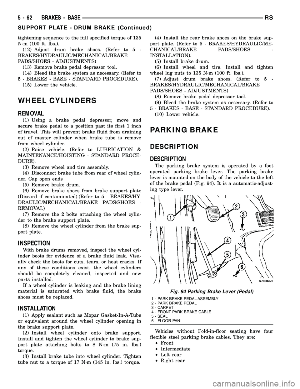
The parking brake system is operated by a foot
operated parking brake lever. The parking brake
lever is mounted on the body of the vehicle to the left
of the brake pedal (Fig. 94). It is a automatic-adjust-
ing type lever.
Vehicles without Fold-in-floor seating have four
flexible steel parking brake cables. They are:
²Front
²Intermediate
²Left rear
²Right rear
Fig. 94 Parking Brake Lever (Pedal)
1 - PARK BRAKE PEDAL ASSEMBLY
2 - PARK BRAKE PEDAL
3 - CARPET
4 - FRONT PARK BRAKE CABLE
5 - SEAL
6 - FLOOR PAN
5 - 62 BRAKES - BASERS
SUPPORT PLATE - DRUM BRAKE (Continued)
Page 217 of 2339
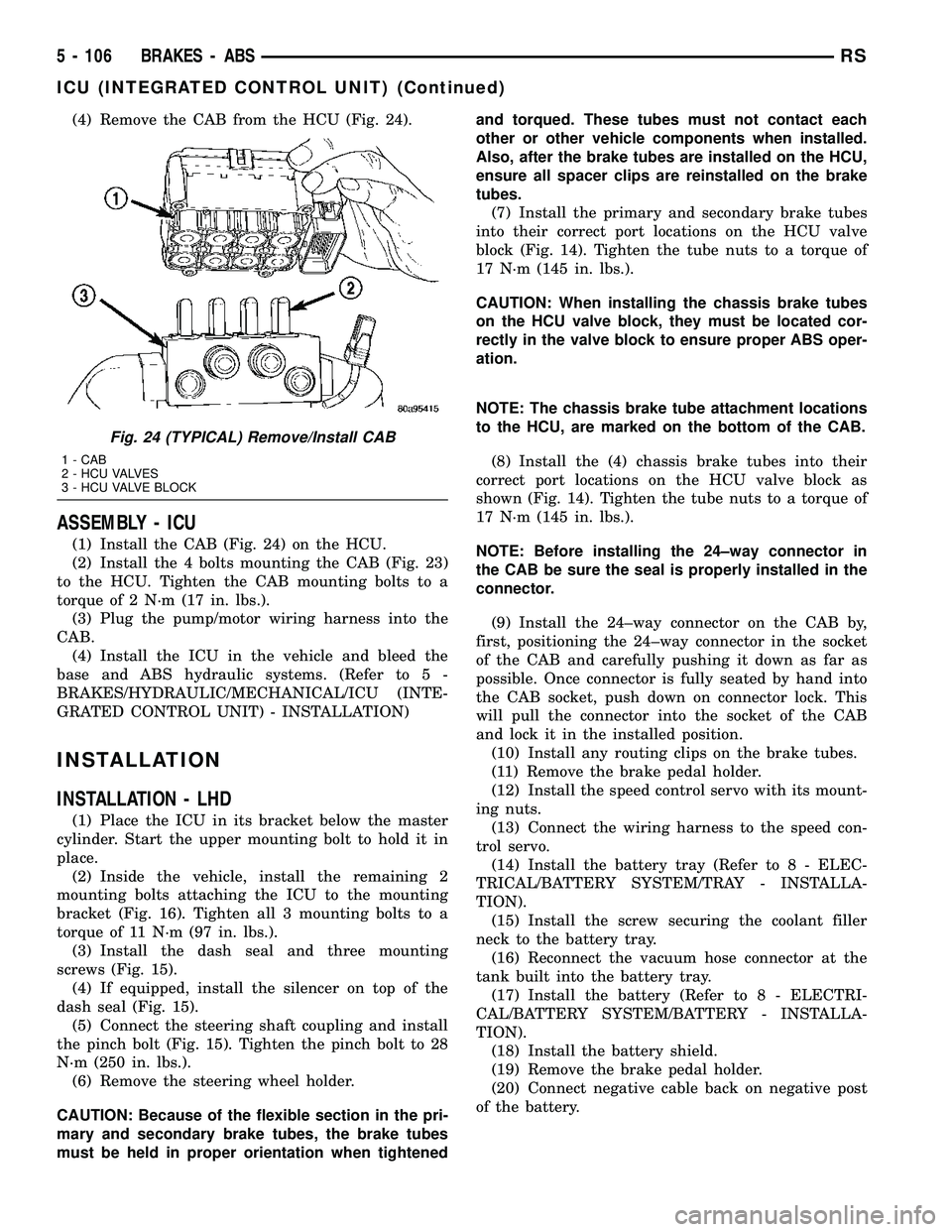
(4) Remove the CAB from the HCU (Fig. 24).
ASSEMBLY - ICU
(1) Install the CAB (Fig. 24) on the HCU.
(2) Install the 4 bolts mounting the CAB (Fig. 23)
to the HCU. Tighten the CAB mounting bolts to a
torque of 2 N´m (17 in. lbs.).
(3) Plug the pump/motor wiring harness into the
CAB.
(4) Install the ICU in the vehicle and bleed the
base and ABS hydraulic systems. (Refer to 5 -
BRAKES/HYDRAULIC/MECHANICAL/ICU (INTE-
GRATED CONTROL UNIT) - INSTALLATION)
INSTALLATION
INSTALLATION - LHD
(1) Place the ICU in its bracket below the master
cylinder. Start the upper mounting bolt to hold it in
place.
(2) Inside the vehicle, install the remaining 2
mounting bolts attaching the ICU to the mounting
bracket (Fig. 16). Tighten all 3 mounting bolts to a
torque of 11 N´m (97 in. lbs.).
(3) Install the dash seal and three mounting
screws (Fig. 15).
(4) If equipped, install the silencer on top of the
dash seal (Fig. 15).
(5) Connect the steering shaft coupling and install
the pinch bolt (Fig. 15). Tighten the pinch bolt to 28
N´m (250 in. lbs.).
(6) Remove the steering wheel holder.
CAUTION: Because of the flexible section in the pri-
mary and secondary brake tubes, the brake tubes
must be held in proper orientation when tightenedand torqued. These tubes must not contact each
other or other vehicle components when installed.
Also, after the brake tubes are installed on the HCU,
ensure all spacer clips are reinstalled on the brake
tubes.
(7) Install the primary and secondary brake tubes
into their correct port locations on the HCU valve
block (Fig. 14). Tighten the tube nuts to a torque of
17 N´m (145 in. lbs.).
CAUTION: When installing the chassis brake tubes
on the HCU valve block, they must be located cor-
rectly in the valve block to ensure proper ABS oper-
ation.
NOTE: The chassis brake tube attachment locations
to the HCU, are marked on the bottom of the CAB.
(8) Install the (4) chassis brake tubes into their
correct port locations on the HCU valve block as
shown (Fig. 14). Tighten the tube nuts to a torque of
17 N´m (145 in. lbs.).
NOTE: Before installing the 24±way connector in
the CAB be sure the seal is properly installed in the
connector.
(9) Install the 24±way connector on the CAB by,
first, positioning the 24±way connector in the socket
of the CAB and carefully pushing it down as far as
possible. Once connector is fully seated by hand into
the CAB socket, push down on connector lock. This
will pull the connector into the socket of the CAB
and lock it in the installed position.
(10) Install any routing clips on the brake tubes.
(11) Remove the brake pedal holder.
(12) Install the speed control servo with its mount-
ing nuts.
(13) Connect the wiring harness to the speed con-
trol servo.
(14) Install the battery tray (Refer to 8 - ELEC-
TRICAL/BATTERY SYSTEM/TRAY - INSTALLA-
TION).
(15) Install the screw securing the coolant filler
neck to the battery tray.
(16) Reconnect the vacuum hose connector at the
tank built into the battery tray.
(17) Install the battery (Refer to 8 - ELECTRI-
CAL/BATTERY SYSTEM/BATTERY - INSTALLA-
TION).
(18) Install the battery shield.
(19) Remove the brake pedal holder.
(20) Connect negative cable back on negative post
of the battery.
Fig. 24 (TYPICAL) Remove/Install CAB
1 - CAB
2 - HCU VALVES
3 - HCU VALVE BLOCK
5 - 106 BRAKES - ABSRS
ICU (INTEGRATED CONTROL UNIT) (Continued)
Page 228 of 2339
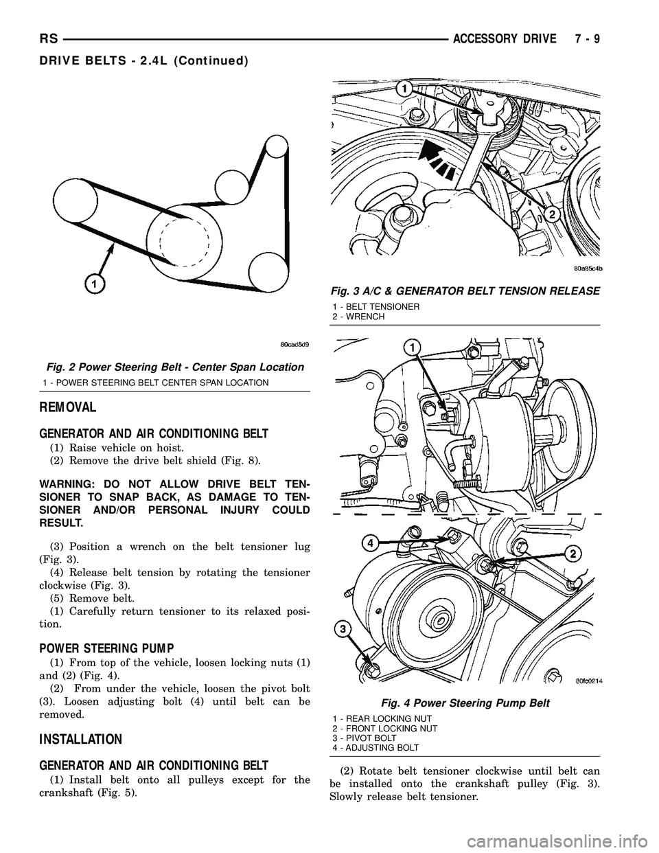
REMOVAL
GENERATOR AND AIR CONDITIONING BELT
(1) Raise vehicle on hoist.
(2) Remove the drive belt shield (Fig. 8).
WARNING: DO NOT ALLOW DRIVE BELT TEN-
SIONER TO SNAP BACK, AS DAMAGE TO TEN-
SIONER AND/OR PERSONAL INJURY COULD
RESULT.
(3) Position a wrench on the belt tensioner lug
(Fig. 3).
(4) Release belt tension by rotating the tensioner
clockwise (Fig. 3).
(5) Remove belt.
(1) Carefully return tensioner to its relaxed posi-
tion.
POWER STEERING PUMP
(1) From top of the vehicle, loosen locking nuts (1)
and (2) (Fig. 4).
(2) From under the vehicle, loosen the pivot bolt
(3). Loosen adjusting bolt (4) until belt can be
removed.
INSTALLATION
GENERATOR AND AIR CONDITIONING BELT
(1) Install belt onto all pulleys except for the
crankshaft (Fig. 5).(2) Rotate belt tensioner clockwise until belt can
be installed onto the crankshaft pulley (Fig. 3).
Slowly release belt tensioner.
Fig. 2 Power Steering Belt - Center Span Location
1 - POWER STEERING BELT CENTER SPAN LOCATION
Fig. 3 A/C & GENERATOR BELT TENSION RELEASE
1 - BELT TENSIONER
2 - WRENCH
Fig. 4 Power Steering Pump Belt
1 - REAR LOCKING NUT
2 - FRONT LOCKING NUT
3 - PIVOT BOLT
4 - ADJUSTING BOLT
RSACCESSORY DRIVE7-9
DRIVE BELTS - 2.4L (Continued)