LUG NUT CHRYSLER VOYAGER 2005 Owner's Manual
[x] Cancel search | Manufacturer: CHRYSLER, Model Year: 2005, Model line: VOYAGER, Model: CHRYSLER VOYAGER 2005Pages: 2339, PDF Size: 59.69 MB
Page 241 of 2339
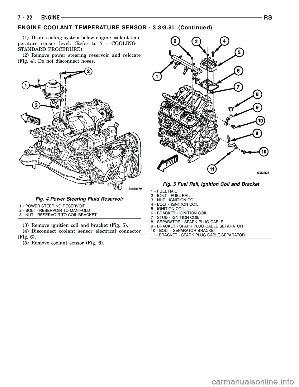
(1) Drain cooling system below engine coolant tem-
perature sensor level. (Refer to 7 - COOLING -
STANDARD PROCEDURE)
(2) Remove power steering reservoir and relocate
(Fig. 4). Do not disconnect hoses.
(3) Remove ignition coil and bracket (Fig. 5).
(4) Disconnect coolant sensor electrical connector
(Fig. 6).
(5) Remove coolant sensor (Fig. 6).
Fig. 4 Power Steering Fluid Reservoir
1 - POWER STEERING RESERVOIR
2 - BOLT - RESERVOIR TO MANIFOLD
3 - NUT - RESERVOIR TO COIL BRACKET
Fig. 5 Fuel Rail, Ignition Coil and Bracket
1 - FUEL RAIL
2 - BOLT - FUEL RAIL
3 - NUT - IGNITION COIL
4 - BOLT - IGNITION COIL
5 - IGNITION COIL
6 - BRACKET - IGNITION COIL
7 - STUD - IGNITION COIL
8 - SEPARATOR - SPARK PLUG CABLE
9 - BRACKET - SPARK PLUG CABLE SEPARATOR
10 - BOLT - SEPARATOR BRACKET
11 - BRACKET - SPARK PLUG CABLE SEPARATOR
7 - 22 ENGINERS
ENGINE COOLANT TEMPERATURE SENSOR - 3.3/3.8L (Continued)
Page 267 of 2339
DIAGNOSIS AND TESTING
ANTENNA BODY AND CABLE
WARNING: ON VEHICLES EQUIPPED WITH AIR-
BAGS, REFER TO ELECTRICAL, RESTRAINTS
BEFORE ATTEMPTING ANY STEERING WHEEL,
STEERING COLUMN, OR INSTRUMENT PANEL
COMPONENT DIAGNOSIS OR SERVICE. FAILURE
TO TAKE THE PROPER PRECAUTIONS COULD
RESULT IN ACCIDENTAL AIRBAG DEPLOYMENT
AND POSSIBLE PERSONAL INJURY.
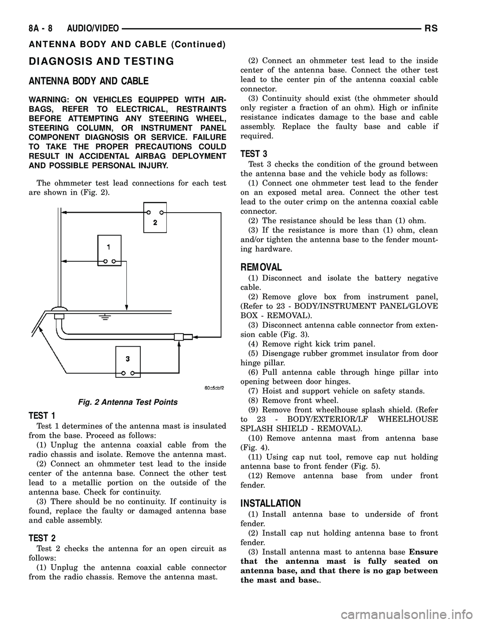
The ohmmeter test lead connections for each test
are shown in (Fig. 2).
TEST 1
Test 1 determines of the antenna mast is insulated
from the base. Proceed as follows:
(1) Unplug the antenna coaxial cable from the
radio chassis and isolate. Remove the antenna mast.
(2) Connect an ohmmeter test lead to the inside
center of the antenna base. Connect the other test
lead to a metallic portion on the outside of the
antenna base. Check for continuity.
(3) There should be no continuity. If continuity is
found, replace the faulty or damaged antenna base
and cable assembly.
TEST 2
Test 2 checks the antenna for an open circuit as
follows:
(1) Unplug the antenna coaxial cable connector
from the radio chassis. Remove the antenna mast.(2) Connect an ohmmeter test lead to the inside
center of the antenna base. Connect the other test
lead to the center pin of the antenna coaxial cable
connector.
(3) Continuity should exist (the ohmmeter should
only register a fraction of an ohm). High or infinite
resistance indicates damage to the base and cable
assembly. Replace the faulty base and cable if
required.
TEST 3
Test 3 checks the condition of the ground between
the antenna base and the vehicle body as follows:
(1) Connect one ohmmeter test lead to the fender
on an exposed metal area. Connect the other test
lead to the outer crimp on the antenna coaxial cable
connector.
(2) The resistance should be less than (1) ohm.
(3) If the resistance is more than (1) ohm, clean
and/or tighten the antenna base to the fender mount-
ing hardware.
REMOVAL
(1) Disconnect and isolate the battery negative
cable.
(2) Remove glove box from instrument panel,
(Refer to 23 - BODY/INSTRUMENT PANEL/GLOVE
BOX - REMOVAL).
(3) Disconnect antenna cable connector from exten-
sion cable (Fig. 3).
(4) Remove right kick trim panel.
(5) Disengage rubber grommet insulator from door
hinge pillar.
(6) Pull antenna cable through hinge pillar into
opening between door hinges.
(7) Hoist and support vehicle on safety stands.
(8) Remove front wheel.
(9) Remove front wheelhouse splash shield. (Refer
to 23 - BODY/EXTERIOR/LF WHEELHOUSE
SPLASH SHIELD - REMOVAL).
(10) Remove antenna mast from antenna base
(Fig. 4).
(11) Using cap nut tool, remove cap nut holding
antenna base to front fender (Fig. 5).
(12) Remove antenna base from under front
fender.
INSTALLATION
(1) Install antenna base to underside of front
fender.
(2) Install cap nut holding antenna base to front
fender.
(3) Install antenna mast to antenna baseEnsure
that the antenna mast is fully seated on
antenna base, and that there is no gap between
the mast and base..
Fig. 2 Antenna Test Points
8A - 8 AUDIO/VIDEORS
ANTENNA BODY AND CABLE (Continued)
Page 370 of 2339

REMOVAL
REMOVAL - 2.4L
The electronic ignition coil pack attaches directly
to the valve cover.
(1) Diconnect the negative battery cable.
(2) Disconnect electrical connector from coil pack.
(3) Remove coil pack mounting bolts.(4) Remove coil pack and heat shield (Fig. 9).
REMOVAL - 3.3/3.8L
(1) Disconnect the negative battery cable.
(2) Remove the throttle and speed control cables
from clip.
(3) Remove 2 bolts from the Power steering reser-
voir to intake manifold.
(4) Loosen the lower nut for the power steering
reservoir from stud on ignition coil bracket.
(5) Reposition the Power steering reservoir (Fig.
11).
(6) Remove the ignition cables from the ignition
coil.
(7) Disconnect the electrical connector from the
ignition coil.
(8) Remove 2 nuts from the ignition coil studs.
INSTALLATION
INSTALLATION - 2.4L
(1) Install ignition coil and heat shield to valve
cover and tighten bolts.
(2) Connect the electrical connector to the ignition
coil.
(3) Transfer spark plug cables to new coil pack.
The coil pack towers are numbered with the cylinder
identification. Be sure the ignition cables are fully
seated onto the towers.
(4) Connect the negative battery cable.
Fig. 9 IGNITION COIL - 2.4L
Fig. 10 IGNITION COIL - 3.3/3.8L
1 -Ignition Coil
Fig. 11 IGNITION COIL BRACKET 3.3/3.8L
RSIGNITION CONTROL8I-7
IGNITION COIL (Continued)
Page 451 of 2339
AUTOMATIC DAY / NIGHT
MIRROR
DESCRIPTION
An automatic dimming inside day/night rear view
mirror and an automatic dimming driver side outside
rear view mirror are available factory-installed
options on this model. Following is a general descrip-
tion of this optional equipment.
The automatic day/night mirror is able to automat-
ically change its reflectance. A thin layer of electro-
chromic material between two pieces of conductive
glass make up the face of the mirror. Two photocell
sensors are used to monitor light levels and adjust
the reflectance of the mirror to reduce the glare of
headlamps approaching the vehicle from the rear.
For removal procedures, (Refer to 23 - BODY/IN-
TERIOR/REAR VIEW MIRROR - REMOVAL).
OPERATION
The ambient photocell sensor faces forward, to
detect the outside light levels. A second sensor faces
rearward to detect the light level received through
the vehicles back window. When the difference
between the two light levels becomes too great (the
light level received at the rear of the mirror is much
higher than that at the front of the mirror), the mir-
ror begins to darken.
The mirror switch allows the driver a manual con-
trol of whether the automatic dimming feature is
operational. When AUTO is selected a small Light-
Emitting Diode (LED), to the right of the mirror
switch, is illuminated. The automatic dimming fea-
ture will only operate when the ignition switch is in
the On position. The mirror also senses the backup
lamp circuit, and will automatically disable its self-
dimming feature whenever the transmission gear
selector is in the Reverse position.
NOTE: The mirror always defaults to an ON state
upon ignition.
The driver side automatic dimming mirror is stan-
dard with the automatic dimming inside mirror. The
signal to control the dimming of that mirror is gen-
erated by the automatic day/night inside rear view
mirror circuitry. That signal is then delivered to the
driver side outside rear view mirror on a hard wired
circuit.
The automatic day/night mirror cannot be
repaired. If faulty or damaged, the entire inside rear
view mirror assembly must be replaced.
DIAGNOSIS AND TESTING
AUTOMATIC DAY / NIGHT MIRROR
For circuit descriptions and diagrams, refer to the
appropriate wiring information. The wiring informa-
tion includes wiring diagrams, proper wire and con-
nector repair procedures, details of wire harness
routing and retention, connector pin-out information
and location views for the various wire harness con-
nectors, splices and grounds.
(1) Check the fuse in the intelligent power module.
If OK, go to Step 2. If not OK, repair the shorted cir-
cuit or component as required and replace the faulty
fuse.
(2) Turn the ignition switch to the On position.
Check for battery voltage at the fuse in the intelli-
gent power module. If OK, go to Step 3. If not OK,
repair the open circuit to the ignition switch as
required.
(3) Unplug the wire harness connector from the
automatic day/night mirror. Check for battery voltage
at the fused ignition switch output circuit cavity of
the automatic day/night mirror wire harness connec-
tor. If OK, go to Step 4. If not OK, repair the open
circuit to the junction block as required.
(4) Turn the ignition switch to the Off position.
Check for continuity between the ground circuit cav-
ity of the automatic day/night mirror wire harness
connector and a good ground. There should be conti-
nuity. If OK, go to Step 5. If not OK, repair the cir-
cuit to ground as required.
(5) Turn the ignition switch to the On position. Set
the parking brake. Place the transmission gear selec-
tor lever in the Reverse position. Check for battery
voltage at the backup lamp switch output circuit cav-
ity of the automatic day/night mirror wire harness
connector. If voltage is present, reinstall the auto-
matic day/night mirror wire harness connector and
go to Step 6. If not OK, repair the open circuit as
required.
(6) Place the transmission gear selector lever in
the Neutral position. Place the automatic day/night
mirror switch in the On (LED in the switch is
lighted) position. Cover the forward facing ambient
photocell sensor to keep out any ambient light.
NOTE: The ambient photocell sensor must be cov-
ered completely, so that no light reaches the sen-
sor. Use a finger pressed tightly against the sensor,
or cover the sensor completely with electrical tape.
(7) Shine a light into the rearward facing head-
lamp photocell sensor. The automatic day/night mir-
ror should darken. The automatic day/night mirror
should darken within 2 minutes if testing for the
first time. For immediate response, turn the vehicle
8N - 28 POWER MIRRORSRS
Page 518 of 2339

WARNING: Wait two minutes for the airbag system
reserve capacitor to discharge before beginning
any airbag system or component service. Failure to
do so may result in accidental airbag deployment,
personal injury or death.
(4) Clean powder residue from interior of vehicle
(Refer to 8 - ELECTRICAL/RESTRAINTS - STAN-
DARD PROCEDURE - SERVICE AFTER AN AIR-
BAG DEPLOYMENT).
(5) Remove instrument panel (Refer to 23 - BODY/
INSTRUMENT PANEL/INSTRUMENT PANEL
ASSEMBLY - REMOVAL).
(6) Remove all reusable components from the
upper instrument panel and transfer to the new
instrument panel.
UNDEPLOYED AIRBAG
(1) Open hood.
(2) Disconnect and isolate the battery negative
cable.
(3)
WARNING: Wait two minutes for the airbag system
reserve capacitor to discharge before beginning
any airbag system or component service. Failure to
do so may result in accidental airbag deployment,
personal injury or death.
(4) Remove center console bin between front seats.
(5) Remove left front door sill plate using a trim
stick (special tool #C-4755) or equivalent, and gently
prying up on sill plate.
(6) Remove left cowl panel using a trim stick or
equivalent, and gently prying out on cowl panel.
(7) Remove four screws to lower steering column
cover and remove cover.
(8) Unsnap parking brake lever from knee blocker
reinforcement.
(9) Remove Data Link Connector (DLC) from knee
blocker.
(10) Remove screws to knee blocker.
(11) Unsnap left A-pillar lower extension trim
using a trim stick or equivalent.
(12) Remove three left side instrument panel A-pil-
lar retaining bolts and loosen the instrument panel
roll down bolt.
(13) Remove four nuts at brake pedal support
bracket to instrument panel.
(14) Using a trim stick or equivalent, gently pry
off left side upper A-pillar trim.
(15) Remove six screws and two wiring connectors
to lower instrument panel cubby bin at bottom of
center stack.
(16) Remove two left side nuts at instrument panel
center stack support to floor.(17) Remove two right side nuts at instrument
panel center stack support to floor.
(18) Remove right front door sill plate using a trim
stick or equivalent, and gently prying up on sill
plate.
(19) Remove right cowl panel using a trim stick or
equivalent, and gently prying out on cowl panel.
(20) Using a trim stick or equivalent, gently pry
out on right instrument panel end cap.
(21) Unsnap right A-pillar lower extension trim
using a trim stick or equivalent.
(22) Remove three right side instrument panel
A-pillar retaining bolts and loosen the instrument
panel roll down bolt.
(23) Using a trim stick or equivalent, gently pry
off right side upper A-pillar trim.
(24) Open glove box, pinch in sides and roll down
towards floor. With a firm pull, snap glove box door
off hinges and remove.
(25) Using a trim stick or equivalent, gently pry
up on rear of instrument panel top cover and then
pull rearward and out.
(26) Using a trim stick or equivalent, gently pry
off the filler bezel just above the cup holder to expose
the lower screws to center bezel.
(27) Remove two screws and then using a trim
stick or equivalent, gently pry off instrument panel
center bezel.
(28) Remove center bezel wiring connectors to
HVAC control and switch assembly (hazard, rear
wiper/washer, heated seats) and remove bezel.
(29) Slide cup holder assembly from instrument
panel.
(30) Remove nineteen screws to right lower instru-
ment panel trim (glove box surround), unplug glove
box lamp wire connector, and remove panel.
(31) Remove four screws and wiring connectors to
radio and remove radio.
(32) Remove one far left instrument panel speaker
retaining screw.
(33) Remove four screws along top front edge of
instrument panel cover/pad.
(34) Remove seven lower instrument panel cover/
pad retaining screws starting from right of vehicle
and only removing these seven, not all of them.
(35) Remove six upper fence line instrument panel
retaining bolts.
(36) Roll back instrument panel just enough to
increase access to the passenger airbag retaining
bolts at the reinforcement. Lift the instrument panel
up slightly so as not to damage the air distribution to
HVAC unit seal.
(37) Disconnect the passenger airbag electrical
connector. Using a trim stick or equivalent, gently
pry electrical connector off of instrument panel rein-
forcement.
RSRESTRAINTS8O-31
PASSENGER AIRBAG (Continued)
Page 1185 of 2339
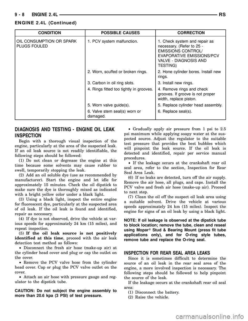
CONDITION POSSIBLE CAUSES CORRECTION
OIL CONSUMPTION OR SPARK
PLUGS FOULED1. PCV system malfunction. 1. Check system and repair as
necessary. (Refer to 25 -
EMISSIONS CONTROL/
EVAPORATIVE EMISSIONS/PCV
VALVE - DIAGNOSIS AND
TESTING)
2. Worn, scuffed or broken rings. 2. Hone cylinder bores. Install new
rings.
3. Carbon in oil ring slots. 3. Install new rings.
4. Rings fitted too tightly in grooves. 4. Remove rings and check
grooves. If groove is not proper
width, replace piston.
5. Worn valve guide(s). 5. Replace cylinder head assembly.
6. Valve stem seal(s) worn or
damaged.6. Replace seal(s).
DIAGNOSIS AND TESTING - ENGINE OIL LEAK
INSPECTION
Begin with a thorough visual inspection of the
engine, particularly at the area of the suspected leak.
If an oil leak source is not readily identifiable, the
following steps should be followed:
(1) Do not clean or degrease the engine at this
time because some solvents may cause rubber to
swell, temporarily stopping the leak.
(2) Add an oil soluble dye (use as recommended by
manufacturer). Start the engine and let idle for
approximately 15 minutes. Check the oil dipstick to
make sure the dye is thoroughly mixed as indicated
with a bright yellow color under a black light.
(3) Using a black light, inspect the entire engine
for fluorescent dye, particularly at the suspected area
of oil leak. If the oil leak is found and identified,
repair as necessary.
(4) If dye is not observed, drive the vehicle at var-
ious speeds for approximately 24 km (15 miles), and
repeat inspection.
(5)If the oil leak source is not positively
identified at this time, proceed with the air leak
detection test method as follows:
²Disconnect the fresh air hose (make-up air) at
the cylinder head cover and plug or cap the outlet on
the cover.
²Remove the PCV valve hose from the cylinder
head cover. Cap or plug the PCV valve outlet on the
cover.
²Attach an air hose with pressure gauge and reg-
ulator to the dipstick tube.
CAUTION: Do not subject the engine assembly to
more than 20.6 kpa (3 PSI) of test pressure.²Gradually apply air pressure from 1 psi to 2.5
psi maximum while applying soapy water at the sus-
pected source. Adjust the regulator to the suitable
test pressure that provides the best bubbles which
will pinpoint the leak source. If the oil leak is
detected and identified, repair per service manual
procedures.
²If the leakage occurs at the crankshaft rear oil
seal area, refer to the section, Inspection for Rear
Seal Area Leak.
(6) If no leaks are detected, turn off the air supply.
Remove the air hose, all plugs, and caps. Install the
PCV valve and fresh air hose (make-up air). Proceed
to next step.
(7) Clean the oil off the suspect oil leak area using
a suitable solvent. Drive the vehicle at various
speeds approximately 24 km (15 miles). Inspect the
engine for signs of an oil leak by using a black light.
NOTE: If oil leakage is observed at the dipstick tube
to block location; remove the tube, clean and reseal
using MoparTStud & Bearing Mount (press fit tube
applications only), and for O-ring style tubes,
remove tube and replace the O-ring seal.
INSPECTION FOR REAR SEAL AREA LEAKS
Since it is sometimes difficult to determine the
source of an oil leak in the rear seal area of the
engine, a more involved inspection is necessary. The
following steps should be followed to help pinpoint
the source of the leak.
If the leakage occurs at the crankshaft rear oil seal
area:
(1) Disconnect the battery.
(2) Raise the vehicle.
9 - 8 ENGINE 2.4LRS
ENGINE 2.4L (Continued)
Page 1191 of 2339
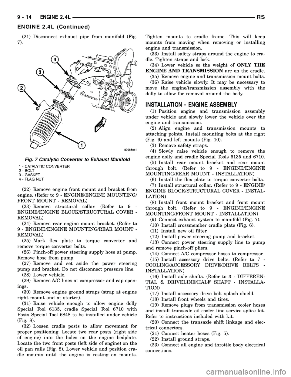
(21) Disconnect exhaust pipe from manifold (Fig.
7).
(22) Remove engine front mount and bracket from
engine. (Refer to 9 - ENGINE/ENGINE MOUNTING/
FRONT MOUNT - REMOVAL)
(23) Remove structural collar. (Refer to 9 -
ENGINE/ENGINE BLOCK/STRUCTURAL COVER -
REMOVAL)
(24) Remove rear engine mount bracket. (Refer to
9 - ENGINE/ENGINE MOUNTING/REAR MOUNT -
REMOVAL)
(25) Mark flex plate to torque converter and
remove torque converter bolts.
(26) Pinch-off power steering supply hose at pump.
Remove hose from pump.
(27) Remove and set aside the power steering
pump and bracket. Do not disconnect pressure line.
(28) Lower vehicle.
(29) Remove A/C lines at compressor and cap open-
ings.
(30) Remove engine ground straps (strap at engine
right mount and at starter).
(31) Raise vehicle enough to allow engine dolly
Special Tool 6135, cradle Special Tool 6710 with
Posts Special Tool 6848 to be installed under vehicle
(Fig. 8).
(32) Loosen cradle posts to allow movement for
proper positioning. Locate two rear posts (right side
of engine) into the holes on the engine bedplate.
Locate the two front posts (left side of engine) on the
oil pan rails (Fig. 8). Lower vehicle and position cra-
dle mounts until the engine is resting on mounts.Tighten mounts to cradle frame. This will keep
mounts from moving when removing or installing
engine and transmission.
(33) Install safety straps around the engine to cra-
dle. Tighten straps and lock.
(34) Lower vehicle so the weight ofONLY THE
ENGINE AND TRANSMISSIONare on the cradle.
(35) Remove engine and transmission mount bolts.
(36) Raise vehicle slowly. It may be necessary to
move the engine/transmission assembly with the
dolly to allow for removal around the body.
INSTALLATION - ENGINE ASSEMBLY
(1) Position engine and transmission assembly
under vehicle and slowly lower the vehicle over the
engine and transmission.
(2) Align engine and transmission mounts to
attaching points. Install mounting bolts at the right
(Fig. 9) and left mounts (Fig. 10).
(3) Remove safety straps.
(4) Slowly raise vehicle enough to remove the
engine dolly and cradle Special Tools 6135 and 6710.
(5) Install rear mount bracket and rear mount
through bolt. (Refer to 9 - ENGINE/ENGINE
MOUNTING/REAR MOUNT - INSTALLATION)
(6) Install the flex plate to torque converter bolts.
(7) Install structural collar. (Refer to 9 - ENGINE/
ENGINE BLOCK/STRUCTURAL COVER - INSTAL-
LATION)
(8) Install front mount bracket and front mount
through bolt. (Refer to 9 - ENGINE/ENGINE
MOUNTING/FRONT MOUNT - INSTALLATION)
(9) Connect exhaust system to manifold (Fig. 7).
(10) Install crossmember cradle plate (Fig. 6).
(11) Install new oil filter.
(12) Install power steering pump and bracket.
(13) Connect power steering supply line to pump
and remove pinch-off pliers.
(14) Connect A/C compressor hoses to compressor.
(15) Install accessory drive belts. (Refer to 7 -
COOLING/ACCESSORY DRIVE/DRIVE BELTS -
INSTALLATION)
(16) Install axle shafts. (Refer to 3 - DIFFEREN-
TIAL & DRIVELINE/HALF SHAFT - INSTALLA-
TION)
(17) Install accessory drive belt splash shield.
(18) Install front wheels and tires.
(19) Remove plugs from transmission cooler hoses
and install transaxle oil cooler line service splice kit.
Refer to instructions included with kit.
(20) Connect the transaxle shift linkage and elec-
trical connectors.
(21) Connect heater hoses (Fig. 5).
(22) Install ground straps.
(23) Connect all engine and throttle body electrical
connections.
Fig. 7 Catalytic Converter to Exhaust Manifold
1 - CATALYTIC CONVERTER
2 - BOLT
3 - GASKET
4 - FLAG NUT
9 - 14 ENGINE 2.4LRS
ENGINE 2.4L (Continued)
Page 1211 of 2339
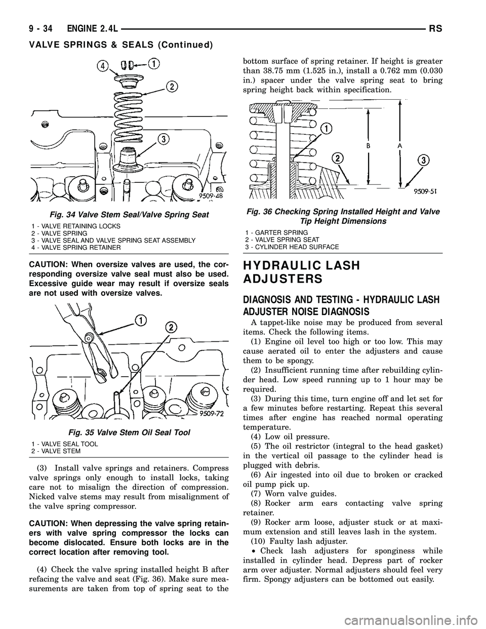
CAUTION: When oversize valves are used, the cor-
responding oversize valve seal must also be used.
Excessive guide wear may result if oversize seals
are not used with oversize valves.
(3) Install valve springs and retainers. Compress
valve springs only enough to install locks, taking
care not to misalign the direction of compression.
Nicked valve stems may result from misalignment of
the valve spring compressor.
CAUTION: When depressing the valve spring retain-
ers with valve spring compressor the locks can
become dislocated. Ensure both locks are in the
correct location after removing tool.
(4) Check the valve spring installed height B after
refacing the valve and seat (Fig. 36). Make sure mea-
surements are taken from top of spring seat to thebottom surface of spring retainer. If height is greater
than 38.75 mm (1.525 in.), install a 0.762 mm (0.030
in.) spacer under the valve spring seat to bring
spring height back within specification.HYDRAULIC LASH
ADJUSTERS
DIAGNOSIS AND TESTING - HYDRAULIC LASH
ADJUSTER NOISE DIAGNOSIS
A tappet-like noise may be produced from several
items. Check the following items.
(1) Engine oil level too high or too low. This may
cause aerated oil to enter the adjusters and cause
them to be spongy.
(2) Insufficient running time after rebuilding cylin-
der head. Low speed running up to 1 hour may be
required.
(3) During this time, turn engine off and let set for
a few minutes before restarting. Repeat this several
times after engine has reached normal operating
temperature.
(4) Low oil pressure.
(5) The oil restrictor (integral to the head gasket)
in the vertical oil passage to the cylinder head is
plugged with debris.
(6) Air ingested into oil due to broken or cracked
oil pump pick up.
(7) Worn valve guides.
(8) Rocker arm ears contacting valve spring
retainer.
(9) Rocker arm loose, adjuster stuck or at maxi-
mum extension and still leaves lash in the system.
(10) Faulty lash adjuster.
²Check lash adjusters for sponginess while
installed in cylinder head. Depress part of rocker
arm over adjuster. Normal adjusters should feel very
firm. Spongy adjusters can be bottomed out easily.
Fig. 34 Valve Stem Seal/Valve Spring Seat
1 - VALVE RETAINING LOCKS
2 - VALVE SPRING
3 - VALVE SEAL AND VALVE SPRING SEAT ASSEMBLY
4 - VALVE SPRING RETAINER
Fig. 35 Valve Stem Oil Seal Tool
1 - VALVE SEAL TOOL
2 - VALVE STEM
Fig. 36 Checking Spring Installed Height and Valve
Tip Height Dimensions
1 - GARTER SPRING
2 - VALVE SPRING SEAT
3 - CYLINDER HEAD SURFACE
9 - 34 ENGINE 2.4LRS
VALVE SPRINGS & SEALS (Continued)
Page 1213 of 2339

(4) Install spark plugs.
(5) Install cylinder head cover. (Refer to 9 -
ENGINE/CYLINDER HEAD/CYLINDER HEAD
COVER(S) - INSTALLATION)
ENGINE BLOCK
DESCRIPTION
The cast iron cylinder block is a two-piece assem-
bly, consisting of the cylinder block and bed plate
(Fig. 40). The bed plate incorporates the main bear-
ing caps and bolts to the cylinder block. This design
offers a much stronger lower end and increased cyl-
inder block rigidity. The rear oil seal retainer is inte-
gral with the block. The bed plate and block are
serviced as an assembly.
STANDARD PROCEDURE - CYLINDER BORE
HONING
(1) Used carefully, the cylinder bore resizing hone,
recommended tool C-823 or equivalent, equipped
with 220 grit stones, is the best tool for this honing
procedure. In addition to deglazing, it will reducetaper and out-of-round as well as removing light
scuffing, scoring or scratches. Usually a few strokes
will clean up a bore and maintain the required lim-
its.
(2) Deglazing of the cylinder walls may be done
using a cylinder surfacing hone, recommended tool
C-3501 or equivalent, equipped with 280 grit stones,
if the cylinder bore is straight and round. 20±60
strokes depending on the bore condition, will be suf-
ficient to provide a satisfactory surface. Use a light
honing oil.Do not use engine or transmission oil,
mineral spirits or kerosene.Inspect cylinder walls
after each 20 strokes.
(3) Honing should be done by moving the hone up
and down fast enough to get a cross-hatch pattern.
When hone marksintersectat 40-60 degrees, the
cross hatch angle is most satisfactory for proper seat-
ing of rings (Fig. 41).
(4) A controlled hone motor speed between
200±300 RPM is necessary to obtain the proper cross-
hatch angle. The number of up and down strokes per
minute can be regulated to get the desired 40±60
degree angle. Faster up and down strokes increase
the cross-hatch angle.
(5) After honing, it is necessary that the block be
cleaned again to remove all traces of abrasive.
Fig. 39 Rocker Arm
1 - TIP
2 - LASH ADJUSTER POCKET
3 - ROLLER
Fig. 40 Cylinder Block and Bed plate
1 - CYLINDER BLOCK
2 - BED PLATE
Fig. 41 Cylinder Bore Cross-Hatch Pattern
1 - CROSS-HATCH PATTERN
2 - 40ɱ60É
9 - 36 ENGINE 2.4LRS
ROCKER ARMS (Continued)
Page 1231 of 2339
(6) Install oil pressure switch and connector. (Refer
to 9 - ENGINE/LUBRICATION/OIL PRESSURE
SENSOR/SWITCH - INSTALLATION)
OIL
STANDARD PROCEDURE
ENGINE OIL LEVEL CHECK
The best time to check engine oil level is after it
has sat overnight, or if the engine has been running,
allow the engine to be shut off for at least 5 minutes
before checking oil level.
Checking the oil while the vehicle is on level
ground will improve the accuracy of the oil level
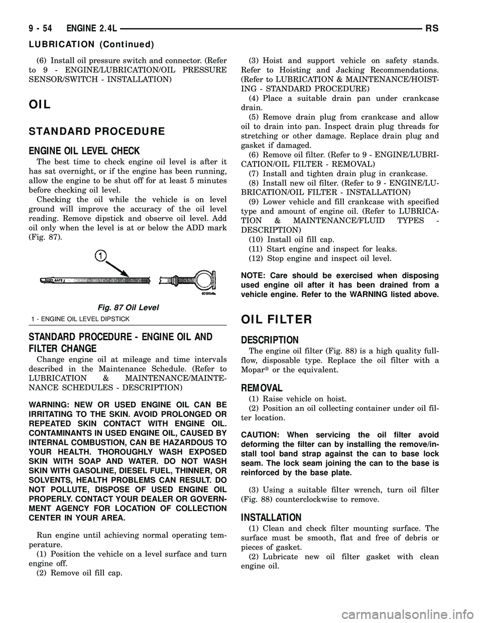
reading. Remove dipstick and observe oil level. Add
oil only when the level is at or below the ADD mark
(Fig. 87).
STANDARD PROCEDURE - ENGINE OIL AND
FILTER CHANGE
Change engine oil at mileage and time intervals
described in the Maintenance Schedule. (Refer to
LUBRICATION & MAINTENANCE/MAINTE-
NANCE SCHEDULES - DESCRIPTION)
WARNING: NEW OR USED ENGINE OIL CAN BE
IRRITATING TO THE SKIN. AVOID PROLONGED OR
REPEATED SKIN CONTACT WITH ENGINE OIL.
CONTAMINANTS IN USED ENGINE OIL, CAUSED BY
INTERNAL COMBUSTION, CAN BE HAZARDOUS TO
YOUR HEALTH. THOROUGHLY WASH EXPOSED
SKIN WITH SOAP AND WATER. DO NOT WASH
SKIN WITH GASOLINE, DIESEL FUEL, THINNER, OR
SOLVENTS, HEALTH PROBLEMS CAN RESULT. DO
NOT POLLUTE, DISPOSE OF USED ENGINE OIL
PROPERLY. CONTACT YOUR DEALER OR GOVERN-
MENT AGENCY FOR LOCATION OF COLLECTION
CENTER IN YOUR AREA.
Run engine until achieving normal operating tem-
perature.
(1) Position the vehicle on a level surface and turn
engine off.
(2) Remove oil fill cap.(3) Hoist and support vehicle on safety stands.
Refer to Hoisting and Jacking Recommendations.
(Refer to LUBRICATION & MAINTENANCE/HOIST-
ING - STANDARD PROCEDURE)
(4) Place a suitable drain pan under crankcase
drain.
(5) Remove drain plug from crankcase and allow
oil to drain into pan. Inspect drain plug threads for
stretching or other damage. Replace drain plug and
gasket if damaged.
(6) Remove oil filter. (Refer to 9 - ENGINE/LUBRI-
CATION/OIL FILTER - REMOVAL)
(7) Install and tighten drain plug in crankcase.
(8) Install new oil filter. (Refer to 9 - ENGINE/LU-
BRICATION/OIL FILTER - INSTALLATION)
(9) Lower vehicle and fill crankcase with specified
type and amount of engine oil. (Refer to LUBRICA-
TION & MAINTENANCE/FLUID TYPES -
DESCRIPTION)
(10) Install oil fill cap.
(11) Start engine and inspect for leaks.
(12) Stop engine and inspect oil level.
NOTE: Care should be exercised when disposing
used engine oil after it has been drained from a
vehicle engine. Refer to the WARNING listed above.
OIL FILTER
DESCRIPTION
The engine oil filter (Fig. 88) is a high quality full-
flow, disposable type. Replace the oil filter with a
Mopartor the equivalent.
REMOVAL
(1) Raise vehicle on hoist.
(2) Position an oil collecting container under oil fil-
ter location.
CAUTION: When servicing the oil filter avoid
deforming the filter can by installing the remove/in-
stall tool band strap against the can to base lock
seam. The lock seam joining the can to the base is
reinforced by the base plate.
(3) Using a suitable filter wrench, turn oil filter
(Fig. 88) counterclockwise to remove.
INSTALLATION
(1) Clean and check filter mounting surface. The
surface must be smooth, flat and free of debris or
pieces of gasket.
(2) Lubricate new oil filter gasket with clean
engine oil.
Fig. 87 Oil Level
1 - ENGINE OIL LEVEL DIPSTICK
9 - 54 ENGINE 2.4LRS
LUBRICATION (Continued)