LUG NUT CHRYSLER VOYAGER 2005 Workshop Manual
[x] Cancel search | Manufacturer: CHRYSLER, Model Year: 2005, Model line: VOYAGER, Model: CHRYSLER VOYAGER 2005Pages: 2339, PDF Size: 59.69 MB
Page 1411 of 2339

CONDITION POSSIBLE CAUSES CORRECTION
4. Loose lower control arm mounting
bolts at front suspension
crossmember.4. Tighten control arm mounting bolts to
the specified torques.
5. Lower control arm pivot bushing
worn.5. Replace lower control arm pivot
bushing.
6. Loose strut assembly mounting
fasteners at tower or knuckle.6. Tighten strut assembly fasteners to
the specified torque.
7. Power steering fluid hose touching
the body of the vehicle.7. Adjust hose to proper position by
loosening, repositioning, and tightening
attachments to specified torque. Do not
bend tubing.
8. Damaged front suspension
crossmember.8. Replace front suspension
crossmember.
9. Stabilizer bar link ball joints worn. 9. Replace stabilizer bar link.
10. Lug nuts loose. 10. Tighten lug nuts to specifications.
11. Excessive Wheel bearing
free-play.11. Verify correct halfshaft hub nut
torque. Replace hub and bearing if
torque is okay.
12. Internal power steering gear
noise.12. Replace power steering gear.
POPPING NOISE 1. Worn outer tie rod. 1. Check ball joint for free-play;
Replace outer tie rod.
2. Loose inner tie rod. 2. Replace power steering gear.
CHIRP OR SQUEAL
(POWER STEERING
PUMP)1. Loose power steering pump drive
belt.1. Check and adjust power steering
pump drive belt to specifications or
replace automatic tensioner where
applicable. Replace belt if worn or
glazed.
2. Malfuctioning belt auto-tensioner 2. Replace belt auto-tensioner.
WHINE, GROWL, MOAN
OR GROAN (POWER
STEERING PUMP)***1. Low fluid level. 1. Fill power steering fluid reservoir to
proper level and check for leaks (make
sure all air is bled from the system
fluid).
2. Power steering hose touching
vehicle body or frame.2. Adjust hose to proper position by
loosening, repositioning, and tightening
fitting to specified torque. Do not bend
tubing. Replace hose if damaged.
3. Extremely low ambient
temperature.3. Some noise can be expected, but will
go away as vehicle warms. Replace
pump if noise is excessive.
4. Extreme wear of power steering
pump internal components.4. Replace power steering pump and
flush system as necessary.
19 - 4 STEERINGRS
STEERING (Continued)
Page 1439 of 2339
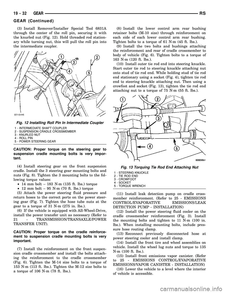
(3) Install Remover/Installer Special Tool 6831A
through the center of the roll pin, securing it with
the knurled nut (Fig. 12). Hold threaded rod station-
ary while turning nut, this will pull the roll pin into
the intermediate coupler.
CAUTION: Proper torque on the steering gear to
suspension cradle mounting bolts is very impor-
tant.
(4) Install steering gear on the front suspension
cradle. Install the 3 steering gear mounting bolts and
nuts (Fig. 8). Tighten the 3 mounting bolts to the fol-
lowing torque values:
²14 mm bolt ± 183 N´m (135 ft. lbs.) torque
²12 mm bolt ± 95 N´m (70 ft. lbs.) torque
(5) Attach the power steering fluid pressure and
return hoses to the correct ports on the power steer-
ing gear (Fig. 7). Tighten the hose tube nuts at the
gear to a torque of 31 N´m (275 in. lbs.).
(6) If the vehicle is equipped with All-Wheel-Drive,
install the power transfer unit as necessary (Refer to
21 - TRANSMISSION/TRANSAXLE/POWER
TRANSFER UNIT).
CAUTION: Proper torque on the cradle reinforce-
ment to suspension cradle mounting bolts is very
important.
(7) Install the reinforcement on the front suspen-
sion cradle crossmember and install the bolts attach-
ing the reinforcement to the cradle crossmember
(Fig. 6). Tighten the M-14 size bolts to a torque of
153 N´m (113 ft. lbs.). Tighten the M-12 size bolts to
a torque of 106 N´m (78 ft. lbs.).(8) Install the lower control arm rear bushing
retainer bolts (M-10 size) through reinforcement on
each side of each lower control arm rear bushing.
Tighten bolts to a torque of 61 N´m (45 ft. lbs.).
(9) Install the two bolts and bushings attaching
the reinforcement and rear of cradle crossmember to
body of vehicle (Fig. 6). Tighten bolts to a torque of
163 N´m (120 ft. lbs.).
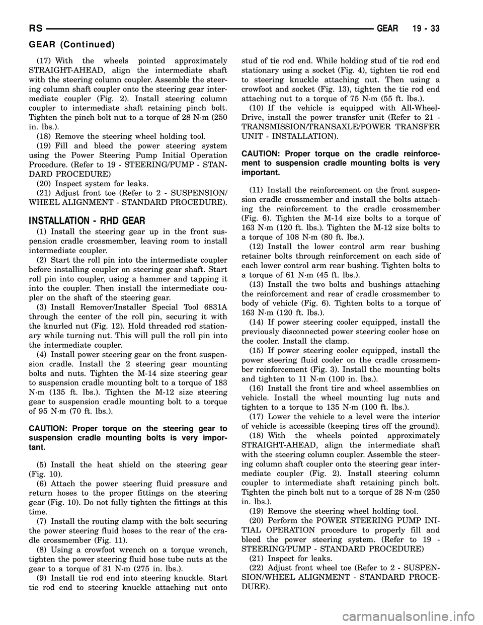
(10) Install outer tie rod end into steering knuckle.
Start outer tie rod to steering knuckle attaching nut
onto stud of tie rod end. While holding stud of tie rod
end stationary using a socket (Fig. 4), tighten tie rod
end to steering knuckle attaching nut. Then using a
crowfoot and socket (Fig. 13), tighten the tie rod end
attaching nut to a torque of 75 N´m (55 ft. lbs.).
(11) Install leak detection pump on cradle cross-
member reinforcement. (Refer to 25 - EMISSIONS
CONTROL/EVAPORATIVE EMISSIONS/LEAK
DETECTION PUMP - INSTALLATION)
(12) Install the power steering fluid cooler on the
cradle crossmember reinforcement (Fig. 3). Install
the mounting bolts and tighten to 11 N´m (100 in.
lbs.). When installing mounting bolts, include pres-
sure hose routing clamp.
(13) Reconnect previously disconnected hose at
power steering cooler and install clamp.
(14) Install the front tire and wheel assemblies on
vehicle. Install the wheel lug nuts and torque to 135
N´m (100 ft. lbs.).
(15) Install front emissions vapor canister. (Refer
to 25 - EMISSIONS CONTROL/EVAPORATIVE
EMISSIONS/VAPOR CANISTER - INSTALLATION)
(16) Lower the vehicle to a level where the interior
of vehicle is accessible.
Fig. 12 Installing Roll Pin In Intermediate Coupler
1 - INTERMEDIATE SHAFT COUPLER
2 - SUSPENSION CRADLE CROSSMEMBER
3 - KNURLED NUT
4 - ROLL PIN
5 - POWER STEERING GEAR
Fig. 13 Torquing Tie Rod End Attaching Nut
1 - STEERING KNUCKLE
2 - TIE ROD END
3 - CROWFOOT
4 - SOCKET
5 - TORQUE WRENCH
19 - 32 GEARRS
GEAR (Continued)
Page 1440 of 2339
(17) With the wheels pointed approximately
STRAIGHT-AHEAD, align the intermediate shaft
with the steering column coupler. Assemble the steer-
ing column shaft coupler onto the steering gear inter-
mediate coupler (Fig. 2). Install steering column
coupler to intermediate shaft retaining pinch bolt.
Tighten the pinch bolt nut to a torque of 28 N´m (250
in. lbs.).
(18) Remove the steering wheel holding tool.
(19) Fill and bleed the power steering system
using the Power Steering Pump Initial Operation
Procedure. (Refer to 19 - STEERING/PUMP - STAN-
DARD PROCEDURE)
(20) Inspect system for leaks.
(21) Adjust front toe (Refer to 2 - SUSPENSION/
WHEEL ALIGNMENT - STANDARD PROCEDURE).
INSTALLATION - RHD GEAR
(1) Install the steering gear up in the front sus-
pension cradle crossmember, leaving room to install
intermediate coupler.
(2) Start the roll pin into the intermediate coupler
before installing coupler on steering gear shaft. Start
roll pin into coupler, using a hammer and tapping it
into the coupler. Then install the intermediate cou-
pler on the shaft of the steering gear.
(3) Install Remover/Installer Special Tool 6831A
through the center of the roll pin, securing it with
the knurled nut (Fig. 12). Hold threaded rod station-
ary while turning nut. This will pull the roll pin into
the intermediate coupler.
(4) Install power steering gear on the front suspen-
sion cradle. Install the 2 steering gear mounting
bolts and nuts. Tighten the M-14 size steering gear
to suspension cradle mounting bolt to a torque of 183
N´m (135 ft. lbs.). Tighten the M-12 size steering
gear to suspension cradle mounting bolt to a torque
of 95 N´m (70 ft. lbs.).
CAUTION: Proper torque on the steering gear to
suspension cradle mounting bolts is very impor-
tant.
(5) Install the heat shield on the steering gear
(Fig. 10).
(6) Attach the power steering fluid pressure and
return hoses to the proper fittings on the steering
gear (Fig. 10). Do not fully tighten the fittings at this
time.
(7) Install the routing clamp with the bolt securing
the power steering fluid hoses to the rear of the cra-
dle crossmember (Fig. 11).
(8) Using a crowfoot wrench on a torque wrench,
tighten the power steering fluid hose tube nuts at the
gear to a torque of 31 N´m (275 in. lbs.).
(9) Install tie rod end into steering knuckle. Start
tie rod end to steering knuckle attaching nut ontostud of tie rod end. While holding stud of tie rod end
stationary using a socket (Fig. 4), tighten tie rod end
to steering knuckle attaching nut. Then using a
crowfoot and socket (Fig. 13), tighten the tie rod end
attaching nut to a torque of 75 N´m (55 ft. lbs.).
(10) If the vehicle is equipped with All-Wheel-
Drive, install the power transfer unit (Refer to 21 -
TRANSMISSION/TRANSAXLE/POWER TRANSFER
UNIT - INSTALLATION).
CAUTION: Proper torque on the cradle reinforce-
ment to suspension cradle mounting bolts is very
important.
(11) Install the reinforcement on the front suspen-
sion cradle crossmember and install the bolts attach-
ing the reinforcement to the cradle crossmember
(Fig. 6). Tighten the M-14 size bolts to a torque of
163 N´m (120 ft. lbs.). Tighten the M-12 size bolts to
a torque of 108 N´m (80 ft. lbs.).
(12) Install the lower control arm rear bushing
retainer bolts through reinforcement on each side of
each lower control arm rear bushing. Tighten bolts to
a torque of 61 N´m (45 ft. lbs.).
(13) Install the two bolts and bushings attaching
the reinforcement and rear of cradle crossmember to
body of vehicle (Fig. 6). Tighten bolts to a torque of
163 N´m (120 ft. lbs.).
(14) If power steering cooler equipped, install the
previously disconnected power steering cooler hose on
the cooler. Install the clamp.
(15) If power steering cooler equipped, install the
power steering fluid cooler on the cradle crossmem-
ber reinforcement (Fig. 3). Install the mounting bolts
and tighten to 11 N´m (100 in. lbs.).
(16) Install the front tire and wheel assemblies on
vehicle. Install the wheel mounting lug nuts and
tighten to a torque to 135 N´m (100 ft. lbs.).
(17) Lower the vehicle to a level were the interior
of vehicle is accessible (keeping tires off the ground).
(18) With the wheels pointed approximately
STRAIGHT-AHEAD, align the intermediate shaft
with the steering column coupler. Assemble the steer-
ing column shaft coupler onto the steering gear inter-
mediate coupler (Fig. 2). Install steering column
coupler to intermediate shaft retaining pinch bolt.
Tighten the pinch bolt nut to a torque of 28 N´m (250
in. lbs.).
(19) Remove the steering wheel holding tool.
(20) Perform the POWER STEERING PUMP INI-
TIAL OPERATION procedure to properly fill and
bleed the power steering system. (Refer to 19 -
STEERING/PUMP - STANDARD PROCEDURE)
(21) Inspect for leaks.
(22) Adjust front wheel toe (Refer to 2 - SUSPEN-
SION/WHEEL ALIGNMENT - STANDARD PROCE-
DURE).
RSGEAR19-33
GEAR (Continued)
Page 1775 of 2339
CLEANING - TIRES
Before delivery of a vehicle, remove the protective
coating on the tires with white sidewalls or raised
white letters. To remove the protective coating, apply
warm water and let it soak for a few minutes. After-
wards, scrub the coating away with a soft bristle
brush. Steam cleaning may also be used to remove
the coating.
CAUTION: DO NOT use gasoline, mineral oil, oil-
based solvent or a wire brush for cleaning.
WHEELS
DESCRIPTION - WHEEL
Original equipment wheels are designed for proper
operation at all loads up to the specified maximum
vehicle capacity.
All models use either steel or aluminum drop-cen-
ter wheels. Every wheel has raised sections between
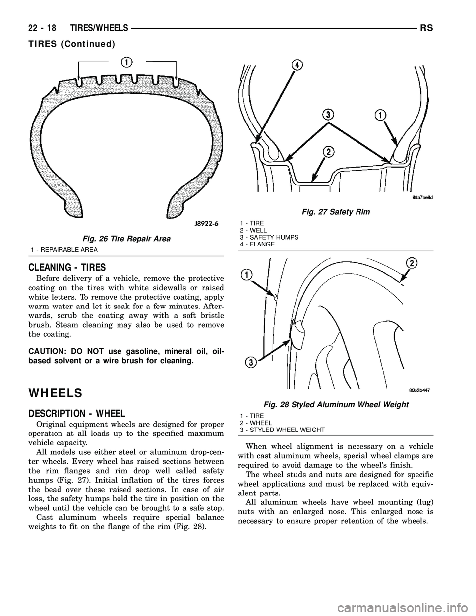
the rim flanges and rim drop well called safety
humps (Fig. 27). Initial inflation of the tires forces
the bead over these raised sections. In case of air
loss, the safety humps hold the tire in position on the
wheel until the vehicle can be brought to a safe stop.
Cast aluminum wheels require special balance
weights to fit on the flange of the rim (Fig. 28).When wheel alignment is necessary on a vehicle
with cast aluminum wheels, special wheel clamps are
required to avoid damage to the wheel's finish.
The wheel studs and nuts are designed for specific
wheel applications and must be replaced with equiv-
alent parts.
All aluminum wheels have wheel mounting (lug)
nuts with an enlarged nose. This enlarged nose is
necessary to ensure proper retention of the wheels.
Fig. 26 Tire Repair Area
1 - REPAIRABLE AREA
Fig. 27 Safety Rim
1 - TIRE
2 - WELL
3 - SAFETY HUMPS
4 - FLANGE
Fig. 28 Styled Aluminum Wheel Weight
1 - TIRE
2 - WHEEL
3 - STYLED WHEEL WEIGHT
22 - 18 TIRES/WHEELSRS
TIRES (Continued)
Page 1776 of 2339
DIAGNOSIS AND TESTING - WHEEL
INSPECTION
Inspect wheels for:
²Excessive runout
²Dents, cracks or irregular bends
²Damaged wheel stud (lug) holes
²Air Leaks
NOTE: Do not attempt to repair a wheel by hammer-
ing, heating or welding.
If a wheel is damaged, an original equipment
replacement wheel should be used. When obtaining
replacement wheels, they must be equivalent in load
carrying capacity. The diameter, width, offset, pilot
hole and bolt circle of the wheel should be the same
as the original wheel.
WARNING: FAILURE TO USE EQUIVALENT
REPLACEMENT WHEELS MAY ADVERSELY
AFFECT THE SAFETY AND HANDLING OF THE
VEHICLE.
WARNING: REPLACEMENT WITH USED WHEELS IS
NOT RECOMMENDED. THE SERVICE HISTORY OF
THE WHEEL MAY HAVE INCLUDED SEVERE TREAT-
MENT OR VERY HIGH MILEAGE. THE RIM COULD
FAIL WITHOUT WARNING.
CLEANING
WHEEL AND WHEEL TRIM CARE
All wheels and wheel trim, especially aluminum
and chrome plated, should be cleaned regularly using
mild soap and water to maintain their luster and to
prevent corrosion. Wash them with the same soap
solution recommended for the body of the vehicle.
When cleaning extremely dirty wheels, care must
be taken in the selection of tire and wheel cleaning
chemicals and equipment to prevent damage to the
wheels. MopartWheel Treatment or MopartChrome
Cleaner is recommended. Any of the ªDO NOT USEº
items listed below can damage wheels and wheel
trim.DO NOT USE:
²Any abrasive cleaner
²Any abrasive cleaning pad (such as steel wool)
or abrasive brush
²Any cleaner that contains an acid which can
react with and discolor the chrome surface.Many
wheel cleaners contain acids that can harm the
wheel surface.
²Oven cleaner
²A car wash that uses carbide-tipped wheel clean-
ing brushes or acidic solutions.
SPECIFICATIONS
WHEEL
SPECIFICATIONS
DESCRIPTION SPECIFICATION
Wheel Mounting (Lug)
Nut Hex Size19 mm
Wheel Mounting Stud
SizeM12 x 1.5 mm
TORQUE SPECIFICATIONS
DESCRIPTION N´mFt.
Lbs.In.
Lbs.
TPM Sensor Mounting Nut 4 Ð 35
Wheel Mounting (Lug ) Nut 135 100 Ð
WHEEL COVER
DESCRIPTION
This vehicle uses a bolt-on type wheel cover (Fig.
29).
This bolt-on wheel cover cannot be removed from
the wheel until three of the five wheel mounting nuts
shown are removed (Fig. 29). The bolt-on wheel cover
can then be removed with the remaining two wheel
nuts tightened in place.
REMOVAL
(1) Noting the location of the valve stem in rela-
tionship to the wheel mounting nuts, remove the
three wheel mounting nuts securing the wheel cover
to the wheel and hub (Fig. 29).
CAUTION: When removing the wheel cover, do not
pry the wheel cover from the wheel. This can result
in damage to the wheel cover. The wheel cover is
removed by pulling it off the wheel by hand.
RSTIRES/WHEELS22-19
WHEELS (Continued)
Page 1778 of 2339
WHEEL MOUNTING STUDS -
FRONT
REMOVAL
NOTE: Before proceeding, (Refer to 5 - BRAKES -
WARNING)(Refer to 5 - BRAKES - CAUTION).
CAUTION: Wheel mounting studs MUST NOT be
hammered out of hub flange of hub and bearing
assembly. If a stud is removed by hammering it out,
damage to hub and bearing assembly will occur
leading to premature bearing failure.
(1) Raise vehicle. (Refer to LUBRICATION &
MAINTENANCE/HOISTING - STANDARD PROCE-
DURE)
(2) Remove front wheel and tire assembly. (Refer
to 22 - TIRES/WHEELS - REMOVAL)
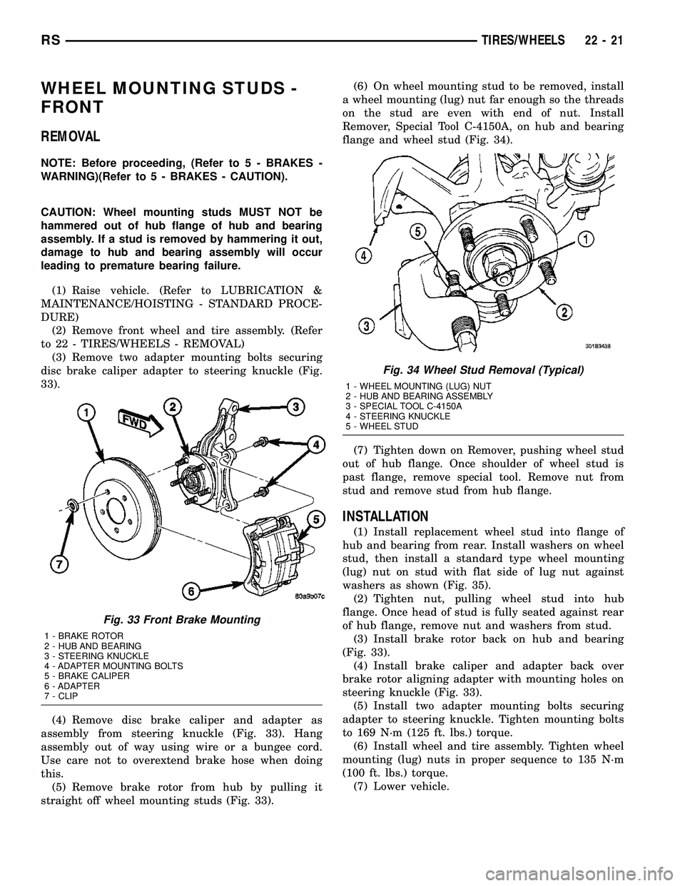
(3) Remove two adapter mounting bolts securing
disc brake caliper adapter to steering knuckle (Fig.
33).
(4) Remove disc brake caliper and adapter as
assembly from steering knuckle (Fig. 33). Hang
assembly out of way using wire or a bungee cord.
Use care not to overextend brake hose when doing
this.
(5) Remove brake rotor from hub by pulling it
straight off wheel mounting studs (Fig. 33).(6) On wheel mounting stud to be removed, install
a wheel mounting (lug) nut far enough so the threads
on the stud are even with end of nut. Install
Remover, Special Tool C-4150A, on hub and bearing
flange and wheel stud (Fig. 34).
(7) Tighten down on Remover, pushing wheel stud
out of hub flange. Once shoulder of wheel stud is
past flange, remove special tool. Remove nut from
stud and remove stud from hub flange.
INSTALLATION
(1) Install replacement wheel stud into flange of
hub and bearing from rear. Install washers on wheel
stud, then install a standard type wheel mounting
(lug) nut on stud with flat side of lug nut against
washers as shown (Fig. 35).
(2) Tighten nut, pulling wheel stud into hub
flange. Once head of stud is fully seated against rear
of hub flange, remove nut and washers from stud.
(3) Install brake rotor back on hub and bearing
(Fig. 33).
(4) Install brake caliper and adapter back over
brake rotor aligning adapter with mounting holes on
steering knuckle (Fig. 33).
(5) Install two adapter mounting bolts securing
adapter to steering knuckle. Tighten mounting bolts
to 169 N´m (125 ft. lbs.) torque.
(6) Install wheel and tire assembly. Tighten wheel
mounting (lug) nuts in proper sequence to 135 N´m
(100 ft. lbs.) torque.
(7) Lower vehicle.
Fig. 33 Front Brake Mounting
1 - BRAKE ROTOR
2 - HUB AND BEARING
3 - STEERING KNUCKLE
4 - ADAPTER MOUNTING BOLTS
5 - BRAKE CALIPER
6 - ADAPTER
7 - CLIP
Fig. 34 Wheel Stud Removal (Typical)
1 - WHEEL MOUNTING (LUG) NUT
2 - HUB AND BEARING ASSEMBLY
3 - SPECIAL TOOL C-4150A
4 - STEERING KNUCKLE
5 - WHEEL STUD
RSTIRES/WHEELS22-21
Page 1779 of 2339
(8) Road test vehicle to ensure proper operation of
the brakes.
WHEEL MOUNTING STUDS -
REAR
REMOVAL
CAUTION: If a wheel attaching stud needs to be
replaced in the hub and bearing assembly the studs
MUST NOT be hammered out of the hub flange. If a
stud is removed by hammering it out of the bearing
flange, damage to the hub and bearing assembly
will occur leading to premature hub and bearing
failure.
(1) Raise vehicle on jackstands or centered on a
frame contact type hoist. See Hoisting in Lubrication
and Maintenance.
(2) Remove the rear wheel and tire assembly.
(3) Remove the brake drum or disc brake caliper
and rotor. Refer to Brakes.
(4) Install a lug nut on the wheel stud to be
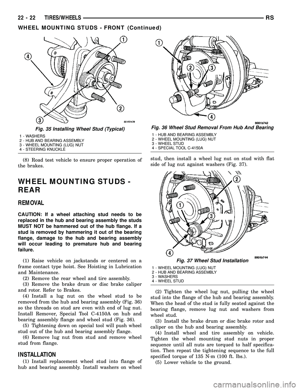
removed from the hub and bearing assembly (Fig. 36)
so the threads on stud are even with end of lug nut.
Install Remover, Special Tool C-4150A on hub and
bearing assembly flange and wheel stud (Fig. 36).
(5)
Tightening down on special tool will push wheel
stud out of the hub and bearing assembly flange.
(6) Remove lug nut from stud and remove wheel
stud from flange.
INSTALLATION
(1) Install replacement wheel stud into flange of
hub and bearing assembly. Install washers on wheelstud, then install a wheel lug nut on stud with flat
side of lug nut against washers (Fig. 37).
(2) Tighten the wheel lug nut, pulling the wheel
stud into the flange of the hub and bearing assembly.
When the head of the stud is fully seated against the
bearing flange, remove lug nut and washers from
wheel stud.
(3) Install the brake drum or disc brake rotor and
caliper on the hub and bearing assembly.
(4) Install wheel and tire assembly on vehicle.
Tighten the wheel mounting stud nuts in proper
sequence until all nuts are torqued to half specifica-
tion. Then repeat the tightening sequence to the full
specified torque of 135 N´m (100 ft. lbs.).
(5) Lower vehicle to the ground.
Fig. 35 Installing Wheel Stud (Typical)
1 - WASHERS
2 - HUB AND BEARING ASSEMBLY
3 - WHEEL MOUNTING (LUG) NUT
4 - STEERING KNUCKLE
Fig. 36 Wheel Stud Removal From Hub And Bearing
1 - HUB AND BEARING ASSEMBLY
2 - WHEEL MOUNTING (LUG) NUT
3 - WHEEL STUD
4 - SPECIAL TOOL C-4150A
Fig. 37 Wheel Stud Installation
1 - WHEEL MOUNTING (LUG) NUT
2 - HUB AND BEARING ASSEMBLY
3 - WASHERS
4 - WHEEL STUD
22 - 22 TIRES/WHEELSRS
WHEEL MOUNTING STUDS - FRONT (Continued)
Page 1790 of 2339

DESCRIPTION N´m Ft. Lbs. In. Lbs.
Front cover to seat track screws 4 Ð 32
Front door hinge to hinge pillar bolts 34 25 Ð
Front door hinge to door nuts and bolts 34 25 Ð
Front door latch striker bolts 28 21 Ð
Front/quad seat cushion bolts 28.5 21 Ð
Front seat belt retractor bolts 38 28 Ð
Front seat riser to floor nuts 60 44 Ð
Front seat track cover screws 4 Ð 35
Front seat riser to seat track nuts 81 60 Ð
Front seatback pivot bolts 54 40 Ð
Front seatback recliner nut 12 Ð 105
Front seatback assist strap screws 2.5 Ð 22
Grocery bag holder screws 2 Ð 17
Hinge to liftgate bolts 33 24 Ð
Hood latch to bolts 13.5 10 Ð
Hood latch striker bolts 13.5 10 Ð
Hood hinge to hood bolts 13.5 10 Ð
Liftgate exterior handle outer screws 20 15 Ð
Liftgate exterior handle inner bolts 40 30 Ð
Lifgate hinge to roof header bolts 33 24 Ð
Liftgate latch bolts 16 12 Ð
Liftgate latch striker bolts 28 21 Ð
Liftgate lift motor link to liftgate 28 21 Ð
Liftgate spoiler bolts 9 Ð 80
Lifgate stabilizer wedge striker to D-pillar bolts 3 Ð 30
Luggage rack crossbar fasteners 4 Ð 35
Lumbar support handle screw 1 Ð 9
Pivot bolt to the body half of hood hinge 28 21 Ð
Prop assembly to lifgate bolts 28 21 Ð
Rear door glass to regulator bolt 11 8 Ð
Rear door hinge to B-pillar bolt 28 20 Ð
Rear door hinge to door bolt 28 20 Ð
Rear door latch striker 28 20 Ð
Rear latch to sliding door end frame 28 20 Ð
Rear seat back to seat cushion bolt 27 19 Ð
Recliner to seat back frame 12 9 Ð
Seatback frame upper rail 8 Ð 71
Seatback hinge bolt 48 35 Ð
Seatback hinge cover screws 2.3 Ð 20
Shoulder belt turning loop onto height adjuster 39 29 Ð
Side view mirror bolts 10 Ð 85
Sliding door center hinge adjusting bolt 15 Ð 130
RSBODY23-11
BODY (Continued)
Page 1810 of 2339
(4) Check door for height using character lines as
a reference. Also check roof contour as a controlling
factor.
Using the procedures noted below, adjust the side
door in the order the individual steps are called out.
DOOR FLUSHNESS ADJUSTMENT
(1) Check sliding door flushness at the C-pillar
striker.
(2) If the sliding door is under or over flush,
remove striker assembly and move thread plate over
keeping one bolt in plate so it will not fall between
inner and outer panels.
(3) Adjust the C-pillar striker in or out until the
door is flush. Then, the on size hole can be elongated
in the direction required. This can be done by grind-
ing or filing the sheet metal and then painting raw
edge to prevent rusting.
(4) Check upper B-pillar flushness to A-pillar
cover.
(5) The sliding door upper hinge can only be
moved outboard by addinga1mmshim behind the
hinge mounting area once the two attachment bolts
are removed and reinstalled.
(6) Check flushness at upper C-pillar.
(7) If upper C-pillar flushness is out of specifica-
tion use a heavy rubber mallet on the door assembly
until door is in specifications.
DOOR GAP ADJUSTMENT - UP/DOWN
(1) Check height of sliding door at the B-pillar and
C-pillar to determine which area is contributing the
greatest to the incorrect gaps.
(2) Visually inspect the sliding door for fitting low
at the top of the door by checking the alignment of
the top contour of the door to the quarter panel.
(3) If the sliding door is high at the C-pillar.
(a) Open the door to mid-point of travel.
(b) Mark outline of center hinge on sliding door
to assist in making adjustments.
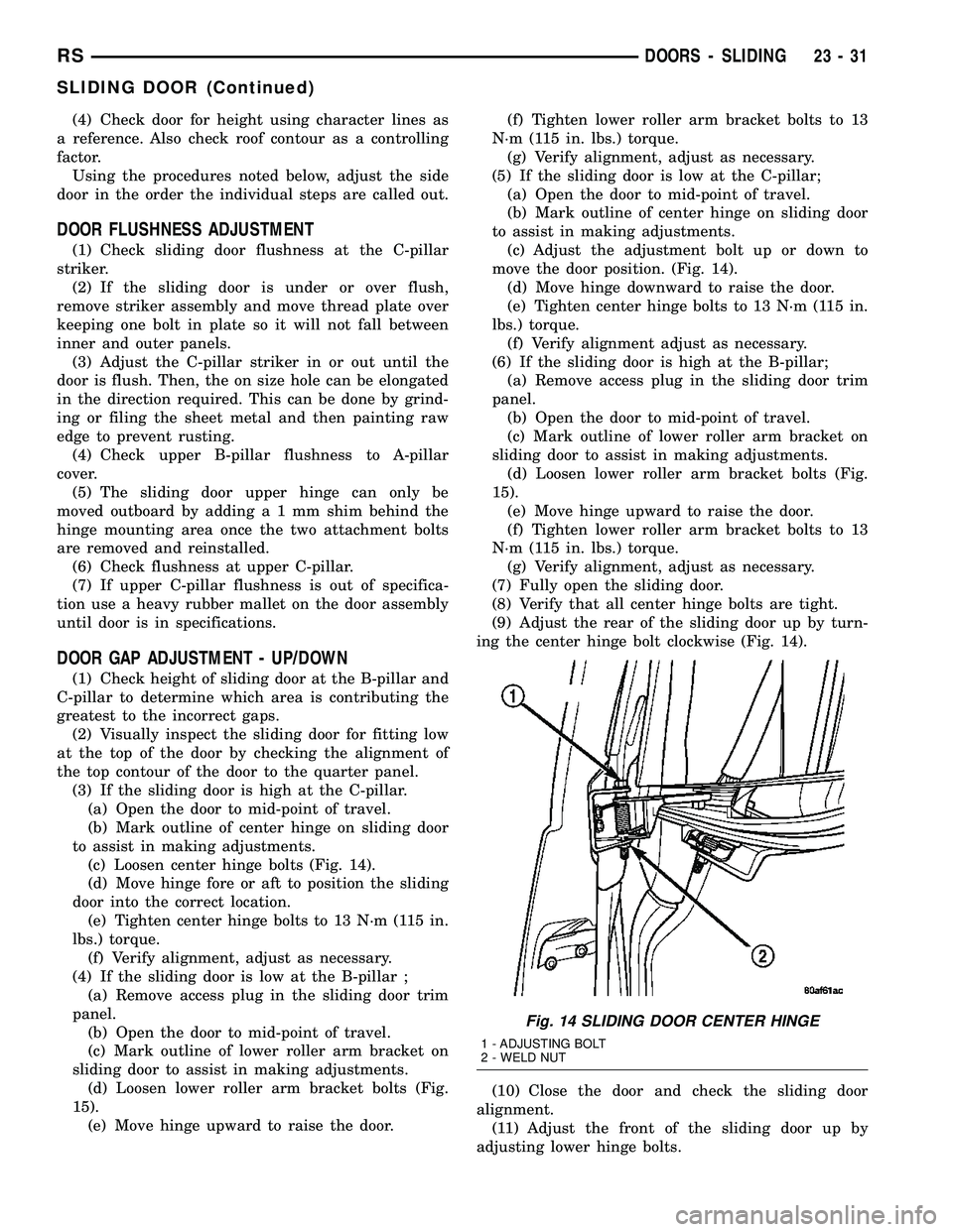
(c) Loosen center hinge bolts (Fig. 14).
(d) Move hinge fore or aft to position the sliding
door into the correct location.
(e) Tighten center hinge bolts to 13 N´m (115 in.
lbs.) torque.
(f) Verify alignment, adjust as necessary.
(4) If the sliding door is low at the B-pillar ;
(a) Remove access plug in the sliding door trim
panel.
(b) Open the door to mid-point of travel.
(c) Mark outline of lower roller arm bracket on
sliding door to assist in making adjustments.
(d) Loosen lower roller arm bracket bolts (Fig.
15).
(e) Move hinge upward to raise the door.(f) Tighten lower roller arm bracket bolts to 13
N´m (115 in. lbs.) torque.
(g) Verify alignment, adjust as necessary.
(5) If the sliding door is low at the C-pillar;
(a) Open the door to mid-point of travel.
(b) Mark outline of center hinge on sliding door
to assist in making adjustments.
(c) Adjust the adjustment bolt up or down to
move the door position. (Fig. 14).
(d) Move hinge downward to raise the door.
(e) Tighten center hinge bolts to 13 N´m (115 in.
lbs.) torque.
(f) Verify alignment adjust as necessary.
(6) If the sliding door is high at the B-pillar;
(a) Remove access plug in the sliding door trim
panel.
(b) Open the door to mid-point of travel.
(c) Mark outline of lower roller arm bracket on
sliding door to assist in making adjustments.
(d) Loosen lower roller arm bracket bolts (Fig.
15).
(e) Move hinge upward to raise the door.
(f) Tighten lower roller arm bracket bolts to 13
N´m (115 in. lbs.) torque.
(g) Verify alignment, adjust as necessary.
(7) Fully open the sliding door.
(8) Verify that all center hinge bolts are tight.
(9) Adjust the rear of the sliding door up by turn-
ing the center hinge bolt clockwise (Fig. 14).
(10) Close the door and check the sliding door
alignment.
(11) Adjust the front of the sliding door up by
adjusting lower hinge bolts.
Fig. 14 SLIDING DOOR CENTER HINGE
1 - ADJUSTING BOLT
2 - WELD NUT
RSDOORS - SLIDING23-31
SLIDING DOOR (Continued)
Page 1811 of 2339

(12) Open door half way and remove lower hinge
bolt access plug.
(13) Loosen bolts as necessary to move the front of
door up or down.
(14) Check the upper hinge for possible bind,
adjust as necessary.
(15) Close the door and check the sliding door
alignment.
(16) Fully open door and apply thread lock nut
onto the center hinge bolt. Tighten nut until till it
butts up against the welded nut on the center hinge.
Tighten nut to 13 N´m (115 in. lbs.) torque. It may be
necessary to hold the center hinge bolt to prevent it
from turning while tightening nut.
(17) Verify alignment, adjust as necessary.
DOOR GAP ADJUSTMENT - FORE/AFT
(1) Check C-pillar and B-pillar for door to aperture
gaps (5 mm + 1 mm), and door to door gap (5 mm +
1 mm).
(2) If adjust gaps require adjustment, loosen cen-
ter hinge screws as necessary to move center hinge
forward or rearward.
(3) Moving center hinge rearward increases the
gap at C-pillar and decreases gap at B-pillar. Moving
center hinge forward decreases gap at the C-pillar
and increases gap at the B-pillar
(4) Move center hinge as necessary, and tighten
screws.
(5) Close the door and check the sliding door align-
ment.
(6) Verify door alignment, adjust as necessary.
(7) Tighten center hinge screws to 13 N´m (115 in.
lbs.) torque.
DOOR SEAL COMPRESSION
(1) First check Gap & Flush (Refer to 23 - BODY/
BODY STRUCTURE/GAP AND FLUSH - SPECIFI-
CATIONS). Check seal compression near the middle
of the door even with the latch assembly. Using a
piece of paper, place it across door seal and close
door. Pull paper out of door opening. If paper tears
setting is to tight, if paper slides thought to easily
the compression is insufficient and needs to be
adjusted.
(2) Adjust seal compression at the top of the B-pil-
lar seal;
(a) Open door to mid-point of travel.
(b) Mark outline of upper roller arm on door to
assist in making adjustments.
(c) Loosen bolts attaching upper roller arm to
door (Fig. 16).
(d) Decrease the length of the upper roller arm
to increase seal compression.
(e) Increase the length of the upper roller arm to
decrease seal compression.
(f) Tighten all upper roller arm bolts to 13 N´m
(115 in. lbs.) torque.
(g) Verify door alignment, adjust as necessary.
(3) Adjust seal compression at the bottom of B-pil-
lar seal.
(a) Open door to mid-point of travel.
(b) Mark outline of lower roller arm on lower
roller arm bracket to assist in making adjustments
(Fig. 17).
(c) Loosen bolts holding lower roller arm to
lower roller arm bracket.
(d) Pivot lower roller arm toward center of vehi-
cle to decrease seal compression.
Fig. 15 SLIDING DOOR LOWER ROLLER ARM
1 - LOWER ROLLER ARM BRACKET
2 - BOLTS
3 - SLIDING DOOR
Fig. 16 Sliding Door Upper Roller Arm
1 - UPPER STOP PLATE
2 - SLIDING DOOR
3 - UPPER SLIDING DOOR HINGE
23 - 32 DOORS - SLIDINGRS
SLIDING DOOR (Continued)