LUG NUT CHRYSLER VOYAGER 2005 Owner's Guide
[x] Cancel search | Manufacturer: CHRYSLER, Model Year: 2005, Model line: VOYAGER, Model: CHRYSLER VOYAGER 2005Pages: 2339, PDF Size: 59.69 MB
Page 1261 of 2339

CONDITION POSSIBLE CAUSES CORRECTION
OIL CONSUMPTION OR SPARK
PLUGS FOULED1. PCV system malfunction. 1. Check system and repair as
necessary. (Refer to 25 -
EMISSIONS CONTROL/
EVAPORATIVE EMISSIONS/PCV
VALVE - DIAGNOSIS AND
TESTING)
2. Worn, scuffed or broken rings. 2. Hone cylinder bores. Install new
rings.
3. Carbon in oil ring slots. 3. Install new rings.
4. Rings fitted too tightly in grooves. 4. Remove rings and check
grooves. If groove is not proper
width, replace piston.
5. Worn valve guide(s). 5. Replace cylinder head assembly.
6. Valve stem seal(s) worn or
damaged.6. Replace seal(s).
DIAGNOSIS AND TESTING - ENGINE OIL LEAK
INSPECTION
Begin with a thorough visual inspection of the
engine, particularly at the area of the suspected leak.
If an oil leak source is not readily identifiable, the
following steps should be followed:
(1) Do not clean or degrease the engine at this
time because some solvents may cause rubber to
swell, temporarily stopping the leak.
(2) Add an oil soluble dye (use as recommended by
manufacturer). Start the engine and let idle for
approximately 15 minutes. Check the oil dipstick to
make sure the dye is thoroughly mixed as indicated
with a bright yellow color under a black light.
(3) Using a black light, inspect the entire engine
for fluorescent dye, particularly at the suspected area
of oil leak. If the oil leak is found and identified,
repair as necessary.
(4) If dye is not observed, drive the vehicle at var-
ious speeds for approximately 24 km (15 miles), and
repeat inspection.
(5)If the oil leak source is not positively
identified at this time, proceed with the air leak
detection test method as follows:
²Disconnect the fresh air hose (make-up air) at
the cylinder head cover and plug or cap the outlet on
the cover.
²Remove the PCV valve hose from the cylinder
head cover. Cap or plug the PCV valve outlet on the
cover.
²Attach an air hose with pressure gauge and reg-
ulator to the dipstick tube.
CAUTION: Do not subject the engine assembly to
more than 20.6 kpa (3 PSI) of test pressure.²Gradually apply air pressure from 1 psi to 2.5
psi maximum while applying soapy water at the sus-
pected source. Adjust the regulator to the suitable
test pressure that provides the best bubbles which
will pinpoint the leak source. If the oil leak is
detected and identified, repair per service manual
procedures.
²If the leakage occurs at the crankshaft rear oil
seal area, refer to the section, Inspection for Rear
Seal Area Leak.
(6) If no leaks are detected, turn off the air supply.
Remove the air hose, all plugs, and caps. Install the
PCV valve and fresh air hose (make-up air). Proceed
to next step.
(7) Clean the oil off the suspect oil leak area using
a suitable solvent. Drive the vehicle at various
speeds approximately 24 km (15 miles). Inspect the
engine for signs of an oil leak by using a black light.
NOTE: If oil leakage is observed at the dipstick tube
to block location; remove the tube, clean and reseal
using MoparTStud & Bearing Mount (press fit tube
applications only), and for O-ring style tubes,
remove tube and replace the O-ring seal.
INSPECTION FOR REAR SEAL AREA LEAKS
Since it is sometimes difficult to determine the
source of an oil leak in the rear seal area of the
engine, a more involved inspection is necessary. The
following steps should be followed to help pinpoint
the source of the leak.
If the leakage occurs at the crankshaft rear oil seal
area:
(1) Disconnect the battery.
(2) Raise the vehicle.
9 - 84 ENGINE 3.3/3.8LRS
ENGINE 3.3/3.8L (Continued)
Page 1266 of 2339

(13) Disconnect the EGR transducer electrical con-
nector (if equipped).
(14) Disconnect the vacuum hoses from throttle
body.
(15) Disconnect the brake booster and speed con-
trol vacuum hoses.
(16) Disengage wire harness clip from the right
side engine mount.
(17) Remove the power steering reservoir from
mounting position and set aside.Do notdisconnect
hose.
(18) Disconnect ground strap from rear of cylinder
head.
(19) Disconnect engine coolant temperature (ECT)
sensor and ignition coil electrical connectors.
(20) Disconnect the fuel injector electrical harness
connector and disengage clip from support bracket.
(21) Disconnect camshaft and crankshaft position
sensor electrical connectors.
(22) Evacuate air conditioning system. Refer to 24
- HEATING & AIR CONDITIONING.
(23) Disconnect A/C compressor electrical connec-
tor.
(24) Disconnect the A/C lines from compressor.
Cover and seal all openings of hoses and compressor.
(25) Remove the radiator upper hose.
(26) Disengage electrical harness clip at transaxle
dipstick tube.
(27) Remove transaxle dipstick tube. Seal opening
using a suitable plug.
NOTE: When the transaxle cooler lines are removed
from the rolled-groove type fittings at the transaxle,
damage to the inner wall of the hose will occur. To
prevent prevent potential leakage, the cooler hoses
must be cut off flush at the transaxle fitting, and a
service cooler hose splice kit must be installed
upon reassembly.
(28) Using a blade or suitable hose cutter, cut
transaxle oil cooler lines off flush with fittings. Plug
cooler lines and fittings to prevent debris from enter-
ing transaxle or cooler circuit. A service splice kit will
be installed upon reassembly.
(29) Disconnect transaxle shift linkage and electri-
cal connectors.
(30) Raise vehicle on hoist and drain the engine
oil.
(31) Remove the axle shafts. (Refer to 3 - DIFFER-
ENTIAL & DRIVELINE/HALF SHAFT - REMOVAL)
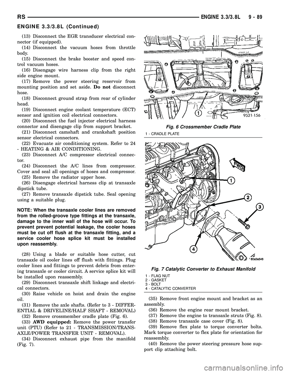
(32) Remove crossmember cradle plate (Fig. 6).
(33)AWD equipped:Remove the power transfer
unit (PTU) (Refer to 21 - TRANSMISSION/TRANS-
AXLE/POWER TRANSFER UNIT - REMOVAL).
(34) Disconnect exhaust pipe from the manifold
(Fig. 7).(35) Remove front engine mount and bracket as an
assembly.
(36) Remove the engine rear mount bracket.
(37) Remove the engine to transaxle struts (Fig. 8).
(38) Remove transaxle case cover (Fig. 8).
(39) Remove flex plate to torque converter bolts.
Mark torque converter to flex plate for orientation for
reassembly.
(40) Remove the power steering pressure hose sup-
port clip attaching bolt.
Fig. 6 Crossmember Cradle Plate
1 - CRADLE PLATE
Fig. 7 Catalytic Converter to Exhaust Manifold
1 - FLAG NUT
2 - GASKET
3 - BOLT
4 - CATALYTIC CONVERTER
RSENGINE 3.3/3.8L9-89
ENGINE 3.3/3.8L (Continued)
Page 1292 of 2339

REMOVAL
(1) Remove the valve springs. (Refer to 9 -
ENGINE/CYLINDER HEAD/VALVE SPRINGS -
REMOVAL)
(2) Remove the valve stem seal (Fig. 44).
INSTALLATION
(1) Install the valve stem seal squarely over the
valve guide, using the valve stem as a guide (Fig.
44). Do not force the seal against top of the valve
guide.
(2) Install the valve spring. (Refer to 9 - ENGINE/
CYLINDER HEAD/VALVE SPRINGS - INSTALLA-
TION)
ENGINE BLOCK
DESCRIPTION
The cylinder block is made of cast iron and is a
deep skirt design.
STANDARD PROCEDURE - CYLINDER BORE
HONING
(1) Used carefully, the cylinder bore resizing hone,
recommended tool C-823 or equivalent, equipped
with 220 grit stones, is the best tool for this honing
procedure. In addition to deglazing, it will reduce
taper and out-of-round as well as removing light
scuffing, scoring or scratches. Usually a few strokes
will clean up a bore and maintain the required lim-
its.
(2) Deglazing of the cylinder walls may be done
using a cylinder surfacing hone, recommended tool
C-3501 or equivalent, equipped with 280 grit stones,
if the cylinder bore is straight and round. 20±60
strokes depending on the bore condition, will be suf-
ficient to provide a satisfactory surface. Use a light
honing oil.Do not use engine or transmission oil,
mineral spirits or kerosene.Inspect cylinder walls
after each 20 strokes.
(3) Honing should be done by moving the hone up
and down fast enough to get a cross-hatch pattern.
When hone marksintersectat 40-60 degrees, the
cross hatch angle is most satisfactory for proper seat-
ing of rings (Fig. 45).
(4) A controlled hone motor speed between
200±300 RPM is necessary to obtain the proper cross-
hatch angle. The number of up and down strokes per
minute can be regulated to get the desired 40±60
degree angle. Faster up and down strokes increase
the cross-hatch angle.
(5) After honing, it is necessary that the block be
cleaned again to remove all traces of abrasive.CAUTION: Ensure all abrasives are removed from
engine parts after honing. It is recommended that a
solution of soap and hot water be used with a
brush and the parts then thoroughly dried. The bore
can be considered clean when it can be wiped
clean with a white cloth and cloth remains clean.
Oil the bores after cleaning to prevent rusting.
CLEANING
Clean cylinder block thoroughly using a suitable
cleaning solvent.
INSPECTION
ENGINE BLOCK
(1) Clean cylinder block thoroughly and check all
core hole plugs for evidence of leaking.
(2) If new core plugs are to be installed, (Refer to 9
- ENGINE - STANDARD PROCEDURE - ENGINE
CORE AND OIL GALLERY PLUGS).
(3) Examine block and cylinder bores for cracks or
fractures.
(4) Check block deck surfaces for flatness. Deck
surface must be within service limit of 0.1 mm (0.004
in.).
CYLINDER BORE
NOTE: The cylinder bores should be measured at
normal room temperature, 21ÉC (70ÉF).
The cylinder walls should be checked for out-of-
round and taper with Tool C119 or equivalent (Fig.
Fig. 45 Cylinder Bore Cross-Hatch Pattern
1 - CROSS-HATCH PATTERN
2 - 40ɱ60É
RSENGINE 3.3/3.8L9 - 115
VALVE STEM SEALS (Continued)
Page 1317 of 2339

(11) Start engine and inspect for leaks.
(12) Stop engine and inspect oil level.
NOTE: Care should be exercised when disposing
used engine oil after it has been drained from a
vehicle engine. Refer to the WARNING listed above.
STANDARD PROCEDURE - ENGINE OIL LEVEL
CHECK
The best time to check engine oil level is after it
has sat overnight, or if the engine has been running,
allow the engine to be shut off for at least 5 minutes
before checking oil level.
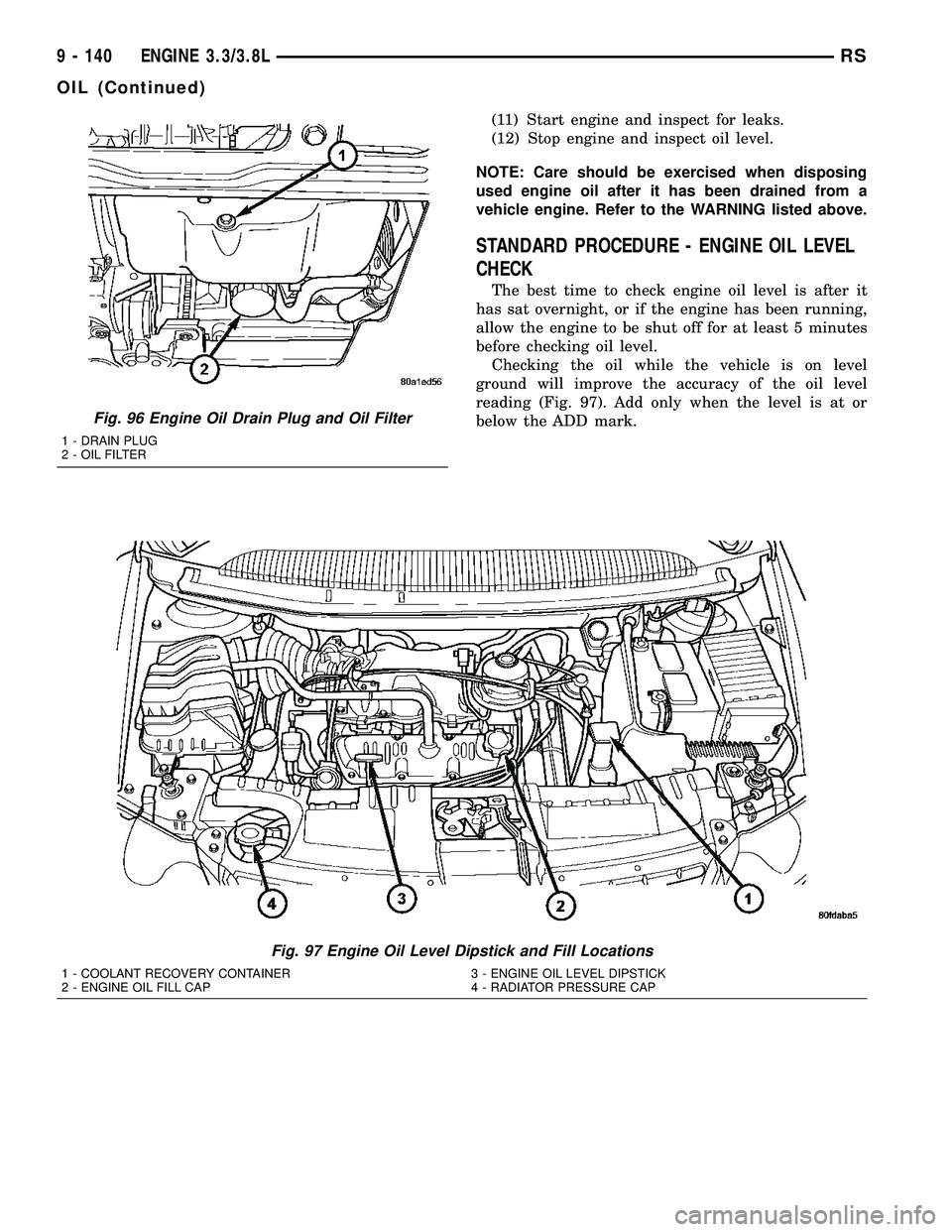
Checking the oil while the vehicle is on level
ground will improve the accuracy of the oil level
reading (Fig. 97). Add only when the level is at or
below the ADD mark.
Fig. 97 Engine Oil Level Dipstick and Fill Locations
1 - COOLANT RECOVERY CONTAINER 3 - ENGINE OIL LEVEL DIPSTICK
2 - ENGINE OIL FILL CAP 4 - RADIATOR PRESSURE CAP
Fig. 96 Engine Oil Drain Plug and Oil Filter
1 - DRAIN PLUG
2 - OIL FILTER
9 - 140 ENGINE 3.3/3.8LRS
OIL (Continued)
Page 1320 of 2339

INSPECTION
(1) Inspect oil drain plug and plug hole for
stripped or damaged threads and repair as necessary.
Install a new drain plug gasket. Tighten to 27 N´m
(20 ft. lbs.).
(2) Inspect oil pan mounting flange for bends or
distortion. Straighten flange if necessary.
(3) Inspect condition of oil screen and pick-up tube.
INSTALLATION
(1) Clean sealing surfaces and apply a 1/8 inch
bead of MopartEngine RTV GEN II at the parting
line of the chain case cover and the rear seal retainer
(Fig. 103).
(2) Position a new pan gasket on oil pan (Fig. 102).
(3) Install oil pan and tighten fasteners to 12 N´m
(105 in. lbs.) (Fig. 102).
(4) Install cover to transaxle case (Fig. 101).
(5) Install the strut bolt to transaxle housing (Fig.
101). Tighten all bending brace bolts.
(6) Install the drive belt splash shield.
(7) Lower vehicle and install oil dipstick.
(8) Connect negative cable to battery.
(9) Fill crankcase with oil to proper level.
OIL PRESSURE RELIEF VALVE
REMOVAL
(1) Remove oil pan (Refer to 9 - ENGINE/LUBRI-
CATION/OIL PAN - REMOVAL).
(2) Drill a 3.175 mm (1/8 in.) hole in the center of
the retainer cap (Fig. 104). Insert a self-threading
sheet metal screw into the cap.
(3) Using suitable pliers, remove cap and discard.
(4) Remove spring and relief valve (Fig. 104).
Fig. 102 OIL PAN
1 - GASKET
2 - BOLT
3 - OIL PAN
4 - NUT
Fig. 103 Oil Pan Sealing
1 - SEALER LOCATIONS
Fig. 104 Oil Pressure Relief Valve
1 - RELIEF VALVE
2 - SPRING
3 - RETAINER CAP
RSENGINE 3.3/3.8L9 - 143
OIL PAN (Continued)
Page 1328 of 2339

WARNING: INTAKE MANIFOLD GASKET IS MADE
OF VERY THIN METAL AND MAY CAUSE PER-
SONAL INJURY, HANDLE WITH CARE.
(12) Remove intake manifold seal retainers screws
(Fig. 122). Remove intake manifold gasket.
(13) Inspect and clean manifold. (Refer to 9 -
ENGINE/MANIFOLDS/INTAKE MANIFOLD -
INSPECTION) (Refer to 9 - ENGINE/MANIFOLDS/
INTAKE MANIFOLD - CLEANING)
CLEANING
(1) Discard gasket(s).
(2) Clean all sealing surfaces.
INSPECTION
Check for:
²Damage and cracks of each section.
²Clogged water passages in end cross-overs (if
equipped).²Check for cylinder head mounting surface distor-
tion using a straightedge and thickness gauge. (Refer
to 9 - ENGINE/CYLINDER HEAD - INSPECTION)
INSTALLATION - LOWER INTAKE MANIFOLD
(1) Place a bead (approximately 1/4 in. diameter)
of MopartEngine RTV GEN II onto each of thefour
manifold to cylinder head gasket corners (Fig. 123).
(2) Carefully install the new intake manifold gas-
ket (Fig. 122). Tighten end seal retainer screws to 12
N´m (105 in. lbs.).
(3) Install lower intake manifold (Fig. 122). Install
the bolts and torque to 1 N´m (10 in. lbs.). Then
torque bolts to 22 N´m (200 in. lbs.) in sequence
shown in (Fig. 124). Then torque again to 22 N´m
(200 in. lbs.). After intake manifold is in place,
inspect to make sure seals are in place.
(4) Install the fuel injectors and rail assembly.
(Refer to 14 - FUEL SYSTEM/FUEL DELIVERY/
FUEL RAIL - INSTALLATION)
(5) Connect fuel injector electrical harness.
(6) Connect the engine coolant temperature sensor
(Fig. 121).
(7) Connect the heater supply (Fig. 121) and radi-
ator upper hoses to manifold.
(8) Connect the fuel line. (Refer to 14 - FUEL SYS-
TEM/FUEL DELIVERY/QUICK CONNECT FIT-
TING - STANDARD PROCEDURE)
Fig. 120 FUEL RAIL AND IGNITION COIL &
BRACKET
1 - FUEL RAIL
2 - BOLT - FUEL RAIL
3 - NUT - IGNITION COIL
4 - BOLT - IGNITION COIL
5 - IGNITION COIL
6 - BRACKET - IGNITION COIL
7 - STUD - IGNITION COIL
8 - SEPARATOR - SPARK PLUG CABLE
9 - BRACKET - SPARK PLUG CABLE SEPARATOR
10 - BOLT - SEPARATOR BRACKET
11 - BRACKET - SPARK PLUG CABLE SEPARATOR
Fig. 121 ECT SENSOR & HEATER SUPPLY
1 - ENGINE COOLANT TEMPERATURE SENSOR
2 - CONNECTOR - ENGINE COOLANT SENSOR
3 - FITTING - HEATER SUPPLY
RSENGINE 3.3/3.8L9 - 151
INTAKE MANIFOLD - LOWER (Continued)
Page 1329 of 2339

(9) Install the upper intake manifold. (Refer to 9 -
ENGINE/MANIFOLDS/INTAKE MANIFOLD -
INSTALLATION)
(10) Connect negative battery cable.(11) Fill the cooling system. (Refer to 7 - COOL-
ING - STANDARD PROCEDURE)
EXHAUST MANIFOLD - RIGHT
REMOVAL
(1) Disconnect battery negative cable.
(2) Remove the wiper module. (Refer to 8 - ELEC-
TRICAL/WIPERS/WASHERS/WIPER MODULE -
REMOVAL)
(3) Disconnect spark plug wires.
(4) Remove bolts fastening crossover pipe to
exhaust manifold (Fig. 125).
(5) Disconnect and remove the upstream oxygen
sensor (Fig. 128).
Fig. 122 INTAKE MANIFOLD - LOWER
1 - INTAKE MANIFOLD - LOWER
2 - BOLT - GASKET END SEAL RETAINER
3 - GASKET
4 - BOLT - LOWER INTAKE MANIFOLD
Fig. 123 Intake Manifold Gasket Sealing
1 - SEALER LOCATIONS
Fig. 124 LOWER MANIFOLD TIGHTENING
SEQUENCE
Fig. 125 CROSS-OVER PIPE
1 - CROSS-OVER PIPE
2 - BOLT
3 - GASKET
4 - FLAG NUT
9 - 152 ENGINE 3.3/3.8LRS
INTAKE MANIFOLD - LOWER (Continued)
Page 1331 of 2339

NOTE: Inspect crossover pipe fasteners for damage
from heat and corrosion. The cross-over bolts are
made of a special stainless steel alloy. If replace-
ment is required, OEM bolts are highly recom-
mended.
(3) Install the remaining manifold attaching bolts.
Tighten all bolts to 23 N´m (200 in. lbs.).
(4) Position the power steering pump support strut
and install upper bolt (Fig. 126).
(5) Install heat shield and attaching screws (Fig.
128).
(6) Install and connect upstream oxygen sensor
(Fig. 128).
(7) Raise the vehicle.
(8) Attach catalytic converter pipe to exhaust man-
ifold using new gasket and tighten bolts to 37 N´m
(27 ft. lbs.) (Fig. 127).
(9) Connect downstream oxygen sensor connector.
(10) Tighten the power steering pump support
strut lower bolt (Fig. 126).
(11) Install the belt splash shield and lower the
vehicle.
(12) Install the wiper module. (Refer to 8 - ELEC-
TRICAL/WIPERS/WASHERS/WIPER MODULE -
INSTALLATION)
(13) Connect battery negative cable.
EXHAUST MANIFOLD - LEFT
REMOVAL
(1) Disconnect battery negative cable.
(2) Remove bolts attaching crossover pipe to
exhaust manifold (Fig. 130).
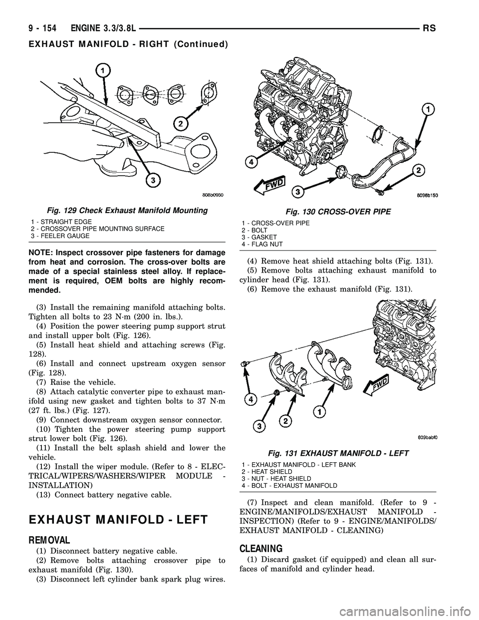
(3) Disconnect left cylinder bank spark plug wires.(4) Remove heat shield attaching bolts (Fig. 131).
(5) Remove bolts attaching exhaust manifold to
cylinder head (Fig. 131).
(6) Remove the exhaust manifold (Fig. 131).
(7) Inspect and clean manifold. (Refer to 9 -
ENGINE/MANIFOLDS/EXHAUST MANIFOLD -
INSPECTION) (Refer to 9 - ENGINE/MANIFOLDS/
EXHAUST MANIFOLD - CLEANING)CLEANING
(1) Discard gasket (if equipped) and clean all sur-
faces of manifold and cylinder head.
Fig. 129 Check Exhaust Manifold Mounting
1 - STRAIGHT EDGE
2 - CROSSOVER PIPE MOUNTING SURFACE
3 - FEELER GAUGE
Fig. 130 CROSS-OVER PIPE
1 - CROSS-OVER PIPE
2 - BOLT
3 - GASKET
4 - FLAG NUT
Fig. 131 EXHAUST MANIFOLD - LEFT
1 - EXHAUST MANIFOLD - LEFT BANK
2 - HEAT SHIELD
3 - NUT - HEAT SHIELD
4 - BOLT - EXHAUST MANIFOLD
9 - 154 ENGINE 3.3/3.8LRS
EXHAUST MANIFOLD - RIGHT (Continued)
Page 1332 of 2339

INSPECTION
Inspect exhaust manifolds for damage or cracks
and check distortion of the cylinder head mounting
surface and exhaust crossover mounting surface with
a straightedge and thickness gauge (Fig. 132).
Manifold surface flatness limits should not exceed
1.0 mm (0.039 in.).
INSTALLATION
(1) Position exhaust manifold on cylinder head
(Fig. 131). Install bolts to center runner (cylinder #4)
and initial tighten to 2.8 N´m (25 in. lbs.).
(2) Using a new gasket, attach crossover pipe to
exhaust manifold and tighten bolts to 41 N´m (30 ft.
lbs.) (Fig. 130).
NOTE: Inspect crossover pipe fasteners for damage
from heat and corrosion. The cross-over bolts are
made of a special stainless steel alloy. If replace-
ment is required, OEM bolts are highly recom-
mended.
(3) Position heat shield on manifold (Fig. 131).
(4) Install the remaining manifold attaching bolts.
Tighten all bolts to 23 N´m (200 in. lbs.).
(5) Install and tighten heat shield attaching nut to
12 N´m (105 in. lbs.) (Fig. 131).
(6) Connect battery negative cable.
VALVE TIMING
STANDARD PROCEDURE
STANDARD PROCEDURE - VALVE TIMING
VERIFICATION
(1) Remove front cylinder head cover and all 6
spark plugs.
(2) Rotate engine until the #2 piston is at TDC of
the compression stroke.
(3) Install a degree wheel on the crankshaft pulley.
(4) With proper adaptor, install a dial indicator
into #2 spark plug hole. Using the indicator find TDC
on the compression stroke.
(5) Position the degree wheel to zero.
(6) Remove dial indicator from spark plug hole.
(7) Place a 5.08 mm (0.200 in.) spacer between the
valve stem tip of #2 intake valve and rocker arm pad.
Allow tappet to bleed down to give a solid tappet
effect.
(8) Install a dial indicator so plunger contacts the
#2 intake valve spring retainer as nearly perpendic-
ular as possible. Zero the indicator.
(9) Rotate the engine clockwise until the intake
valve has lifted .254 mm (0.010 in.).
CAUTION: Do not turn crankshaft any further clock-
wise as intake valve might bottom and result in
serious damage.
(10) Degree wheel should read 6 degrees BTDC to
6 degrees ATDC.
STANDARD PROCEDURE - MEASURING
TIMING CHAIN WEAR
NOTE: This procedure must be performed with the
timing chain cover removed (Refer to 9 - ENGINE/
VALVE TIMING/TIMING CHAIN COVER - REMOVAL).
(1) Position a scale next to timing chain so that
any movement of chain may be measured (Fig. 133).
(2) Position a torque wrench and socket on the
camshaft sprocket attaching bolt. Apply force in the
direction of crankshaft rotation to take up slack to
the following torque:
²41 N´m (30 ft. lb.) with cylinder heads installed
²20 N´m (15 ft. lb.) with cylinder heads removed
NOTE: With torque applied to the camshaft
sprocket bolt, crankshaft should not be permitted to
move. It may be necessary to block crankshaft to
prevent rotation.
(3) Holding a measuring scale along edge of chain
links (Fig. 133).
Fig. 132 Check Exhaust Manifold Mounting
1 - STRAIGHT EDGE
2 - CROSSOVER PIPE MOUNTING SURFACE
3 - FEELER GAUGE
RSENGINE 3.3/3.8L9 - 155
EXHAUST MANIFOLD - LEFT (Continued)
Page 1342 of 2339

Catalyst operation is dependent on its ability to
store and release the oxygen needed to complete the
emissions-reducing chemical reactions. As a catalyst
deteriorates, its ability to store oxygen is reduced.
Since the catalyst's ability to store oxygen is some-
what related to proper operation, oxygen storage can
be used as an indicator of catalyst performance.
Refer to the appropriate Diagnostic Information for
diagnosis of a catalyst related Diagnostic Trouble
Code (DTC).
The combustion reaction caused by the catalyst
releases additional heat in the exhaust system, caus-
ing temperature increases in the area of the reactor
under severe operating conditions. Such conditions
can exist when the engine misfires or otherwise does
not operate at peak efficiency.Do notremove spark
plug wires from plugs or by any other means short
out cylinders. Failure of the catalytic converter can
occur due to temperature increases caused by
unburned fuel passing through the converter. This
deterioration of the catalyst core can result in exces-
sively high emission levels, noise complaints, and
exhaust restrictions.
Unleaded gasoline must be used to avoid ruining
the catalyst core. Do not allow engine to operate
above 1200 RPM in neutral for extended periods over
5 minutes. This condition may result in excessive
exhaust system/floor pan temperatures because of no
air movement under the vehicle.
The flex joint allows flexing as the engine moves,
preventing breakage that could occur from the back-
and-forth motion of a transverse mounted engine.
CAUTION: Due to exterior physical similarities of
some catalytic converters with pipe assemblies,
extreme care should be taken with replacement
parts. There are internal converter differences
required in some parts of the country (particularly
vehicles built for States with strict emission
requirements) and between model years.
REMOVAL
(1) Loosen clamp and disconnect the muffler/reso-
nator assembly from catalytic converter pipe.
(2) Disconnect downstream oxygen sensor electri-
cal connector (Fig. 4). For removal of downstream
oxygen sensor, (Refer to 14 - FUEL SYSTEM/FUEL
INJECTION/O2 SENSOR - REMOVAL).
(3) Remove catalytic converter to exhaust manifold
attaching fasteners (Fig. 5).
(4) Remove catalytic converter and gasket (Fig. 5).
Fig. 4 Downstream Oxygen Sensor
1 - OXYGEN SENSOR CONNECTOR
2 - CATALYTIC CONVERTER
3 - DOWNSTREAM OXYGEN SENSOR
4 - ENGINE HARNESS CONNECTOR
Fig. 5 Catalytic Converter to Exhaust Manifold
1 - FLAG NUT
2 - GASKET
3 - BOLT
4 - CATALYTIC CONVERTER
RSEXHAUST SYSTEM11-5
CATALYTIC CONVERTER (Continued)