torque CHRYSLER VOYAGER 2005 Service Manual
[x] Cancel search | Manufacturer: CHRYSLER, Model Year: 2005, Model line: VOYAGER, Model: CHRYSLER VOYAGER 2005Pages: 2339, PDF Size: 59.69 MB
Page 1615 of 2339

DIAGNOSIS AND TESTING - TORQUE
CONVERTER HOUSING FLUID LEAKAGE
When diagnosing converter housing fluid leaks,
three actions must be taken before repair:
(1) Verify proper transmission fluid level.
(2) Verify that the leak originates from the con-
verter housing area and is transmission fluid.
(3) Determine the true source of the leak.
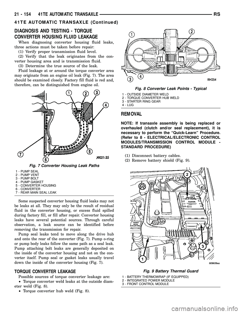
Fluid leakage at or around the torque converter area
may originate from an engine oil leak (Fig. 7). The area
should be examined closely. Factory fill fluid is red and,
therefore, can be distinguished from engine oil.
Some suspected converter housing fluid leaks may not
be leaks at all. They may only be the result of residual
fluid in the converter housing, or excess fluid spilled
during factory fill, or fill after repair. Converter housing
leaks have several potential sources. Through careful
observation, a leak source can be identified before
removing the transmission for repair.
Pump seal leaks tend to move along the drive hub
and onto the rear of the converter (Fig. 7). Pump o-ring
or pump body leaks follow the same path as a seal leak.
Pump attaching bolt leaks are generally deposited on
the inside of the converter housing and not on the con-
verter itself. Pump seal or gasket leaks usually travel
down the inside of the converter housing (Fig. 7).
TORQUE CONVERTER LEAKAGE
Possible sources of torque converter leakage are:
²Torque converter weld leaks at the outside diam-
eter weld (Fig. 8).
²Torque converter hub weld (Fig. 8).
REMOVAL
NOTE: If transaxle assembly is being replaced or
overhauled (clutch and/or seal replacement), it is
necessary to perform the ªQuick-Learnº Procedure.
(Refer to 8 - ELECTRICAL/ELECTRONIC CONTROL
MODULES/TRANSMISSION CONTROL MODULE -
STANDARD PROCEDURE)
(1) Disconnect battery cables.
(2) Remove battery shield (Fig. 9).
Fig. 7 Converter Housing Leak Paths
1 - PUMP SEAL
2 - PUMP VENT
3 - PUMP BOLT
4 - PUMP GASKET
5 - CONVERTER HOUSING
6 - CONVERTER
7 - REAR MAIN SEAL LEAK
Fig. 8 Converter Leak Points - Typical
1 - OUTSIDE DIAMETER WELD
2 - TORQUE CONVERTER HUB WELD
3 - STARTER RING GEAR
4 - LUG
Fig. 9 Battery Thermal Guard
1 - BATTERY THERMOWRAP (IF EQUIPPED)
2 - INTEGRATED POWER MODULE
3 - FRONT CONTROL MODULE
21 - 154 41TE AUTOMATIC TRANSAXLERS
41TE AUTOMATIC TRANSAXLE (Continued)
Page 1617 of 2339

(11) Reposition leak detection pump harness and
hoses.
(12) Remove rear mount bracket-to-transaxle case
bolts (Fig. 13).
(13) Remove transaxle upper bellhousing-to-block
bolts.
(14) Raise vehicle on hoist.
(15) Remove transaxle oil pan and drain fluid into
suitable container.
(16) Remove front wheel/tire assemblies.
(17) Remove left and right halfshaft assemblies.
(Refer to 3 - DIFFERENTIAL & DRIVELINE/HALF
SHAFT - REMOVAL)
(18) AWD models: Remove power transfer unit.
(Refer to 21 - TRANSMISSION/TRANSAXLE/
POWER TRANSFER UNIT - REMOVAL)
(19) Remove rear mount bracket-to-transaxle case
lower (horizontal) bolt (Fig. 13).
(20) Remove front mount/bracket assembly.
(21) Remove starter motor.
(22) Remove lateral bending brace.
(23) Remove inspection cover.
(24) Remove torque converter-to-drive plate bolts.
(25) Support engine/transaxle assembly at engine
oil pan with screw jack and wood block.
(26) Partially remove left wheelhouse splash shield
to gain access to and remove upper mount thru-bolt
(Fig. 14).(27) Lower engine/transaxle assembly with screw
jack.
Fig. 13 Rear Mount Bracket - Typical
1 - BOLT - VERTICAL
2 - BRACKET - REAR MOUNT3 - BOLT - HORIZONTAL
Fig. 14 Left Mount-to-Bracket
1 - BOLT - BRACKET TO FRAME RAIL
2 - BOLT - MOUNT TO RAIL THROUGH
3 - BOLT - LEFT MOUNT TO TRANSAXLE
4 - TRANSAXLE
5 - MOUNT - LEFT
6 - BRACKET - LEFT MOUNT
21 - 156 41TE AUTOMATIC TRANSAXLERS
41TE AUTOMATIC TRANSAXLE (Continued)
Page 1636 of 2339

(2) Install low/reverse piston retainer gasket (Fig.
86). Make sure gasket holes line up with case.
(3) Install low/reverse piston retainer (Fig. 87).(4) Install low/reverse piston retainer-to-case bolts
(Fig. 88) and torque to 5 N´m (45 in. lbs.).
NOTE: The Low/Reverse Clutch Piston has bonded
seals which are not individually serviceable. Seal
replacement requires replacement of the piston
assembly.
(5) Install low/reverse clutch piston (Fig. 89).
Fig. 86 Install Piston Retainer Gasket
1 - GASKET HOLES MUST LINE UP
2 - LOW/REVERSE CLUTCH PISTON RETAINER GASKET
Fig. 87 Install Piston Retainer
1 - LOW/REVERSE CLUTCH PISTON RETAINER
2 - GASKET
Fig. 88 Install Piston Retainer Attaching Screws
1 - LOW/REVERSE CLUTCH PISTON RETAINER
2 - SCREWDRIVER
3 - TORX-LOC SCREWS
Fig. 89 Install Low/Reverse Clutch Piston
1 - LOW/REVERSE CLUTCH PISTON
2 - BONDED SEAL
3 - BONDED SEAL
RS41TE AUTOMATIC TRANSAXLE21 - 175
41TE AUTOMATIC TRANSAXLE (Continued)
Page 1639 of 2339

(12) Install rear carrier assembly to transaxle case
(Fig. 98).
(13) Install output gear bearing cone using Tool
5052 (Fig. 99).
(14)OUTPUT GEAR BEARING ADJUST-
MENT:
(a) With output gear removed, install a 4.50 mm
(0.177 in.) gauging shim (Fig. 101) on the rear car-
rier assembly hub, using grease to hold the shim in
place.
(b) Using Tool 6259, install output gear and
bearing assembly. Torque to 271 N´m (200 ft. lbs.).
(c) Measure bearing end play. Attach Tool L-4432
to the gear (Fig. 100).(d) Push and pull the gear while rotating back
and forth to ensure seating of bearing rollers.
(e) Using a dial indicator mounted to the trans-
axle case, measure output gear end play as shown
in (Fig. 100).
(f) Refer to the output gear bearing shim chart
for the required shim to obtain proper bearing set-
ting.
(g) Use Tool 6259 to remove the output gear
retaining bolt and washer. To remove the output
gear, use Tool L4407A.
(h) Remove the gauging shim and install the
proper shim determined by the chart. Use grease
to hold the shim in place.
Fig. 98 Install Rear Carrier Assembly
1 - REAR CARRIER ASSEMBLY
Fig. 99 Install Output Gear Bearing Cone
1 - ARBOR PRESS RAM
2 - HANDLE C-4171
3 - TOOL 5052
4 - OUTPUT GEAR
Fig. 100 Checking Output Gear Bearings End Play
1 - TOOL L-4432
2 - DIAL INDICATOR
3 - SPECIAL SCREWS TOOL 6260
4 - OUTPUT GEAR
Fig. 101 Output Gear and (Select) Shim
1 - REAR CARRIER ASSEMBLY
2 - SHIM (SELECT)
3 - OUTPUT GEAR
21 - 178 41TE AUTOMATIC TRANSAXLERS
41TE AUTOMATIC TRANSAXLE (Continued)
Page 1641 of 2339

(15) Install the output gear and bearing assembly
using Tool 6261 (Fig. 102).
(16) Install NEW output gear retaining bolt and
washer (Fig. 103). Using Tool 6259, torque output
gear retaining bolt to 271 N´m (200 ft. lbs.) (Fig.
104).(17) Using an inch pound torque wrench (Fig.
105), check output shaft turning torque.Output
shaft turning torque should be within 3-8 in.
lbs.If the turning torque is too high, install a 0.04
mm (0.0016 in.) thicker shim. If the turning torque is
too low, install a 0.04 mm (0.0016 in.) thinner shim.
Repeat until the proper turning torque of 3-8 in. lbs.
is obtained.
Fig. 102 Install Output Gear
1 - WRENCHES
2 - TOOL 6261 WITH STUD
3 - OUTPUT GEAR
Fig. 103 Output Gear Bolt and Washer
1 - OUTPUT GEAR
2 - BOLT
3 - CONED LOCK WASHER
Fig. 104 Tighten Output Gear to 271 N²m (200 ft.
lbs.)
1 - OUTPUT GEAR
2 - TORQUE WRENCH
3 - 200 FT. LBS.
4 - TOOL 6259
Fig. 105 Check Output Gear Bearings Turning
Torque
1 - INCH-POUND TORQUE WRENCH
2 - OUTPUT GEAR
21 - 180 41TE AUTOMATIC TRANSAXLERS
41TE AUTOMATIC TRANSAXLE (Continued)
Page 1642 of 2339

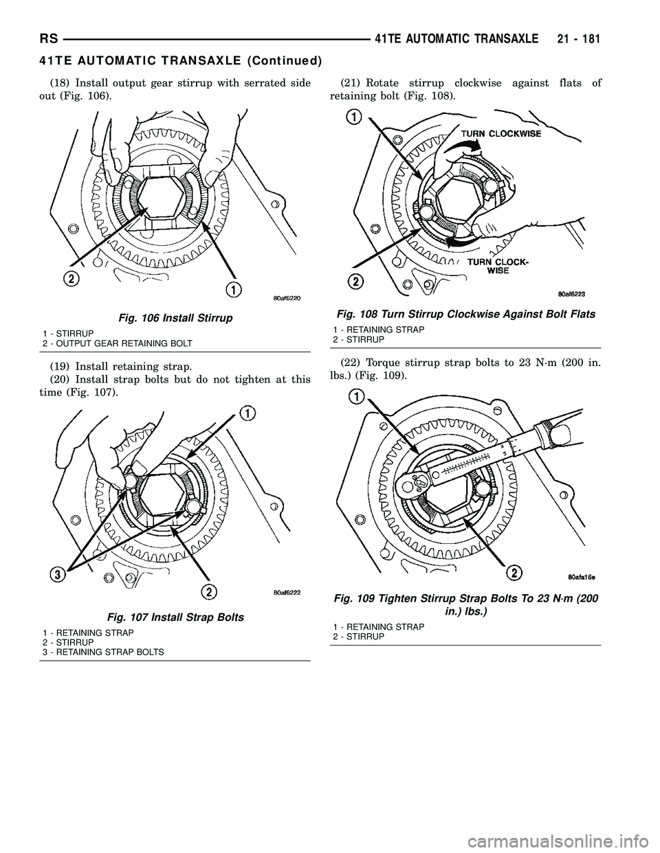
(18) Install output gear stirrup with serrated side
out (Fig. 106).
(19) Install retaining strap.
(20) Install strap bolts but do not tighten at this
time (Fig. 107).(21) Rotate stirrup clockwise against flats of
retaining bolt (Fig. 108).
(22) Torque stirrup strap bolts to 23 N´m (200 in.
lbs.) (Fig. 109).
Fig. 106 Install Stirrup
1 - STIRRUP
2 - OUTPUT GEAR RETAINING BOLT
Fig. 107 Install Strap Bolts
1 - RETAINING STRAP
2 - STIRRUP
3 - RETAINING STRAP BOLTS
Fig. 108 Turn Stirrup Clockwise Against Bolt Flats
1 - RETAINING STRAP
2 - STIRRUP
Fig. 109 Tighten Stirrup Strap Bolts To 23 N´m (200
in.) lbs.)
1 - RETAINING STRAP
2 - STIRRUP
RS41TE AUTOMATIC TRANSAXLE21 - 181
41TE AUTOMATIC TRANSAXLE (Continued)
Page 1647 of 2339

(32) Install the transfer shaft gear using Tool 6261
(Fig. 119).
CAUTION: Install a NEW retaining nut, as the origi-
nal nut MUST NOT be reused.
(33) Install the new retaining nut and washer.
(34) Using Tool 6259, torque transfer gear retain-
ing nut to 271 N´m (200 ft. lbs.) (Fig. 120).(35) Measure transfer shaft end play.Transfer
shaft end play should be within 0.05-0.10 mm
(0.002-0.004 in.).If the end play is too high, install a
0.04 mm (0.0016 in.) thicker shim. If the end play is
too low, install a 0.04 mm (0.0016 in.) thinner shim.
Repeat until 0.05-0.10 mm (0.002-0.004 in.) end play
is obtained.
(36) Install a bead of MopartATF RTV (MS-GF41)
to transfer gear cover (Fig. 121).
(37) Install transfer gear cover-to-case bolts and
torque to 20 N´m (175 in. lbs.) torque (Fig. 122).
Fig. 119 Install Transfer Shaft Gear
1 - WRENCHES
2 - SPECIAL TOOL 6261
3 - OUTPUT GEAR
4 - TRANSFER SHAFT GEAR
Fig. 120 Tighten Transfer Gear Nut to 271 N²m (200
ft. lbs.)
1 - TRANSFER SHAFT GEAR
2 - 200 FT. LBS.
3 - TORQUE WRENCH
4 - SPECIAL TOOL 6259
Fig. 121 Install Rear Cover
1 - REAR COVER
2 - 1/8 INCH BEAD OF MOPARTATF RTV (MS-GF41) AS SHOWN
Fig. 122 Install Rear Cover Bolts
1 - REAR COVER BOLTS
2 - REAR COVER
3 - USE SEALANT ON BOLTS
21 - 186 41TE AUTOMATIC TRANSAXLERS
41TE AUTOMATIC TRANSAXLE (Continued)
Page 1652 of 2339

(52)DETERMINING #4 THRUST PLATE
THICKNESS / INPUT SHAFT END PLAY:
(a) Select the thinnest #4 thrust plate thickness
and install to input clutch assembly (Fig. 139). Use
petrolatum to retain.
(b)
Install input clutch assembly into position and
verify that it is completely seated by viewing through
input speed sensor hole. If view through input speed
sensor hole is not as shown in (Fig. 140), the input
clutch assembly is not seated properly.
(c) Remove oil pump o-ring (Fig. 141).Be sure
to reinstall oil pump o-ring after selecting the
proper #4 thrust plate.
(d) Install pump and gasket to transmission.
Install and torque bolts.
(e) Set up input shaft for measurement with
Indicator Set C3339 and End Play Set 8266 as
shown in (Fig. 142).(f) Measure the input shaft end play with the
transaxle in the vertical position.Input shaft end
play must be within 0.005 to 0.025 inch.For
example, if end play reading is 0.055 inch, select
No. 4 Thrust Plate which is 0.071 to 0.074 thick.
This should provide an input shaft end play read-
ing of 0.020 inch which is within specifications.
(g) Refer to the No. 4 thrust plate chart to select
the proper No. 4 thrust plate:
Fig. 139 Select Thinnest No. 4 Thrust Plate
1 - OVERDRIVE SHAFT ASSEMBLY
2 - #4 THRUST PLATE (SELECT)
3 - 3 DABS OF PETROLATUM FOR RETENTION
Fig. 140 View Through Input Speed Sensor Hole
1 - INPUT CLUTCH RETAINER
2 - INPUT SPEED SENSOR HOLE
3 - OIL COOLER FITTINGS
Fig. 141 Remove Oil Pump O-Ring
1 - OIL PUMP ASSEMBLY
2 - O-RING
Fig. 142 Measure Input Shaft End Play Using End
Play Set 8266
1 - TOOL 8266±8
2 - TOOL 8266±2
3 - TOOL C-3339
RS41TE AUTOMATIC TRANSAXLE21 - 191
41TE AUTOMATIC TRANSAXLE (Continued)
Page 1654 of 2339

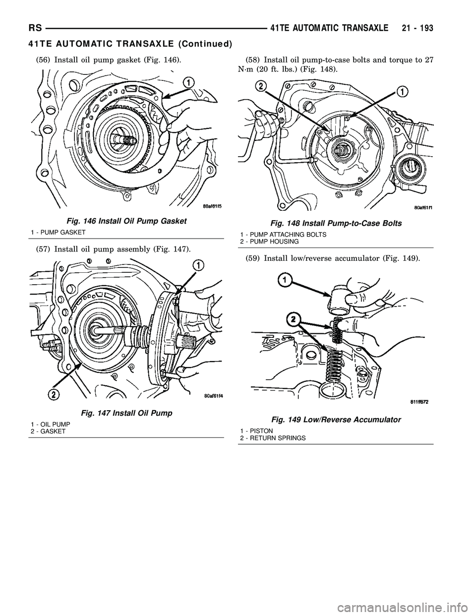
(56) Install oil pump gasket (Fig. 146).
(57) Install oil pump assembly (Fig. 147).(58) Install oil pump-to-case bolts and torque to 27
N´m (20 ft. lbs.) (Fig. 148).
(59) Install low/reverse accumulator (Fig. 149).
Fig. 146 Install Oil Pump Gasket
1 - PUMP GASKET
Fig. 147 Install Oil Pump
1 - OIL PUMP
2 - GASKET
Fig. 148 Install Pump-to-Case Bolts
1 - PUMP ATTACHING BOLTS
2 - PUMP HOUSING
Fig. 149 Low/Reverse Accumulator
1 - PISTON
2 - RETURN SPRINGS
RS41TE AUTOMATIC TRANSAXLE21 - 193
41TE AUTOMATIC TRANSAXLE (Continued)
Page 1656 of 2339

(64) Install and torque valve body-to-case bolts to
12 N´m (105 in. lbs.) (Fig. 154).
(65) Install oil filter and new o-ring (Fig. 155).(66) Apply an 1/8º bead of MopartATF RTV (MS-
GF41) to oil pan and immediately install to case (Fig.
156).
(67) Install oil pan-to-case bolts and torque to 19
N´m (165 in. lbs.).
(68) Install solenoid/pressure switch assembly and
gasket to case (Fig. 157).
Fig. 154 Install Valve Body-to-Case Bolts
1 - VALVE BODY ATTACHING BOLTS (18)
2 - VALVE BODY
Fig. 155 Install Oil Filter
1 - OIL FILTER
2 - O-RING
Fig. 156 Install Oil Pan
1 - OIL PAN
2 - 1/8 INCH BEAD OF MOPARTATF RTV (MS-GF41)
3 - OIL FILTER
Fig. 157 Solenoid/Pressure Switch Assembly and
Gasket
1 - SOLENOID/PRESSURE SWITCH ASSEMBLY
2 - GASKET
RS41TE AUTOMATIC TRANSAXLE21 - 195
41TE AUTOMATIC TRANSAXLE (Continued)