ECO mode CHRYSLER VOYAGER 2005 Owner's Manual
[x] Cancel search | Manufacturer: CHRYSLER, Model Year: 2005, Model line: VOYAGER, Model: CHRYSLER VOYAGER 2005Pages: 2339, PDF Size: 59.69 MB
Page 459 of 2339
REMOVAL
(1) Disconnect and isolate the battery negative
cable.
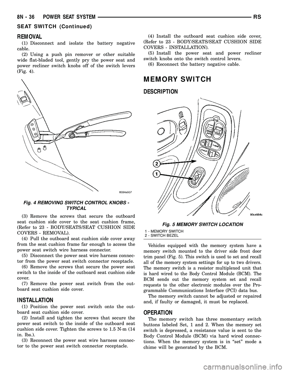
(2) Using a push pin remover or other suitable
wide flat-bladed tool, gently pry the power seat and
power recliner switch knobs off of the switch levers
(Fig. 4).
(3) Remove the screws that secure the outboard
seat cushion side cover to the seat cushion frame,
(Refer to 23 - BODY/SEATS/SEAT CUSHION SIDE
COVERS - REMOVAL).
(4) Pull the outboard seat cushion side cover away
from the seat cushion frame far enough to access the
power seat switch wire harness connector.
(5) Disconnect the power seat wire harness connec-
tor from the power seat switch connector receptacle.
(6) Remove the screws that secure the power seat
switch to the inside of the outboard seat cushion side
cover.
(7) Remove the power seat switch from the out-
board seat cushion side cover.
INSTALLATION
(1) Position the power seat switch onto the out-
board seat cushion side cover.
(2) Install and tighten the screws that secure the
power seat switch to the inside of the outboard seat
cushion side cover. Tighten the screws to 1.5 N´m (14
in. lbs.).
(3) Reconnect the power seat wire harness connec-
tor to the power seat switch connector receptacle.(4) Install the outboard seat cushion side cover,
(Refer to 23 - BODY/SEATS/SEAT CUSHION SIDE
COVERS - INSTALLATION).
(5) Install the power seat and power recliner
switch knobs onto the switch control levers.
(6) Reconnect the battery negative cable.
MEMORY SWITCH
DESCRIPTION
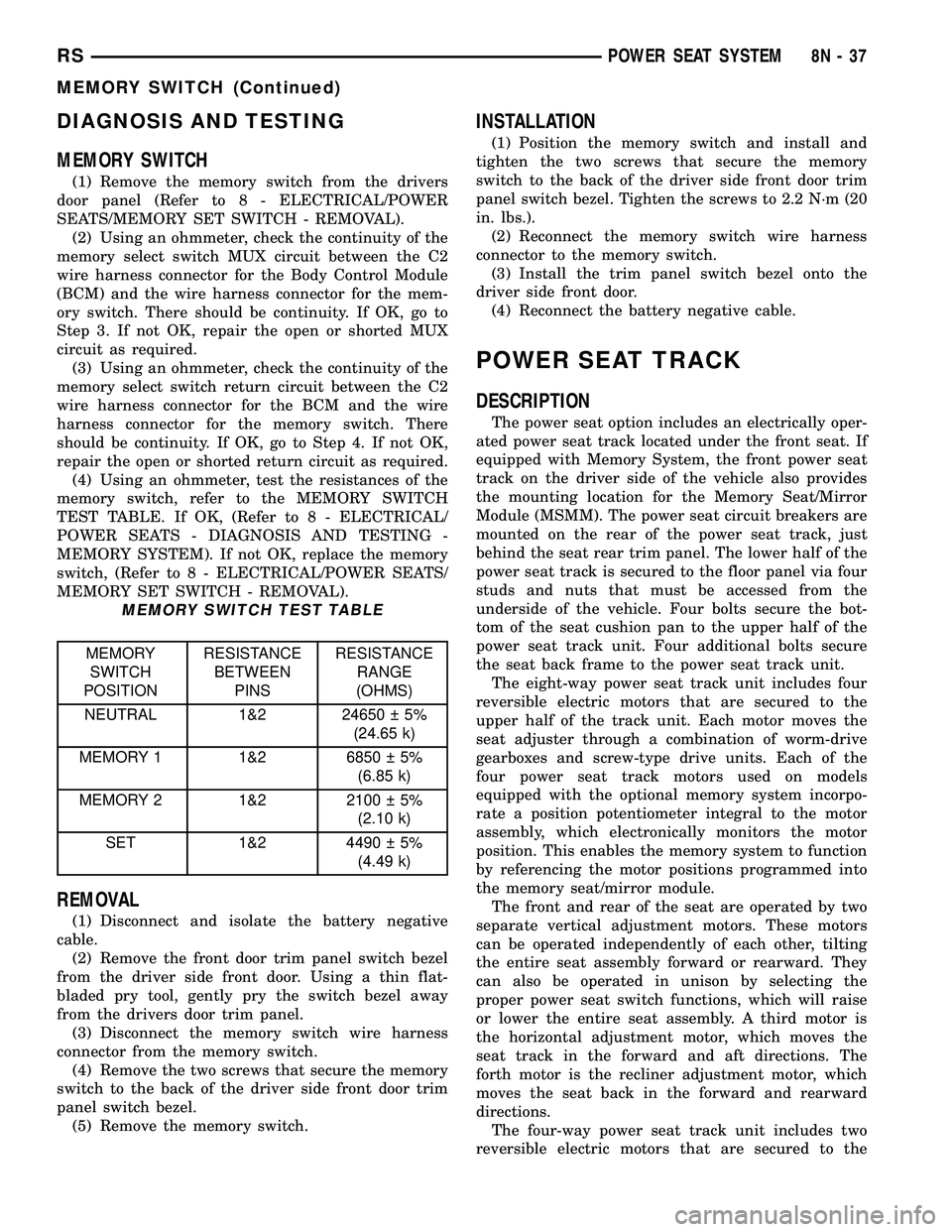
Vehicles equipped with the memory system have a
memory switch mounted to the driver side front door
trim panel (Fig. 5). This switch is used to set and recall
all of the memory system settings for up to two drivers.
The memory switch is a resistor multiplexed unit that
is hard wired to the Body Control Module (BCM). The
BCM sends out the memory system set and recall
requests to the other electronic modules over the Pro-
grammable Communications Interface (PCI) data bus.
The memory switch cannot be adjusted or repaired
and, if faulty or damaged, it must be replaced.
OPERATION
The memory switch has three momentary switch
buttons labeled Set, 1 and 2. When the memory set
switch is depressed, a resistance value is sent to the
Body Control Module (BCM) via hard wired connec-
tions. When the memory system is in ªsetº mode a
chime will be generated by the BCM.
Fig. 4 REMOVING SWITCH CONTROL KNOBS -
TYPICAL
Fig. 5 MEMORY SWITCH LOCATION
1 - MEMORY SWITCH
2 - SWITCH BEZEL
8N - 36 POWER SEAT SYSTEMRS
SEAT SWITCH (Continued)
Page 460 of 2339
DIAGNOSIS AND TESTING
MEMORY SWITCH
(1) Remove the memory switch from the drivers
door panel (Refer to 8 - ELECTRICAL/POWER
SEATS/MEMORY SET SWITCH - REMOVAL).
(2) Using an ohmmeter, check the continuity of the
memory select switch MUX circuit between the C2
wire harness connector for the Body Control Module
(BCM) and the wire harness connector for the mem-
ory switch. There should be continuity. If OK, go to
Step 3. If not OK, repair the open or shorted MUX
circuit as required.
(3) Using an ohmmeter, check the continuity of the
memory select switch return circuit between the C2
wire harness connector for the BCM and the wire
harness connector for the memory switch. There
should be continuity. If OK, go to Step 4. If not OK,
repair the open or shorted return circuit as required.
(4) Using an ohmmeter, test the resistances of the
memory switch, refer to the MEMORY SWITCH
TEST TABLE. If OK, (Refer to 8 - ELECTRICAL/
POWER SEATS - DIAGNOSIS AND TESTING -
MEMORY SYSTEM). If not OK, replace the memory
switch, (Refer to 8 - ELECTRICAL/POWER SEATS/
MEMORY SET SWITCH - REMOVAL).
MEMORY SWITCH TEST TABLE
MEMORY
SWITCH
POSITIONRESISTANCE
BETWEEN
PINSRESISTANCE
RANGE
(OHMS)
NEUTRAL 1&2 24650 5%
(24.65 k)
MEMORY 1 1&2 6850 5%
(6.85 k)
MEMORY 2 1&2 2100 5%
(2.10 k)
SET 1&2 4490 5%
(4.49 k)
REMOVAL
(1) Disconnect and isolate the battery negative
cable.
(2) Remove the front door trim panel switch bezel
from the driver side front door. Using a thin flat-
bladed pry tool, gently pry the switch bezel away
from the drivers door trim panel.
(3) Disconnect the memory switch wire harness
connector from the memory switch.
(4) Remove the two screws that secure the memory
switch to the back of the driver side front door trim
panel switch bezel.
(5) Remove the memory switch.
INSTALLATION
(1) Position the memory switch and install and
tighten the two screws that secure the memory
switch to the back of the driver side front door trim
panel switch bezel. Tighten the screws to 2.2 N´m (20
in. lbs.).
(2) Reconnect the memory switch wire harness
connector to the memory switch.
(3) Install the trim panel switch bezel onto the
driver side front door.
(4) Reconnect the battery negative cable.
POWER SEAT TRACK
DESCRIPTION
The power seat option includes an electrically oper-
ated power seat track located under the front seat. If
equipped with Memory System, the front power seat
track on the driver side of the vehicle also provides
the mounting location for the Memory Seat/Mirror
Module (MSMM). The power seat circuit breakers are
mounted on the rear of the power seat track, just
behind the seat rear trim panel. The lower half of the
power seat track is secured to the floor panel via four
studs and nuts that must be accessed from the
underside of the vehicle. Four bolts secure the bot-
tom of the seat cushion pan to the upper half of the
power seat track unit. Four additional bolts secure
the seat back frame to the power seat track unit.
The eight-way power seat track unit includes four
reversible electric motors that are secured to the
upper half of the track unit. Each motor moves the
seat adjuster through a combination of worm-drive
gearboxes and screw-type drive units. Each of the
four power seat track motors used on models
equipped with the optional memory system incorpo-
rate a position potentiometer integral to the motor
assembly, which electronically monitors the motor
position. This enables the memory system to function
by referencing the motor positions programmed into
the memory seat/mirror module.
The front and rear of the seat are operated by two
separate vertical adjustment motors. These motors
can be operated independently of each other, tilting
the entire seat assembly forward or rearward. They
can also be operated in unison by selecting the
proper power seat switch functions, which will raise
or lower the entire seat assembly. A third motor is
the horizontal adjustment motor, which moves the
seat track in the forward and aft directions. The
forth motor is the recliner adjustment motor, which
moves the seat back in the forward and rearward
directions.
The four-way power seat track unit includes two
reversible electric motors that are secured to the
RSPOWER SEAT SYSTEM8N-37
MEMORY SWITCH (Continued)
Page 470 of 2339

CONDITION POSSIBLE CAUSES CORRECTION
Full open switch inoperative, replace hold
open latch assembly
Replace motor assembly. if necessary
Door does not stay open Inoperative hold open latch assembly Check wire/cable connections
Replace hold open latch, if necessary
Inoperative hold open latch striker Replace hold open latch striker, if necessary
High inside/outside opening
effortInoperative latch assembly Check wire connections and for blown fuse
Check cable connections
Check for foreign matter preventing the
operation of latch assembly
Troubleshoot using body diagnostic manual
Replace latch assembly, if necessary
Inoperative inside/outside handle
assemblyGo to that9POSSIBLE CAUSE9and review
9CORRECTIONS9
Binding or sticking of components Establish location of binding and replace
necessary components
Door continues to cinch
closed during power modeInoperative latch assembly Check wire connections and for blown fuse
Check for foreign matter preventing the
operation of latch assembly
Troubleshoot using body diagnostic manual
Replace latch assembly, if necessary
Inoperative sliding door control module
or BCMDisconnect then reconnect battery negative
cable to reset module. Cycle door, if no
function exists check for loose wire
connections, see Body Diagnostic Manual for
detailed procedures
Wiring problems (system or vehicle) Troubleshoot using the appropriate wiring
information
Door continues to open
during power mode (runaway
motor)Inoperative sliding door control module
or BCMDisconnect then reconnect battery negative
cable to reset module. Cycle door, if no
function exists check for loose wire
connections, see Body Diagnostic Manual for
detailed procedures
Inoperative hold open latch assembly Check wire/cable connections
Replace hold open latch, if necessary
Inoperative drive assembly Remove lower drive unit and check for no
drive condition
Wiring problems (system or vehicle) Troubleshoot using electrical schematics.
Refer to wiring diagrams
Door opens very slowly Inoperative door motor assembly Check wire/cable connections
Replace motor assembly, if necessary
RSPOWER SLIDING DOOR SYSTEM8N-47
POWER SLIDING DOOR SYSTEM (Continued)
Page 489 of 2339
SEAT BELT & RETRACTOR - SECOND ROW -
RIGHT OUTBOARD
REMOVAL.............................40
INSTALLATION.........................40
SEAT BELT & RETRACTOR - SECOND ROW -
RIGHT OUTBOARD WITH REAR HVAC - LWB
REMOVAL.............................41
INSTALLATION.........................41
SEAT BELT & RETRACTOR - SECOND ROW -
LEFT OUTBOARD
REMOVAL.............................42INSTALLATION.........................42
SEAT BELT TENSIONER
DESCRIPTION.........................43
OPERATION...........................43
SEAT WEIGHT BLADDER & PRESSURE
SENSOR
DESCRIPTION.........................43
OPERATION...........................44
RESTRAINTS
DESCRIPTION
This vehicle is equipped with a Frontal Impact Air-
bag System, which utilizes the driver/passenger air-
bags, two front impact sensors, and seat belt
tensioners located in the front seat belt buckles. This
system is designed to protect occupants in the event
of a front impact collision. These airbags are all ser-
viceable parts. The tensioners are integral to the
front seat belt buckles. If these pyrotechnics are
deployed or defective, they must be replaced.
Vehicles equipped with the Side Impact Airbag
System utilize a curtain airbag, three side impact
sensors, and the Occupant Restraint Controller
(ORC) to determine if the airbag should be deployed.
Following a side impact event where the side airbag
was deployed, the headliner as well as the curtain
airbag must be replaced.
The occupant restraints include both active and
passive types. Active restraints are those which
require the vehicle occupants to take some action to
employ, such as fastening a seat belt; while passive
restraints require no action by the vehicle occupants
to be employed.
ACTIVE RESTRAINTS
The active restraints include:
²Front Seat Belts- Both front seating positions
are equipped with three-point seat belt systems
employing a lower B-pillar mounted inertia latch-
type retractor, height-adjustable upper B-pillar
mounted turning loops, a fixed lower seat belt anchor
secured to the lower B-pillar, and a traveling end-re-
lease buckle secured to the inboard side of the seat
cushion frame. The driver side front seat belt buckle
includes an integral Hall-effect seat belt switch that
detects whether the driver side front seat belt has
been fastened.²Rear Seat Belts- Both outboard rear second
and third seating positions are equipped with three-
point seat belt systems. The outboard seating posi-
tion belts employ a lower C or D-pillar mounted
inertia latch-type retractor, a fixed position upper C
or D-pillar mounted turning loop, and a fixed lower
seat belt anchor secured to the inboard side of the
seat cushion frame.
²Child Restraint Anchors- Also equipped in
this vehicle are two, fixed-position, child seat upper
tether anchors located on the lower seat cushion, in
the rear of the lower seat cushion. There is one
anchor integral to the back of the third row seat back
panel, one on each seat back panel. Two lower second
row anchors are also provided for each rear outboard
seating position. The lower anchors are integral to
the seat cushion frame and are accessed from the
front of the second row seat where the seat back
meets the seat cushion.
PASSIVE RESTRAINTS
The passive restraints available for this model
include the following:
²Dual Front Airbags- Multistage driver. front
passenger, and driver knee blocker airbags are avail-
able for this model. This airbag system is a passive,
inflatable, Supplemental Restraint System (SRS) and
vehicles with this equipment can be readily identified
by the ªSRS - AIRBAGº logo molded into the driver
airbag trim cover in the center of the steering wheel
and also into the passenger airbag door on the
instrument panel above the glove box. Vehicles with
the airbag system can also be identified by the airbag
indicator, which will illuminate in the instrument
cluster for about seven seconds as a bulb test each
time the ignition switch is turned to the ON position.
A pyrotechnic-type seat belt tensioner is integral to
the driver and passenger front seat belt buckle of all
models equipped with dual front airbags.
8O - 2 RESTRAINTSRS
Page 495 of 2339
WARNING: Never replace both the Occupant Restraint
Controller (ORC) and the Occupant Classification Mod-
ule (OCM) at the same time. If both require replace-
ment, replace one, then perform the Airbag System
test (Refer to 8 - ELECTRICAL/RESTRAINTS - DIAGNO-
SIS AND TESTING - AIRBAG SYSTEM) before replac-
ing the other. Both the ORC and the OCM store
Occupant Classification System (OCS) calibration
data, which they transfer to one another when one of
them is replaced. If both are replaced at the same
time, an irreversible fault will be set in both modules
and the OCS may malfunction and result in personal
injury or death.
Whether replaced or not, the OCS must be re-ze-
roed to make sure that the system in within proper
parameters to sense the occupants weight correctly.
WARNING: Do not connect the battery negative
cable (Refer to 8 - ELECTRICAL/RESTRAINTS -
DIAGNOSIS AND TESTING - AIRBAG SYSTEM). Per-
sonal injury or death may result if the system test
is not performed first.
WARNING: Following successful completion of the
Airbag System test procedure, the Occupant Classi-
fication System Verification Test must be done
using a scan tool and the appropriate diagnostic
information. Personal injury or death may result if
the system test is not performed.
SEAT BELTS AND TENSIONERS
After a frontal impact where an airbag has been
deployed due to a collision. the followingMUSTbe
replaced:
²Front Seat Belt Buckle (driver and passenger)
with integral Tensioners.
WARNING: Do not connect the battery negative
cable (Refer to 8 - ELECTRICAL/RESTRAINTS -
DIAGNOSIS AND TESTING - AIRBAG SYSTEM). Per-
sonal injury or death may result if the system test
is not performed first.
All other seat belts should be closely inspected for
cuts, tears, fraying, or damage in any way following
any frontal impact or airbag deployment. The other
seat belts are to be replaced when visible damage is
incurred. Inspect the Lower Anchors and Tether for
CHildren (LATCH) child restraint anchors for dam-
age after an impact event and replace as needed.
CLEAN UP PROCEDURE
Roll or fold the airbag towards its mounting point
(i.e. instrument panel, steering wheel, knee blocker,curtain, or seat back). Then tape the ripped cover
over the deployed airbag if applicable.
Use a vacuum cleaner to remove any residual pow-
der from the vehicle interior. Work from the outside
in to avoid kneeling or sitting in a contaminated
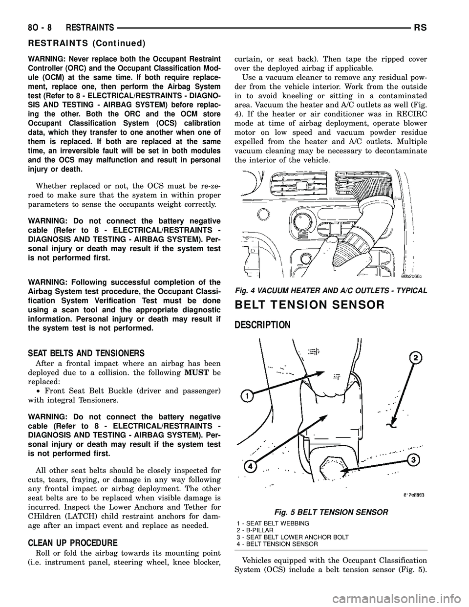
area. Vacuum the heater and A/C outlets as well (Fig.
4). If the heater or air conditioner was in RECIRC
mode at time of airbag deployment, operate blower
motor on low speed and vacuum powder residue
expelled from the heater and A/C outlets. Multiple
vacuum cleaning may be necessary to decontaminate
the interior of the vehicle.
BELT TENSION SENSOR
DESCRIPTION
Vehicles equipped with the Occupant Classification
System (OCS) include a belt tension sensor (Fig. 5).
Fig. 4 VACUUM HEATER AND A/C OUTLETS - TYPICAL
Fig. 5 BELT TENSION SENSOR
1 - SEAT BELT WEBBING
2 - B-PILLAR
3 - SEAT BELT LOWER ANCHOR BOLT
4 - BELT TENSION SENSOR
8O - 8 RESTRAINTSRS
RESTRAINTS (Continued)
Page 496 of 2339
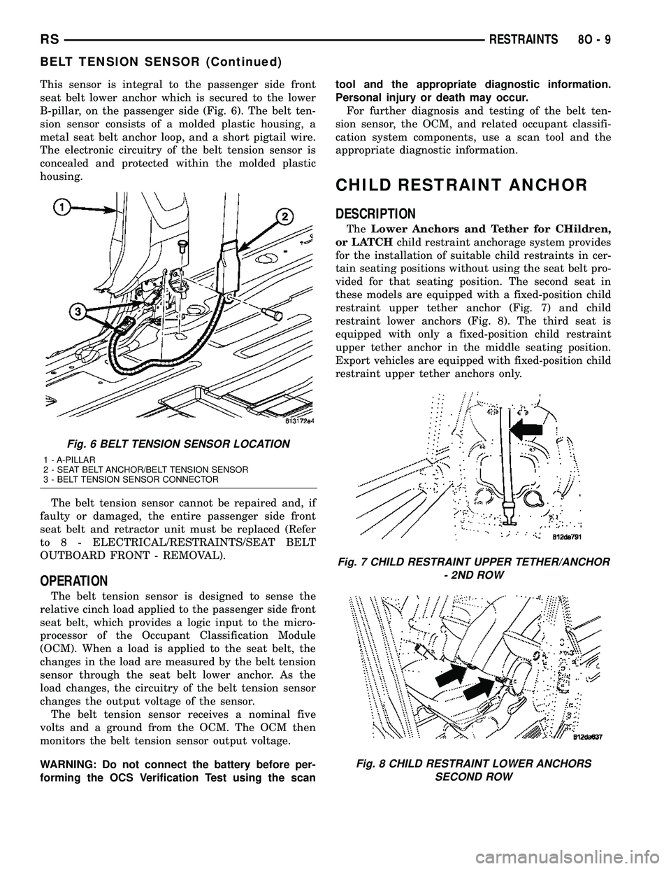
This sensor is integral to the passenger side front
seat belt lower anchor which is secured to the lower
B-pillar, on the passenger side (Fig. 6). The belt ten-
sion sensor consists of a molded plastic housing, a
metal seat belt anchor loop, and a short pigtail wire.
The electronic circuitry of the belt tension sensor is
concealed and protected within the molded plastic
housing.
The belt tension sensor cannot be repaired and, if
faulty or damaged, the entire passenger side front
seat belt and retractor unit must be replaced (Refer
to 8 - ELECTRICAL/RESTRAINTS/SEAT BELT
OUTBOARD FRONT - REMOVAL).
OPERATION
The belt tension sensor is designed to sense the
relative cinch load applied to the passenger side front
seat belt, which provides a logic input to the micro-
processor of the Occupant Classification Module
(OCM). When a load is applied to the seat belt, the
changes in the load are measured by the belt tension
sensor through the seat belt lower anchor. As the
load changes, the circuitry of the belt tension sensor
changes the output voltage of the sensor.
The belt tension sensor receives a nominal five
volts and a ground from the OCM. The OCM then
monitors the belt tension sensor output voltage.
WARNING: Do not connect the battery before per-
forming the OCS Verification Test using the scantool and the appropriate diagnostic information.
Personal injury or death may occur.
For further diagnosis and testing of the belt ten-
sion sensor, the OCM, and related occupant classifi-
cation system components, use a scan tool and the
appropriate diagnostic information.
CHILD RESTRAINT ANCHOR
DESCRIPTION
TheLower Anchors and Tether for CHildren,
or LATCHchild restraint anchorage system provides
for the installation of suitable child restraints in cer-
tain seating positions without using the seat belt pro-
vided for that seating position. The second seat in
these models are equipped with a fixed-position child
restraint upper tether anchor (Fig. 7) and child
restraint lower anchors (Fig. 8). The third seat is
equipped with only a fixed-position child restraint
upper tether anchor in the middle seating position.
Export vehicles are equipped with fixed-position child
restraint upper tether anchors only.
Fig. 6 BELT TENSION SENSOR LOCATION
1 - A-PILLAR
2 - SEAT BELT ANCHOR/BELT TENSION SENSOR
3 - BELT TENSION SENSOR CONNECTOR
Fig. 7 CHILD RESTRAINT UPPER TETHER/ANCHOR
- 2ND ROW
Fig. 8 CHILD RESTRAINT LOWER ANCHORS
SECOND ROW
RSRESTRAINTS8O-9
BELT TENSION SENSOR (Continued)
Page 515 of 2339
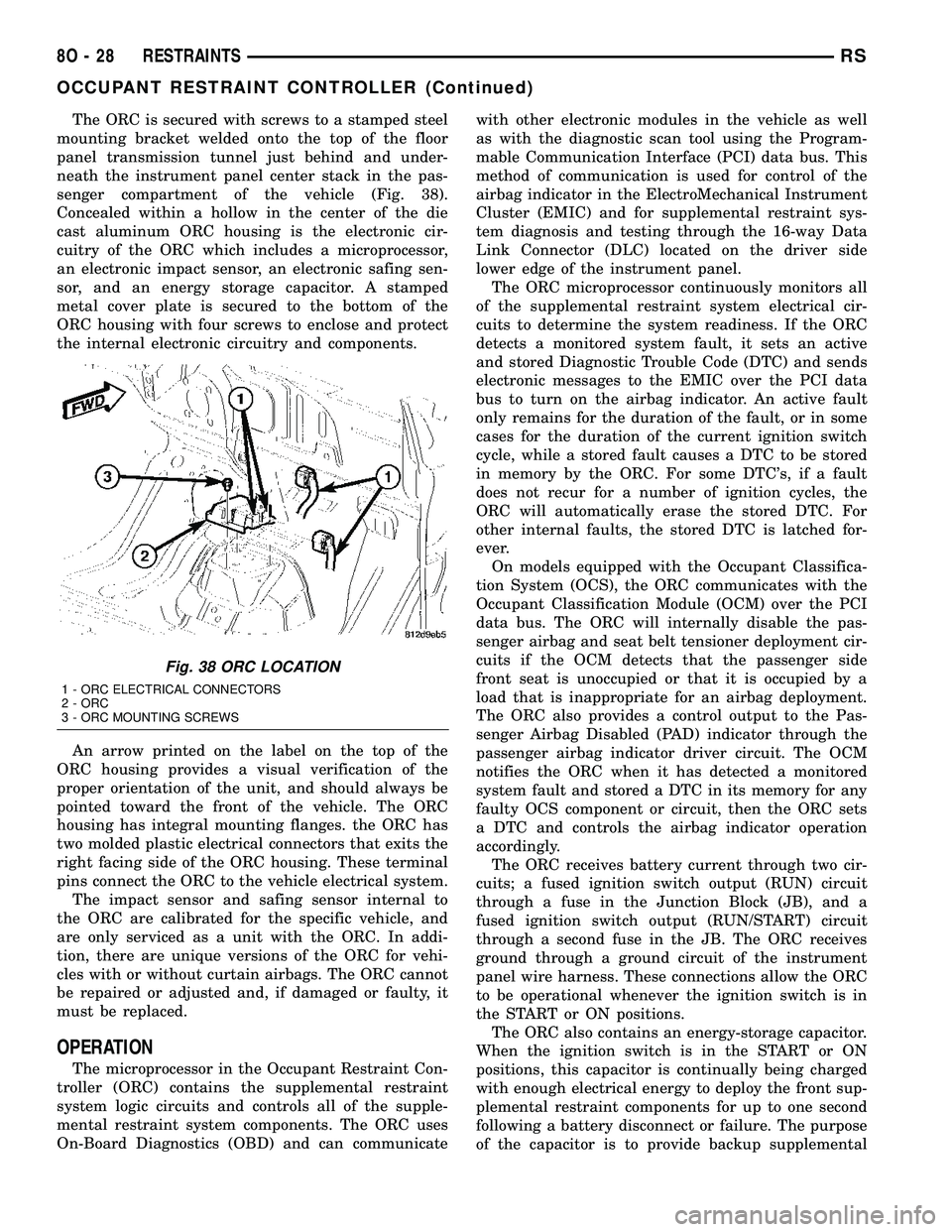
The ORC is secured with screws to a stamped steel
mounting bracket welded onto the top of the floor
panel transmission tunnel just behind and under-
neath the instrument panel center stack in the pas-
senger compartment of the vehicle (Fig. 38).
Concealed within a hollow in the center of the die
cast aluminum ORC housing is the electronic cir-
cuitry of the ORC which includes a microprocessor,
an electronic impact sensor, an electronic safing sen-
sor, and an energy storage capacitor. A stamped
metal cover plate is secured to the bottom of the
ORC housing with four screws to enclose and protect
the internal electronic circuitry and components.
An arrow printed on the label on the top of the
ORC housing provides a visual verification of the
proper orientation of the unit, and should always be
pointed toward the front of the vehicle. The ORC
housing has integral mounting flanges. the ORC has
two molded plastic electrical connectors that exits the
right facing side of the ORC housing. These terminal
pins connect the ORC to the vehicle electrical system.
The impact sensor and safing sensor internal to
the ORC are calibrated for the specific vehicle, and
are only serviced as a unit with the ORC. In addi-
tion, there are unique versions of the ORC for vehi-
cles with or without curtain airbags. The ORC cannot
be repaired or adjusted and, if damaged or faulty, it
must be replaced.
OPERATION
The microprocessor in the Occupant Restraint Con-
troller (ORC) contains the supplemental restraint
system logic circuits and controls all of the supple-
mental restraint system components. The ORC uses
On-Board Diagnostics (OBD) and can communicatewith other electronic modules in the vehicle as well
as with the diagnostic scan tool using the Program-
mable Communication Interface (PCI) data bus. This
method of communication is used for control of the
airbag indicator in the ElectroMechanical Instrument
Cluster (EMIC) and for supplemental restraint sys-
tem diagnosis and testing through the 16-way Data
Link Connector (DLC) located on the driver side
lower edge of the instrument panel.
The ORC microprocessor continuously monitors all
of the supplemental restraint system electrical cir-
cuits to determine the system readiness. If the ORC
detects a monitored system fault, it sets an active
and stored Diagnostic Trouble Code (DTC) and sends
electronic messages to the EMIC over the PCI data
bus to turn on the airbag indicator. An active fault
only remains for the duration of the fault, or in some
cases for the duration of the current ignition switch
cycle, while a stored fault causes a DTC to be stored
in memory by the ORC. For some DTC's, if a fault
does not recur for a number of ignition cycles, the
ORC will automatically erase the stored DTC. For
other internal faults, the stored DTC is latched for-
ever.
On models equipped with the Occupant Classifica-
tion System (OCS), the ORC communicates with the
Occupant Classification Module (OCM) over the PCI
data bus. The ORC will internally disable the pas-
senger airbag and seat belt tensioner deployment cir-
cuits if the OCM detects that the passenger side
front seat is unoccupied or that it is occupied by a
load that is inappropriate for an airbag deployment.
The ORC also provides a control output to the Pas-
senger Airbag Disabled (PAD) indicator through the
passenger airbag indicator driver circuit. The OCM
notifies the ORC when it has detected a monitored
system fault and stored a DTC in its memory for any
faulty OCS component or circuit, then the ORC sets
a DTC and controls the airbag indicator operation
accordingly.
The ORC receives battery current through two cir-
cuits; a fused ignition switch output (RUN) circuit
through a fuse in the Junction Block (JB), and a
fused ignition switch output (RUN/START) circuit
through a second fuse in the JB. The ORC receives
ground through a ground circuit of the instrument
panel wire harness. These connections allow the ORC
to be operational whenever the ignition switch is in
the START or ON positions.
The ORC also contains an energy-storage capacitor.
When the ignition switch is in the START or ON
positions, this capacitor is continually being charged
with enough electrical energy to deploy the front sup-
plemental restraint components for up to one second
following a battery disconnect or failure. The purpose
of the capacitor is to provide backup supplemental
Fig. 38 ORC LOCATION
1 - ORC ELECTRICAL CONNECTORS
2 - ORC
3 - ORC MOUNTING SCREWS
8O - 28 RESTRAINTSRS
OCCUPANT RESTRAINT CONTROLLER (Continued)
Page 533 of 2339
NOTE: Turning the system off by depressing the
OFF switch or turning off the ignition switch will
erase the set speed stored in the PCM.
For added safety, the speed control system is pro-
grammed to disengage for any of the following condi-
tions:
²An indication of Park or Neutral
²A rapid increase rpm (indicates that the clutch
has been disengaged)
²Excessive engine rpm (indicates that the trans-
mission may be in a low gear)
²The speed signal increases at a rate of 10 mph
per second (indicates that the co-efficient of friction
between the road surface and tires is extremely low)
²The speed signal decreases at a rate of 10 mph
per second (indicates that the vehicle may have
decelerated at an extremely high rate)
²If the actual speed is greater than 20 mph over
the set speed.
²Autostick shifts into 1st or 2nd gear (autostick,
if equipped)
Once the speed control has been disengaged,
depressing the RESUME switch when speed is
greater than 20 mph allows the vehicle to resume
control to the target speed that was stored in the
PCM.
While the speed control is engaged, the driver can
increase the vehicle speed by depressing the ACCEL
switch. The new target speed is stored in the PCM
when the ACCEL switch is released. The PCM also
has a9tap-up9feature in which target speed
increases by 2 mph for each momentary switch acti-
vation of the ACCEL switch. The PCM also provides
a means to decelerate to a new lower target speed
without disengaging speed control. Depress and hold
the COAST switch until the desired speed is reached,
then release the switch.
The PCM also has a ªTap Downº feature in which
target speed decreases at 1 mph for each momentary
switch activation of the coast switch.
OPERATION - INTERACTIVE SPEED CONTROL
(4 Speed EATX Only)
Interactive means that communication between the
PCM and the TCM is taking place, this communica-
tion is internal to the PCM on NGC vehicles. Inter-
active speed control avoids unnecessary shifting for
smoother, quieter operation and when downshifts are
required, makes the shifts smoother.
CLIMBING A GRADE
DESCRIPTION
When climbing a grade the interactive speed con-
trol tries to maintain the set speed by increasing thethrottle opening, while inhibiting/delaying down-
shifts.
OPERATION
If opening the throttle alone cannot maintain the
set speed and the vehicle speed drops more than
three mph below the set speed, the transmission will
downshift to third gear. If the vehicle continues to
lose speed, by more than 6 mph, the transmission
will downshift again to maintain the set speed. After
the vehicle encounters a less-steep grade, or has
crested the grade (reduced the load on the power-
train) and can maintain the set speed at a reduced
throttle position, the transmission will upshift, as
appropriate, until the set speed can be maintained in
Overdrive.
GRADE HUNTING
DESCRIPTION
All vehicles equipped with a four speed automatic
transmission have a grade hunting feature for the
2nd to 3rd gear upshift and the 3rd to Overdrive
upshift.
OPERATION
The PCM on NGC vehicles identifies the power-
train loading conditions and selects the proper gear
to maintain the current vehicle speed. Under moder-
ate loading conditions the transaxle will stay in 3rd
gear until the top of the grade is reached or the pow-
ertrain loading is reduced.
If powertrain loading is severe, the transaxle may
shift into 2nd gear and remain there until power-
train loading is reduced, then a 2nd to 3rd gear
upshift will be scheduled. Grade hunting features
always operate regardless of whether or not the
interactive speed control is engaged.If the interac-
tive speed control is not engaged and power-
train loading is not reduced, the driver may
have to completely lift off of the throttle before
an upshift will occur. If the driver does lift off the
throttle to induce an upshift under these conditions,
vehicle speed will reduce and the Overdrive to 3rd
and 3rd to 2nd gear downshifts will reoccur when the
throttle is reapplied. If grade hunting is repeatedly
induced by the driver, transaxle damage may result.
AUTOMATIC SPEED CONTROL OVERSPEED
REDUCTION
DESCRIPTION
Transmission control software includes an auto-
matic speed control overspeed reduction feature. This
maintains vehicle speed at the selected set point
when descending a grade.
8P - 2 SPEED CONTROLRS
SPEED CONTROL (Continued)
Page 544 of 2339
code will be required to complete this task since you
will need it to enter the Secured Access Mode in the
SKREEM. The following steps must be completed
using a DRBIIItscan tool:
(1) Insert the blank key into the ignition and turn
it to the RUN position.
(2) Using a DRBIIItscan tool, select9Theft
Alarm,99SKREEM,99Miscellaneous,9and then9Pro-
gram New Key.9
(3) Enter the four digit PIN code using the
DRBIIItscan tool. When programming is completed,
the SKREEM will exit Secured Access Mode and the
DRBIIItscan tool will display the results of your
attempt to program the key. One of five distinct
results may be displayed. All five are listed below:
²(Programming Successful(is displayed if the
Sentry Key programming is successful.
²(Learned Key in Ignition(is displayed if the
key in the ignition has already been programmed
into that vehicle's SKREEM.
²(Eight Keys Already Learned (At The Maxi-
mum) Programming Not Done(is displayed if
eight keys have already been programmed into the
SKREEM. In this case, if a new key needs to be
added due to a lost or defective key, the9Erase All
Keys9command (which requires entering the Secured
Access Mode) has to be performed. Following the
9Erase All Keys9command, all keys that will be used
to operate the vehicleMUSTbe reprogrammed to
the SKREEM.
²(Programming Not Attempted(is displayed
after an9Erase All Keys9function is executed.
²(Programming Key Failed(is displayed if fur-
ther diagnosis is required.
To learn additional keys, turn the ignition OFF,
remove the learned key, insert the next new blank
key, and repeat the steps from the beginning.
ªCUSTOMER LEARNº MODE
This feature is only available on domestic vehicles
or those which have a U.S. country code designator.
This procedure requires access to at least two valid
Sentry Keys. If two valid Sentry Keys are not avail-
able, Sentry Key programming will require the use of
a DRBIIItscan tool.
The steps required to program Sentry Keys with
two valid Sentry Keys follows:
(1) Obtain the blank Sentry Key(s) that need to be
programmed. Cut the keys to match the ignition lock
cylinder mechanical key codes.
(2) Insert one of the two valid Sentry Keys into the
ignition switch and turn the ignition switch to the
ON position.
(3) After the ignition switch has been in the ON
position for longer than three seconds, but no more
than fifteen seconds, cycle the ignition switch back tothe OFF position. Replace the first valid Sentry Key
in the ignition lock cylinder with the second valid
Sentry Key and turn the ignition switch back to the
ON position. The second valid Sentry Key must be
inserted within 15 seconds of removing the first valid
Sentry key.
(4) About ten seconds after the completion of Step
3, the indicator light will start to flash and a single
audible chime tone will sound to indicate that the
system has entered the9Customer Learn9program-
ming mode.
(5) Within sixty seconds of entering the9Customer
Learn9programming mode, turn the ignition switch
to the OFF position, replace the valid Sentry Key
with a blank Sentry Key transponder, and turn the
ignition switch back to the ON position.
(6) About ten seconds after the completion of Step
5, a single audible chime tone will sound and the
indicator light will stop flashing and stay on solid for
three seconds and then turn off to indicate that the
blank Sentry Key has been successfully programmed.
The SKREES will immediately exit the9Customer
Learn9programming mode and the vehicle may be
started using the newly programmed Sentry Key.
NOTE: The Remote Keyless Entry (RKE) Transmitter
will also be programmed during this procedure.
These steps must be completed in their entirety for
each additional Sentry Key to be programmed. If any
of the above steps are not completed in the given
sequence, or within the allotted time, the SKREES
will exit the9Customer Learn9programming mode
and the programming will be unsuccessful. The
SKREES will also automatically exit the9Customer
Learn9programming mode if:
²It sees a non-blank Sentry Key when it should
see a blank.
²If it has already programmed four (4) valid Sen-
try Keys.
²If the ignition switch is turned to the OFF posi-
tion for more than about fifty (50) seconds.
NOTE: If you attempt to start the vehicle while in
ªCustomer Learnº mode (LED flashing), the vehicle
will behave as though an invalid key is being used
(i.e. the engine will stall after two (2) seconds of
running). No faults will be logged.
NOTE: Once a Sentry Key has been programmed to
a particular vehicle, it cannot be used on any other
vehicle.
RSVEHICLE THEFT SECURITY8Q-7
TRANSPONDER KEY (Continued)
Page 545 of 2339
VTSS/SKIS INDICATOR LAMP
DESCRIPTION
The Sentry Key Remote Entry System (SKREES)
uses an indicator light to convey information on the
status of the system to the customer. This light is
shared with the Vehicle Theft Security System
(VTSS). The light is located in the Mechanical
Instrument Cluster (MIC). The VTSS status is con-
trolled by the Body Control Module (BCM), via Pro-
grammable Communication Interface (PCI) data bus
communication with the MIC, based upon messages
it receives from the Sentry Key Remote Entry Mod-
ule (SKREEM) on the PCI data bus.
OPERATION
The Mechanical Instrument Cluster (MIC) per-
forms a four second bulb check via PCI communica-
tion with the Sentry Key Remote Entry Module
(SKREEM). After the bulb check, the lamp is con-
trolled according to SKREEM messages. Then, the
SKREEM sends messages to the BCM to operate thelight based upon the results of the Sentry Key
Remote Entry System (SKREES) self tests. The light
may be actuated in two possible ways, flashing or on
solid. If the light comes on and stays on solid after a
power-up test, this indicates that the SKREEM has
detected a system malfunction. If the SKREEM
detects an invalid key when the ignition switch is
moved to the ON position, it sends a message on the
PCI bus to the MIC, to flash the light. The SKREEM
can also send a message to flash the light and gen-
erate a single audible chime at the same time. These
two events occurring simultaneously indicate that
the SKIS has been placed into the9Customer Learn9
mode (Refer to 8 - ELECTRICAL/VEHICLE THEFT
SECURITY/TRANSPONDER KEY - STANDARD
PROCEDURE). If the light comes on and stays on
after the power-up test, diagnosis of the SKREES
should be performed using a DRBIIItscan tool and
the appropriate Body Diagnostic Procedures informa-
tion. The light is a Light Emitting Diode (LED) and
is not a serviceable component.
8Q - 8 VEHICLE THEFT SECURITYRS