ECO mode CHRYSLER VOYAGER 2005 Workshop Manual
[x] Cancel search | Manufacturer: CHRYSLER, Model Year: 2005, Model line: VOYAGER, Model: CHRYSLER VOYAGER 2005Pages: 2339, PDF Size: 59.69 MB
Page 1568 of 2339
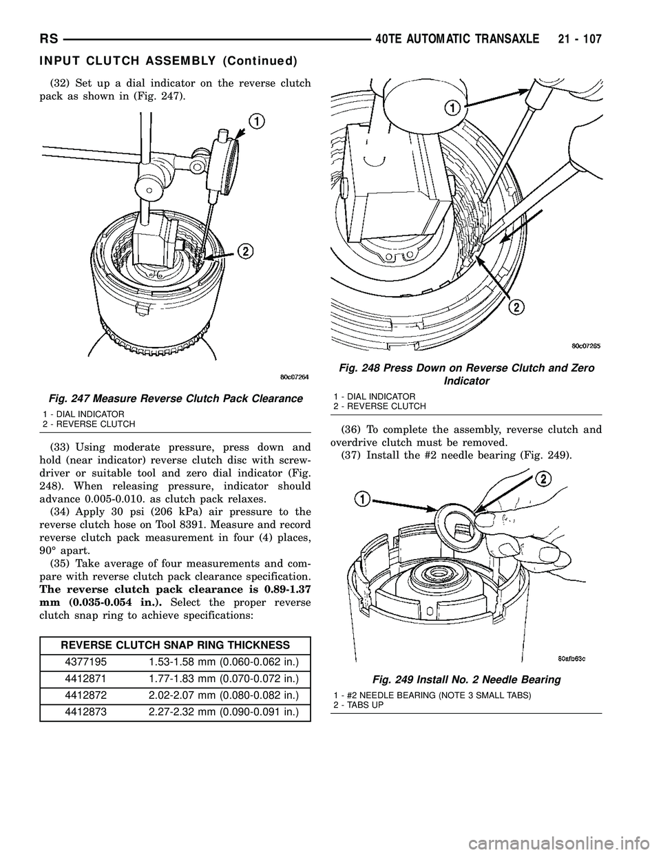
(32) Set up a dial indicator on the reverse clutch
pack as shown in (Fig. 247).
(33) Using moderate pressure, press down and
hold (near indicator) reverse clutch disc with screw-
driver or suitable tool and zero dial indicator (Fig.
248). When releasing pressure, indicator should
advance 0.005-0.010. as clutch pack relaxes.
(34) Apply 30 psi (206 kPa) air pressure to the
reverse clutch hose on Tool 8391. Measure and record
reverse clutch pack measurement in four (4) places,
90É apart.
(35) Take average of four measurements and com-
pare with reverse clutch pack clearance specification.
The reverse clutch pack clearance is 0.89-1.37
mm (0.035-0.054 in.).Select the proper reverse
clutch snap ring to achieve specifications:
REVERSE CLUTCH SNAP RING THICKNESS
4377195 1.53-1.58 mm (0.060-0.062 in.)
4412871 1.77-1.83 mm (0.070-0.072 in.)
4412872 2.02-2.07 mm (0.080-0.082 in.)
4412873 2.27-2.32 mm (0.090-0.091 in.)(36) To complete the assembly, reverse clutch and
overdrive clutch must be removed.
(37) Install the #2 needle bearing (Fig. 249).
Fig. 247 Measure Reverse Clutch Pack Clearance
1 - DIAL INDICATOR
2 - REVERSE CLUTCH
Fig. 248 Press Down on Reverse Clutch and Zero
Indicator
1 - DIAL INDICATOR
2 - REVERSE CLUTCH
Fig. 249 Install No. 2 Needle Bearing
1 - #2 NEEDLE BEARING (NOTE 3 SMALL TABS)
2 - TABS UP
RS40TE AUTOMATIC TRANSAXLE21 - 107
INPUT CLUTCH ASSEMBLY (Continued)
Page 1714 of 2339
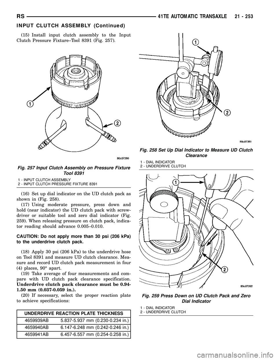
(15) Install input clutch assembly to the Input
Clutch Pressure Fixture±Tool 8391 (Fig. 257).
(16) Set up dial indicator on the UD clutch pack as
shown in (Fig. 258).
(17) Using moderate pressure, press down and
hold (near indicator) the UD clutch pack with screw-
driver or suitable tool and zero dial indicator (Fig.
259). When releasing pressure on clutch pack, indica-
tor reading should advance 0.005±0.010.
CAUTION: Do not apply more than 30 psi (206 kPa)
to the underdrive clutch pack.
(18) Apply 30 psi (206 kPa) to the underdrive hose
on Tool 8391 and measure UD clutch clearance. Mea-
sure and record UD clutch pack measurement in four
(4) places, 90É apart.
(19) Take average of four measurements and com-
pare with UD clutch pack clearance specification.
Underdrive clutch pack clearance must be 0.94-
1.50 mm (0.037-0.059 in.).
(20) If necessary, select the proper reaction plate
to achieve specifications:
UNDERDRIVE REACTION PLATE THICKNESS
4659939AB 5.837-5.937 mm (0.230-0.234 in.)
4659940AB 6.147-6.248 mm (0.242-0.246 in.)
4659941AB 6.457-6.557 mm (0.254-0.258 in.)
Fig. 257 Input Clutch Assembly on Pressure Fixture
Tool 8391
1 - INPUT CLUTCH ASSEMBLY
2 - INPUT CLUTCH PRESSURE FIXTURE 8391
Fig. 258 Set Up Dial Indicator to Measure UD Clutch
Clearance
1 - DIAL INDICATOR
2 - UNDERDRIVE CLUTCH
Fig. 259 Press Down on UD Clutch Pack and Zero
Dial Indicator
1 - DIAL INDICATOR
2 - UNDERDRIVE CLUTCH
RS41TE AUTOMATIC TRANSAXLE21 - 253
INPUT CLUTCH ASSEMBLY (Continued)
Page 1719 of 2339
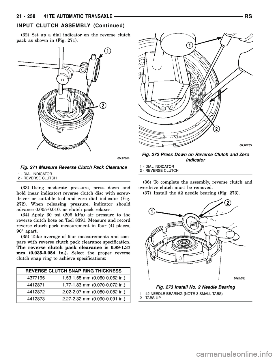
(32) Set up a dial indicator on the reverse clutch
pack as shown in (Fig. 271).
(33) Using moderate pressure, press down and
hold (near indicator) reverse clutch disc with screw-
driver or suitable tool and zero dial indicator (Fig.
272). When releasing pressure, indicator should
advance 0.005-0.010. as clutch pack relaxes.
(34) Apply 30 psi (206 kPa) air pressure to the
reverse clutch hose on Tool 8391. Measure and record
reverse clutch pack measurement in four (4) places,
90É apart.
(35) Take average of four measurements and com-
pare with reverse clutch pack clearance specification.
The reverse clutch pack clearance is 0.89-1.37
mm (0.035-0.054 in.).Select the proper reverse
clutch snap ring to achieve specifications:
REVERSE CLUTCH SNAP RING THICKNESS
4377195 1.53-1.58 mm (0.060-0.062 in.)
4412871 1.77-1.83 mm (0.070-0.072 in.)
4412872 2.02-2.07 mm (0.080-0.082 in.)
4412873 2.27-2.32 mm (0.090-0.091 in.)(36) To complete the assembly, reverse clutch and
overdrive clutch must be removed.
(37) Install the #2 needle bearing (Fig. 273).
Fig. 271 Measure Reverse Clutch Pack Clearance
1 - DIAL INDICATOR
2 - REVERSE CLUTCH
Fig. 272 Press Down on Reverse Clutch and Zero
Indicator
1 - DIAL INDICATOR
2 - REVERSE CLUTCH
Fig. 273 Install No. 2 Needle Bearing
1 - #2 NEEDLE BEARING (NOTE 3 SMALL TABS)
2 - TABS UP
21 - 258 41TE AUTOMATIC TRANSAXLERS
INPUT CLUTCH ASSEMBLY (Continued)
Page 1838 of 2339
INSTALLATION
NOTE: The crossbar assemblies are designed to be
installed in only one way. Check top and bottom
surfaces of the crossbar for the word FRONT and
directional arrows. The directional arrows must
point toward the front of the vehicle.
(1) Place crossbar in position on vehicle.
(2) Work from side to side sliding the crossbar
assembly back a little at a time to ensure it remains
perpendicular to the side rails.
(3) Position first crossbar assembly crossbar at the
second most rearward locator holes. Press the top of
the stanchion lever to lock it into position.
(4) Position the second crossbar assembly in the
second hole from the front. Lock into place.
(5) Place luggage rack riser into position.
(6) Install two fasteners into riser. Tighten fasten-
ers to 4 mm (35 in. lbs.) torque.
REAR QUARTER PANEL/
FENDER AIR EXHAUSTER
DESCRIPTION
Air exhausters, designed to conform to the body
structure, allow air entering at the front of the vehi-
cle to flow out the back. By reducing air pressure
within the vehicle, the exhausters also reduce blower
noise at any given air flow level compared to operat-
ing without them and help reduce door closing effort.
They are located in the lower rear comers of the
body.
REMOVAL
SHORT WHEELBASE
(1) Remove the rear fascia from the body. (Refer to
13 - FRAMES & BUMPERS/BUMPERS/REAR FAS-
CIA - REMOVAL).
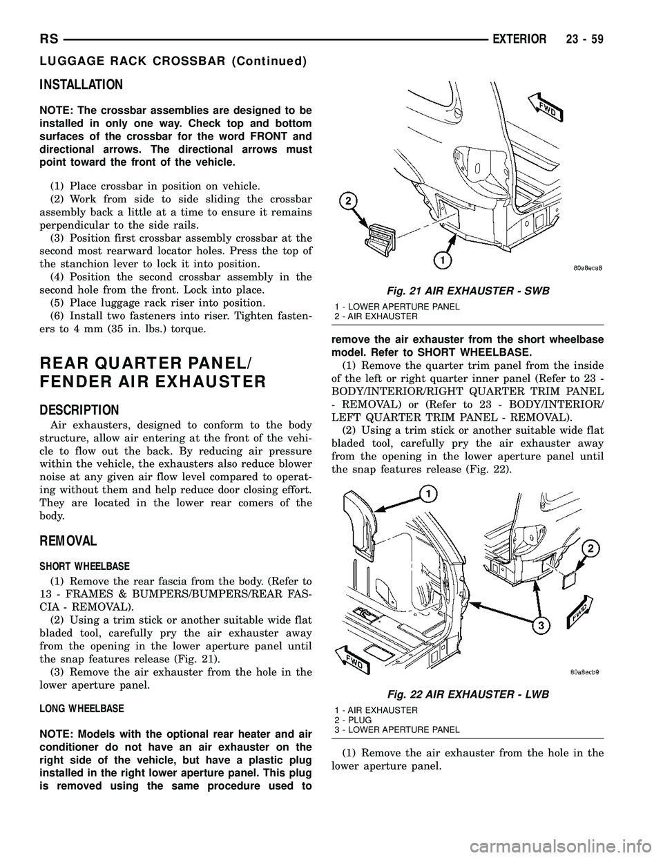
(2) Using a trim stick or another suitable wide flat
bladed tool, carefully pry the air exhauster away
from the opening in the lower aperture panel until
the snap features release (Fig. 21).
(3) Remove the air exhauster from the hole in the
lower aperture panel.
LONG WHEELBASE
NOTE: Models with the optional rear heater and air
conditioner do not have an air exhauster on the
right side of the vehicle, but have a plastic plug
installed in the right lower aperture panel. This plug
is removed using the same procedure used toremove the air exhauster from the short wheelbase
model. Refer to SHORT WHEELBASE.
(1) Remove the quarter trim panel from the inside
of the left or right quarter inner panel (Refer to 23 -
BODY/INTERIOR/RIGHT QUARTER TRIM PANEL
- REMOVAL) or (Refer to 23 - BODY/INTERIOR/
LEFT QUARTER TRIM PANEL - REMOVAL).
(2) Using a trim stick or another suitable wide flat
bladed tool, carefully pry the air exhauster away
from the opening in the lower aperture panel until
the snap features release (Fig. 22).
(1) Remove the air exhauster from the hole in the
lower aperture panel.
Fig. 21 AIR EXHAUSTER - SWB
1 - LOWER APERTURE PANEL
2 - AIR EXHAUSTER
Fig. 22 AIR EXHAUSTER - LWB
1 - AIR EXHAUSTER
2 - PLUG
3 - LOWER APERTURE PANEL
RSEXTERIOR23-59
LUGGAGE RACK CROSSBAR (Continued)
Page 2152 of 2339
HEATING & AIR CONDITIONING
TABLE OF CONTENTS
page page
HEATING & AIR CONDITIONING
DESCRIPTION
ENGINE COOLING SYSTEM
REQUIREMENTS.......................1
HEATER AND AIR CONDITIONER..........1
MANUAL SINGLE ZONE.................2
MANUAL DUAL ZONE...................2
MANUAL THREE ZONE..................2
AUTOMATIC TEMPERATURE CONTROL....3
OPERATION
HEATER AND AIR CONDITIONER..........4
MANUAL SINGLE ZONE.................4
MANUAL DUAL ZONE...................5
MANUAL THREE ZONE..................5AUTOMATIC TEMPERATURE CONTROL....5
DIAGNOSIS AND TESTING
A/C COOL DOWN TEST.................6
A/C PERFORMANCE TEST...............7
HEATER PERFORMANCE TEST..........10
SPECIFICATIONS
A/C SYSTEM.........................11
CONTROLS - FRONT.....................13
CONTROLS - REAR......................33
DISTRIBUTION - FRONT...................42
DISTRIBUTION - REAR....................56
PLUMBING - FRONT.....................64
PLUMBING - REAR......................98
CABIN HEATER........................113
HEATING & AIR
CONDITIONING
DESCRIPTION
ENGINE COOLING SYSTEM REQUIREMENTS
To maintain the performance level of the heating,
ventilation and air conditioning (HVAC) system, the
engine cooling system must be properly maintained.
The use of a bug screen is not recommended. Any
obstructions in front of the radiator or condenser will
reduce the performance of the air conditioning and
engine cooling systems.
The engine cooling system includes the radiator,
thermostat, radiator hoses and the engine coolant
pump. Refer to Cooling for more information before
opening or attempting any service to the engine cool-
ing system.
HEATER AND AIR CONDITIONER
A manually controlled single zone type heating-air
conditioning system, manually controlled dual zone
type heating-air conditioning system, manually con-
trolled three zone type heating-air conditioning sys-
tem or an automatic controlled three zone type
heating-air conditioning system is available on this
model.
All vehicles are equipped with a common heater,
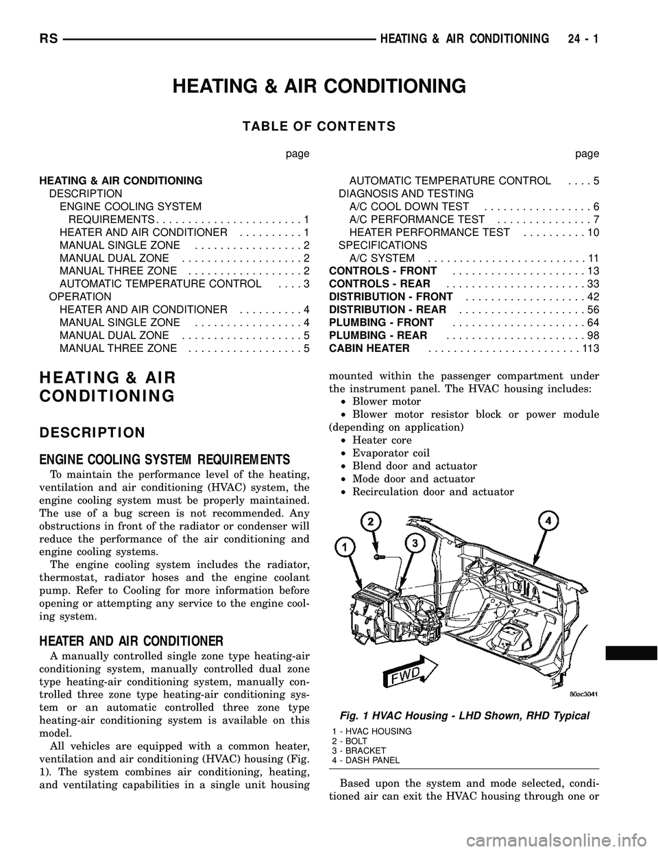
ventilation and air conditioning (HVAC) housing (Fig.
1). The system combines air conditioning, heating,
and ventilating capabilities in a single unit housingmounted within the passenger compartment under
the instrument panel. The HVAC housing includes:
²Blower motor
²Blower motor resistor block or power module
(depending on application)
²Heater core
²Evaporator coil
²Blend door and actuator
²Mode door and actuator
²Recirculation door and actuator
Based upon the system and mode selected, condi-
tioned air can exit the HVAC housing through one or
Fig. 1 HVAC Housing - LHD Shown, RHD Typical
1 - HVAC HOUSING
2 - BOLT
3 - BRACKET
4 - DASH PANEL
RSHEATING & AIR CONDITIONING24-1
Page 2154 of 2339
²a rotary adjustment knob for temperature.
²a rotary adjustment for fan speed control.
AUTOMATIC TEMPERATURE CONTROL
Two different automatic temperature control (ATC)
heating-A/C systems are available for this model
depending on the market.
The Dual-Zone ATC system allows the driver and
front occupants to each select individual comfort tem-
peratures.
The Three-Zone ATC system allows both the driver
and front occupants and the rear intermediate occu-
pants to select individual comfort temperatures.
NOTE: Individual comfort temperatures are the per-
ceived temperature level at the individual seating
areas, NOT the actual passenger compartment air
temperature.
The ATC system includes a particulate air filter.
The filter element is the same size as the A/C evap-
orator to ensure ample capacity. A door at the base of
the HVAC housing below the glove box provides easy
access to the filter element.
The ATC computer utilizes integrated circuitry and
information carried on the programmable communi-
cations interface (PCI) data bus network to monitor
many sensors and switch inputs throughout the vehi-
cle. In response to those inputs, the internal circuitry
and programming of the ATC computer allow it to
control electronic functions and features of the ATC
system. The inputs to the ATC computer are:
²Vehicle Speed/Engine RPM± The ATC com-
puter monitors engine rpm, vehicle speed and mani-
fold absolute pressure information from the
powertrain control module (PCM).
²Coolant Temperature± ATC computer moni-
tors coolant temperature received from the PCM and
converts it to degrees Fahrenheit.
²Ambient Temperature± ATC computer moni-
tors ambient temperature from the compass mini trip
computer (CMTC) and converts it to degrees Fahren-
heit.
²Engine Miscellaneous Sensor Status±ATC
computer monitors A/C disable information from the
PCM.
²Refrigerant Pressure± ATC computer moni-
tors barometric pressure, intake air temperature,
high side pressure and methanol content as broad-
cast by the PCM.
²Door Ajar Status± The ATC computer moni-
tors driver front door, passenger front door, left rear
door, right rear door and liftgate ajar information, as
identified by the body control module (BCM), to
determine if all in-car temperatures should be main-
tained.²Dimming± The ATC computer monitors dim-
ming status from the BCM to determine the required
level of brightness and will dim accordingly.
²Vehicle Odometer± The ATC computer moni-
tors the vehicle odometer information from the BCM
to prevent flashing the vacuum-flourescent (VF) dig-
ital display icons if the manual motor calibration or
manual cool down tests have failed. Flashing of the
display icons will cease when the vehicle odometer is
greater than 3 miles.
²English/Metric± The ATC computer monitors
the English/Metric information broadcast by the
CMTC. The set temp displays for both the front and
rear control heads will be set accordingly.
²Vehicle Identification Number± The ATC
computer monitors the last eight characters of the
VIN broadcast by the PCM and compares it to the
information stored in EEPROM. If it is different, the
new number will be stored over the old one and a
motor calibration shall be initiated.
²A/C System Information± The ATC computer
will send a message for evaporator temperature too
low, fan blower relay status, evaporator sensor fail-
ure, rear window defogger relay and A/C select.
FRONT CONTROL PANEL
The front A/C-heater control and integral computer
is mounted in the instrument panel and contains:
²a power button which allows the system to be
completely turned off. The display is blank when the
system is off.
²a rocker switch that selects a cool-down rate.
LO-AUTO or HI-AUTO are displayed when the sys-
tem is in automatic operation.
²three rocker switches that select comfort temper-
atures from 15É to 30É C (59É to 85É F), which are
shown in the VF digital display. If the set temp is 15É
C (59É F) and the down button is pressed, the set
temp value will become 13É C (55É F) but the display
will show LO. If the set temp is 29É C (85É F) and the
up button is pressed, the set temp value will become
32É C (90É F) but the display will show HIGH. Tem-
peratures can be displayed in either metric or Fahr-
enheit, which is controlled from the overhead console.
²an air conditioning button that allows the com-
pressor to be turned off. A Snowflake symbol is illu-
minated when air conditioning is on, whether under
manual or automatic control.
²an air recirculation button. A Recirculation sym-
bol appears in the display when the button is
pressed, or when the system exceeds 80 percent recir-
culated air under automatic control due to high air
conditioning demand.
²a rear window defogger on/off switch. A graphic
symbol shows when the defroster is on.
RSHEATING & AIR CONDITIONING24-3
HEATING & AIR CONDITIONING (Continued)
Page 2157 of 2339
defogger function will be active for 10 minutes and
can be turned off by a switch press. The defogger will
function while the control is in the ON mode.
²FAN/MODE± The Fan and Mode knobs have
17 manual selectable positions. Manually changing
either of the rotary knobs for mode or fan speed set-
tings makes control of that blower motor manual. If
only one is changed manually, the other remains
under automatic control. Pressing the HI-AUTO/LO-
AUTO rocker switch restores full automatic control.
²BLOWER DELAY TIMER± The word DELAY
is displayed at start-up to signify that the system is
waiting so that cold air will not be blowing. This tells
the operator that it is unnecessary to turn the sys-
tem off, raise the temperature setting or turn the fan
speed setting down to prevent cold air from blowing.
A countdown in minutes and seconds until the engine
is warm enough to begin delivering heat to the pas-
sengers alternates with the DELAY message at 25
second intervals. This countdown is based on actual
measurement of the rate of engine coolant tempera-
ture change. During the delay time, mix mode is
selected and the fan operates at a low speed to keep
the windshield fog free.
²REAR CONTROL (Three-Zone only)± When
the Rear System control knob is moved to the OFF
position, there will be a delay of approximately 1 sec-
ond before the system actually turns off. This delay
is to prevent an undesired blower dropout if the knob
is moved through OFF to the other selections.
REAR CONTROL PANEL ± THREE ZONE ATC
SYSTEM
Primary control of the rear compartment heating-
A/C system for the Three-Zone ATC system is in the
instrument panel center stack. This control allows
the driver to turn the rear heating-A/C system off, or
allows the intermediate seat occupants control of the
rear system by switching to the REAR position, or
provides fully automatic control based on the temper-
ature setting shown on the front control display.
²REAR CONTROL± Selecting automatic control
of the rear unit at the instrument panel, illuminates
a Locked Padlock in the rear control panel display.
Selecting REAR activates the rear control panel and
the Padlock then appears unlocked.
²FAN KNOB± The rear fan control has Off and
AUTO positions and a range of manual speed set-
tings that override the AUTO setting.
²MODE KNOB± The mode control allows inter-
mediate seat occupants to manually override the
automatic mode and select any balance of air flow
between overhead and floor outlets from full over-
head to full floor.
²SET TEMP± The rear set temp control will
operate identical to the front controls. If the frontcontrol rear set temp button is pressed simulta-
neously with the rear control head, then the front
control head press events shall have priority, i.e. if
the front user presses Rear Set Temp down and the
rear user presses Set Temp up, then the rear set
temp will decrease.
DIAGNOSIS AND TESTING
A/C COOL DOWN TEST
The heater-A/C control module can perform an A/C
cool down test, which is a test performed during the
manufacturing process to confirm that the air condi-
tioning system is performing satisfactorily. This test
can also provide a quick confirmation of air condi-
tioning system performance to the service technician.
If the test is completed satisfactorily, no further ser-
vice is required. If the test is failed, proceed to the
A/C Performance Test to confirm the A/C system is
operating properly, or use a DRBIIItscan tool to
diagnose the A/C system control and distribution sys-
tems. Refer to the appropriate diagnostic informa-
tion.
MANUAL TEMPERATURE CONTROL
The front blower speed and rear blower speed (if
equipped with rear HVAC) must be set to High and
the evaporator temperature sensor must be greater
than 13É C (55É F) or the test will fail immediately.
The test is activated by depressing the A/C and Rear
Wipe/Wash buttons simultaneously and holding them
depressed for no less than five seconds. The Rear
Wipe/Wash and A/C LEDs will blink on and off until
the test is complete. If the LEDs stop blinking before
two minutes, then the cool down test has been com-
pleted successfully. If the two minutes expire without
the expansion valve temperature reaching -6É C (20É
F) less than the outside air temperature, then the
cool down test has been failed and further A/C sys-
tem diagnosis is required. If the test is failed, the
LEDs will continue to blink until the vehicle has
been driven for greater than 13 km (8 miles).
AUTOMATIC TEMPERATURE CONTROL
The ambient air temperature in the room where
the vehicle will be tested must be a minimum of 21É
C (70ÉF) for this test. The test is activated by
depressing the A/C and PWR buttons simultaneously
and holding them depressed for no less than four sec-
onds. The snowflake icon and the DELAY text in the
ATC display will blink on and off alternately until
the test is complete. If the snowflake icon and the
DELAY text stop blinking before two minutes, then
the cool down test has been completed successfully. If
the two minutes expire without the evaporator tem-
perature reaching -6É C (20É F) less than the evapo-
24 - 6 HEATING & AIR CONDITIONINGRS
HEATING & AIR CONDITIONING (Continued)
Page 2166 of 2339
(b) If the compressor clutch coil current reading
is four amperes or more, the coil is shorted and
must be replaced.
STANDARD PROCEDURE
CLUTCH INSPECTION
NOTE: The compressor clutch can be serviced in
the vehicle. The refrigerant system can remain fully-
charged during compressor clutch, pulley, or coil
replacement.
Examine the friction surfaces of the clutch pulley
and the clutch plate for wear. The pulley and plate
should be replaced if there is excessive wear or scor-
ing.
If the friction surfaces are oily, inspect the shaft
and nose area of the A/C compressor for refrigerant
oil. If refrigerant oil is found, the compressor shaft
seal is leaking and the A/C compressor must be
replaced.
Check the clutch pulley bearing for roughness or
excessive leakage of grease. Replace the pulley and
bearing assembly, if required.
A/C CLUTCH BREAK-IN
After a new A/C compressor clutch has been
installed, cycle the compressor clutch approximately
twenty times (five seconds on, then five seconds off).
During this procedure, set the A/C-heater controls to
the A/C Recirculation Mode, the blower motor in the
highest speed position, and the engine speed at 1500
to 2000 rpm. This procedure (burnishing) will seat
the opposing friction surfaces of the compressor
clutch, which provides optimum compressor clutch
torque capability.
REMOVAL
NOTE: The compressor clutch can be serviced in
the vehicle. The refrigerant system can remain fully-
charged during compressor clutch, pulley, or coil
replacement.
(1) Disconnect and isolate the negative battery
cable.
(2) Remove the accessory drive belt (Refer to 7 -
COOLING/ACCESSORY DRIVE/DRIVE BELTS -
REMOVAL).
(3) Raise and support the vehicle.
(4) Disconnect the engine wire harness connector
for the compressor clutch coil from the clutch coil pig-
tail wire connector on the top of the A/C compressor.
(5) On models with the 3.3L and 3.8L engines, dis-
engage the retainer on the engine wire harness com-pressor clutch coil take out from the bracket on the
top of the A/C compressor.
(6) On models with the 2.4L, 2.5L and 2.8L
engines, remove all of the compressor mounting bolts
except the upper left (rear of the A/C compressor),
which should only be loosened. Allow the front (pul-
ley end) of the A/C compressor to tilt downward far
enough to access the clutch for removal, then tighten
the loosened upper left compressor mounting bolt.
(7) On models with the 3.3L and 3.8L engines,
remove the two bolts and two nuts that secure the
A/C compressor to the engine. Disengage the mount-
ing ear at the front of the A/C compressor from the
stud on the engine, allow the front (pulley end) of the
A/C compressor to tilt downward far enough to access
the clutch for removal, then reinstall and tighten the
upper left compressor mounting bolt.
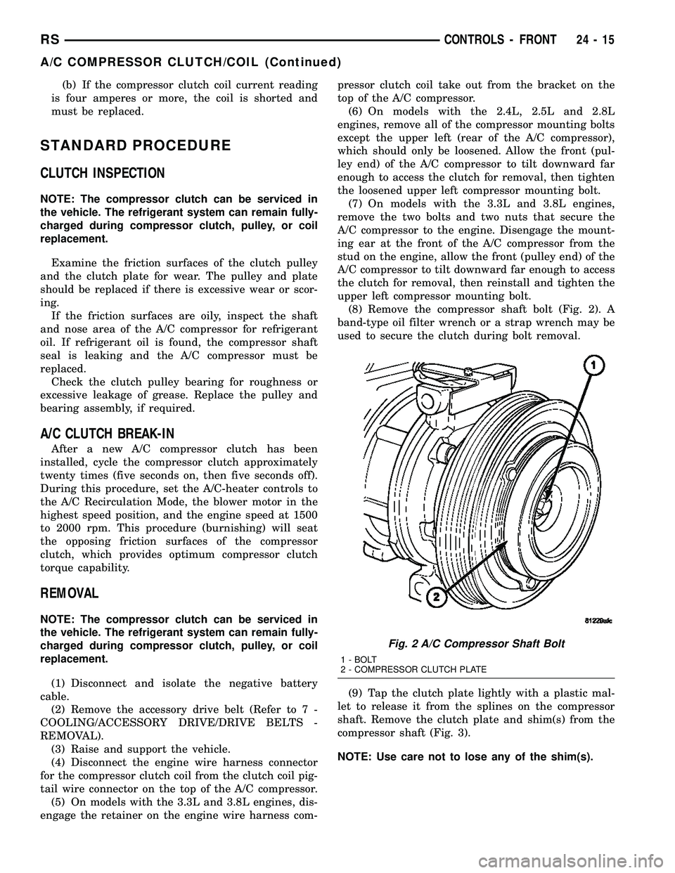
(8) Remove the compressor shaft bolt (Fig. 2). A
band-type oil filter wrench or a strap wrench may be
used to secure the clutch during bolt removal.
(9) Tap the clutch plate lightly with a plastic mal-
let to release it from the splines on the compressor
shaft. Remove the clutch plate and shim(s) from the
compressor shaft (Fig. 3).
NOTE: Use care not to lose any of the shim(s).
Fig. 2 A/C Compressor Shaft Bolt
1 - BOLT
2 - COMPRESSOR CLUTCH PLATE
RSCONTROLS - FRONT24-15
A/C COMPRESSOR CLUTCH/COIL (Continued)
Page 2168 of 2339
compressor. The bevel side of the snap ring must face
outward and both snap ring eyelets must be oriented
to the right or the left of the clutch coil dowel pin
location on the A/C compressor. Be certain that the
snap ring is fully and properly seated in the groove.
CAUTION: If the snap ring is not fully seated in the
groove it will vibrate out, resulting in a clutch fail-
ure and severe damage to the compressor front
cover.
(3) Install and securely tighten the screw that
secures the clutch coil pigtail wire connector bracket
and ground clip to the top of the compressor housing.
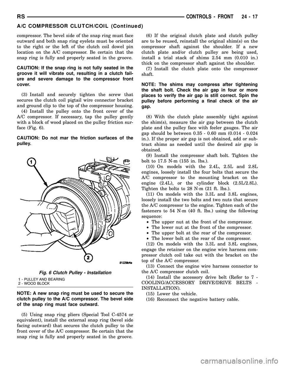
(4) Install the pulley onto the front cover of the
A/C compressor. If necessary, tap the pulley gently
with a block of wood placed on the pulley friction sur-
face (Fig. 6).
CAUTION: Do not mar the friction surfaces of the
pulley.
NOTE: A new snap ring must be used to secure the
clutch pulley to the A/C compressor. The bevel side
of the snap ring must face outward.
(5) Using snap ring pliers (Special Tool C-4574 or
equivalent), install the external snap ring (bevel side
facing outward) that secures the clutch pulley to the
front cover of the A/C compressor. Be certain that the
snap ring is fully and properly seated in the groove.(6) If the original clutch plate and clutch pulley
are to be reused, reinstall the original shim(s) on the
compressor shaft against the shoulder. If a new
clutch plate and/or clutch pulley are being used,
install a trial stack of shims 2.54 mm (0.010 in.)
thick on the compressor shaft against the shoulder.
(7) Install the clutch plate onto the compressor
shaft.
NOTE: The shims may compress after tightening
the shaft bolt. Check the air gap in four or more
places to verify the air gap is still correct. Spin the
pulley before performing a final check of the air
gap.
(8) With the clutch plate assembly tight against
the shim(s), measure the air gap between the clutch
plate and the pulley face with feeler gauges. The air
gap should be between 0.35 - 0.60 mm (0.014 - 0.024
in.). If the proper air gap is not obtained, add or sub-
tract shims as needed until the desired air gap is
obtained.
(9) Install the compressor shaft bolt. Tighten the
bolt to 17.5 N´m (155 in. lbs.).
(10) On models with the 2.4L, 2.5L and 2.8L
engines, loosely install the four bolts that secure the
A/C compressor to the mounting bracket on the
engine (2.4L), or the cylinder block (2.5L/2.8L).
Tighten the bolts to 28 N´m (21 ft. lbs.).
(11) On models with the 3.3L and 3.8L engines,
loosely install the two bolts and two nuts that secure
the A/C compressor to the engine. Tighten each of the
fasteners to 54 N´m (40 ft. lbs.) using the following
sequence:
²The upper nut at the front of the compressor.
²The lower nut at the front of the compressor.
²The upper bolt at the rear of the compressor.
²The lower bolt at the rear of the compressor.
(12) On models with the 3.3L and 3.8L engines,
engage the retainer on the engine wire harness com-
pressor clutch coil take out with the bracket on the
top of the A/C compressor.
(13) Connect the engine wire harness connector to
the A/C compressor clutch coil.
(14) Install the accessory drive belt (Refer to 7 -
COOLING/ACCESSORY DRIVE/DRIVE BELTS -
INSTALLATION).
(15) Lower the vehicle.
(16) Reconnect the negative battery cable.
Fig. 6 Clutch Pulley - Installation
1 - PULLEY AND BEARING
2 - WOOD BLOCK
RSCONTROLS - FRONT24-17
A/C COMPRESSOR CLUTCH/COIL (Continued)
Page 2173 of 2339
BLEND DOOR ACTUATOR
DESCRIPTION
The blend door actuators are reversible, 12-volt
Direct Current (DC), servo motors. Models with the
single zone heater and air conditioner system have a
single blend air door, which is controlled by a single
blend door actuator. Models with the optional dual
zone front heater and air conditioner system have
dual blend air doors, which are controlled by two
blend door actuators. The single zone blend door
actuator is located on the driver's side end of the
HVAC housing, close to the middle of the distribution
housing. In the dual zone system, the same blend
door actuator used for the single zone system
becomes the passenger blend door actuator, and is
mechanically connected to only the passenger side
blend air door. In the dual zone system, a second sep-
arate blend door actuator is also located on the
driver side end of the HVAC housing, close to the
middle of the distribution housing, and is mechani-
cally connected to only the driver's side blend air
door.
The blend door actuators are interchangeable with
each other, as well as with the actuators for the
mode door and the recirculation air door. Each actua-
tor is contained within an identical black molded
plastic housing with an integral wire connector
receptacle. Two integral mounting tabs allow the
actuator to be secured with two screws to the distri-
bution housing. Each actuator also has an identical
output shaft with splines that connects it to the link-
age that drives the proper blend air door. The blend
door actuators do not require mechanical indexing to
the blend door linkage, as they are electronically cal-
ibrated by the heater-A/C control module.
OPERATION
The blend door actuators are connected to the A/C-
heater control through the vehicle electrical system
by a dedicated two-wire lead and connector of the
HVAC wire harness. The blend door actuator(s) can
move the blend-air door(s) in two directions. When
the A/C-heater control pulls the voltage on one side
of the motor connection high and the other connec-
tion low, the blend-air door will move in one direc-
tion. When the A/C-heater control reverses the
polarity of the voltage to the motor, the blend-air
door moves in the opposite direction.
When the A/C-heater control makes the voltage to
both connections high or both connections low, the
blend-air door stops and will not move. The A/C-
heater control uses a feedback signal positioning sys-
tem to monitor the operation and relative position of
the blend door actuator(s) and the blend-air door(s).
The A/C-heater control learns the blend-air door stoppositions during the calibration procedure and will
store a diagnostic trouble code (DTC) for any prob-
lems it detects in the blend door actuator circuits.
The blend door actuators are diagnosed using a
scan tool (Refer to 24 - HEATING & AIR CONDI-
TIONING - DIAGNOSIS AND TESTING and to 24 -
HVAC Electrical Diagnostics for more information).
The blend door actuators cannot be adjusted or
repaired and, if faulty or damaged, they must be
replaced.
REMOVAL
WARNING: ON VEHICLES EQUIPPED WITH AIR-
BAGS, DISABLE THE AIRBAG SYSTEM BEFORE
ATTEMPTING ANY STEERING WHEEL, STEERING
COLUMN, OR INSTRUMENT PANEL COMPONENT
DIAGNOSIS OR SERVICE. DISCONNECT AND ISO-
LATE THE BATTERY NEGATIVE (GROUND) CABLE,
THEN WAIT TWO MINUTES FOR THE AIRBAG SYS-
TEM CAPACITOR TO DISCHARGE BEFORE PER-
FORMING FURTHER DIAGNOSIS OR SERVICE. THIS
IS THE ONLY SURE WAY TO DISABLE THE AIRBAG
SYSTEM. FAILURE TO TAKE THE PROPER PRE-
CAUTIONS COULD RESULT IN ACCIDENTAL AIR-
BAG DEPLOYMENT AND POSSIBLE PERSONAL
INJURY.
NOTE: The single zone heating and air conditioning
system is equipped with a single blend door actua-
tor. The dual zone system has two blend door
actuators, one for the driver side blend air door and
one for the passenger side blend air door. The
same service procedures can be used for each of
these actuators.
(1) Disconnect and isolate the battery negative
cable.
(2) Remove the silencer from beneath the driver
side end of the instrument panel. (Refer to 23 -
BODY/INSTRUMENT PANEL/INSTRUMENT
PANEL SILENCER - REMOVAL).
(3) Disconnect the wire harness connector from the
blend door actuator(s) (Fig. 11).
(4) Remove the two screws that secure the blend
door actuator to the distribution housing.
(5) Remove the blend door actuator.
INSTALLATION
(1) Position the blend door actuator onto the distri-
bution housing. If necessary, rotate the actuator
slightly to align the splines on the actuator output
shaft with those in the blend air door linkage.
(2) Install the two screws that secure the blend
door actuator to the housing. Tighten the screws to 2
N´m (17 in. lbs.).
24 - 22 CONTROLS - FRONTRS