ECO mode CHRYSLER VOYAGER 2005 Owner's Guide
[x] Cancel search | Manufacturer: CHRYSLER, Model Year: 2005, Model line: VOYAGER, Model: CHRYSLER VOYAGER 2005Pages: 2339, PDF Size: 59.69 MB
Page 547 of 2339
OPERATION
FRONT WIPER/WASHER SYSTEM
The windshield washer circuit is protected by a 15
amp Cartridge Fuse located in the IPM. The wiper
motor has permanent magnetic fields. The speeds are
determined by current flow to the appropriate set of
brushes inside the motor. The current flow is con-
trolled by the multi-function switch. The high speed/
low speed relays are located in the IPM. The speed
sensitive intermittent wiper is controlled by the Body
Control Module (BCM). The intermittent mode, with
the vehicle traveling greater than 10.4 mph, has a
range of 0.5 to 18 seconds. With the vehicle traveling
less than 10.4 mph, the time delay doubles to a
range of 1 to 36 seconds. The wiper arms will park at
the base of the windshield just above the cowl cover
after the wiper switch is turned OFF.
The windshield wiper motor and linkage is located
in an integral wiper unit at the rear of the engine
compartment. The wiper unit must be removed to
gain access to the wiper motor.
The front and rear washer systems share the same
washer pump motor.
REAR WIPER/WASHER SYSTEM
When rear wiper operation is required, the BCM
will provide ignition ON voltage to the rear wiper
motor (Export and ATC equipped vehicles only).
When the wiper switch is turned OFF, the BCM pro-
vides circuit ground to operate the motor until the
wipe cycle is complete and the wiper arm returns to
the base of the rear window.
Switch only offers an intermittent rear wiper
mode. The wiper motor will cycle every 7 seconds.
The intermittent delay time is also adjusted based
upon vehicle speed. With the vehicle traveling
greater than 50 mph, the cycle changes to every 5
seconds.
When rear washer is requested by depressing and
holding down the switch, the BCM then provides a
ground for the washer motor. Until the switch is
released, the motor will be in a continuous wipe
mode, then return to an intermittent wipe mode.
DIAGNOSIS AND TESTING
DIAGNOSIS AND TESTING - FRONT WIPER
SYSTEM
The windshield wiper system operates in several
modes:
²Low and high speed normal wipe
²Speed sensitive intermittent wipe
²Wipe after wash
²Park (switch OFF)The windshield wiper circuits are continuously
monitored and controlled by the Body Control Mod-
ule (BCM). If a problem occurs in the electronic com-
ponents, wiring, switch (except integral motor park
switch) and wiper motor a Diagnostic Trouble Code
(DTC) will be stored in the BCM memory. DTC's can
be retrieved using a DRB IIItscan tool. Refer to the
proper Body Diagnostic Procedures manual for DTC
descriptions and retrieval information.
The windshield wiper park switch and circuit is
monitored by the BCM. The park switch and circuit
can be tested using the Wiper System Diagnosis
table.
DIAGNOSIS AND TESTING - FRONT
WIPER/WASHER SWITCH
(1) Remove the multi-function switch (Refer to 8 -
ELECTRICAL/LAMPS/LIGHTING - EXTERIOR/
MULTI-FUNCTION SWITCH - REMOVAL).
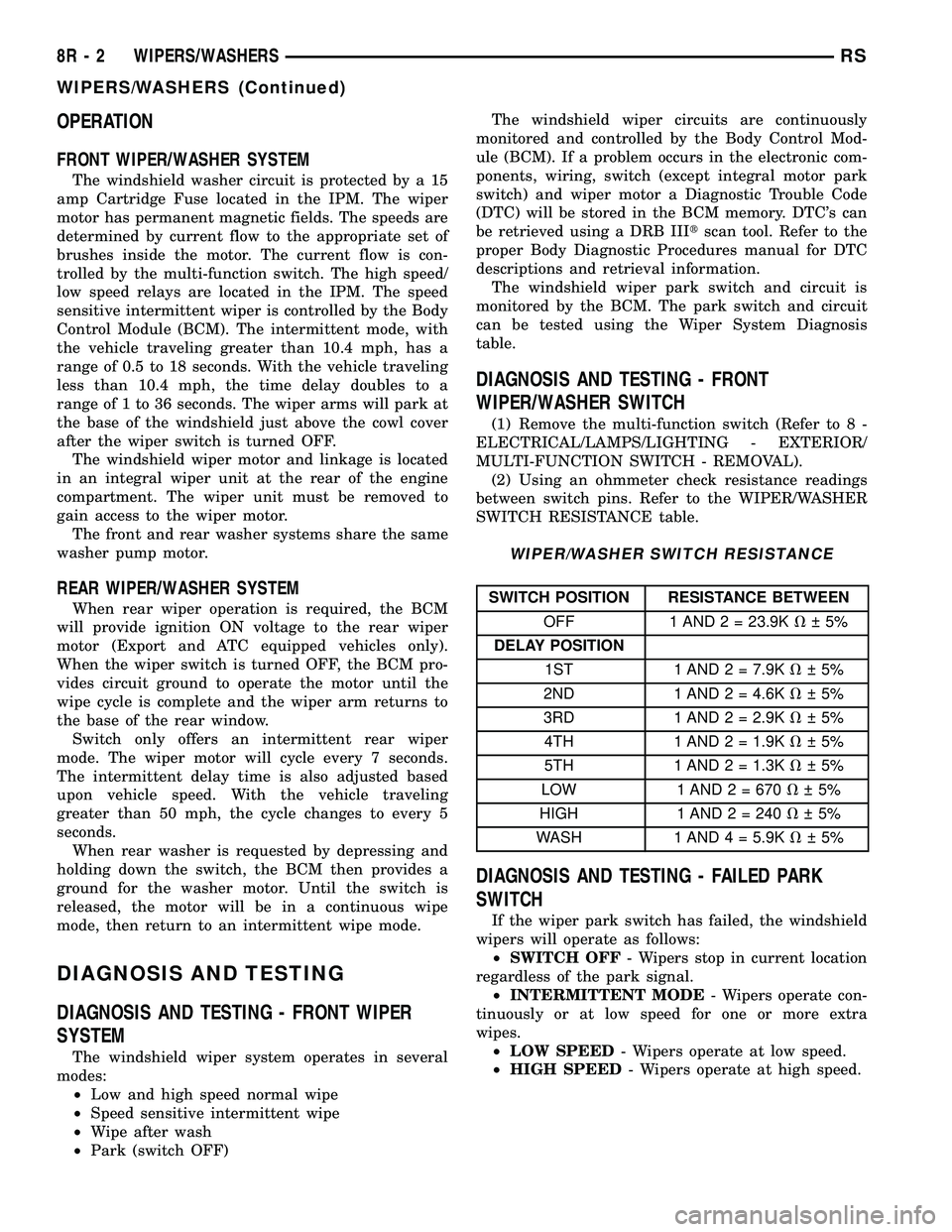
(2) Using an ohmmeter check resistance readings
between switch pins. Refer to the WIPER/WASHER
SWITCH RESISTANCE table.
WIPER/WASHER SWITCH RESISTANCE
SWITCH POSITION RESISTANCE BETWEEN
OFF 1 AND 2 = 23.9KV 5%
DELAY POSITION
1ST 1 AND 2 = 7.9KV 5%
2ND 1 AND 2 = 4.6KV 5%
3RD 1 AND 2 = 2.9KV 5%
4TH 1 AND 2 = 1.9KV 5%
5TH 1 AND 2 = 1.3KV 5%
LOW 1 AND 2 = 670V 5%
HIGH 1 AND2=240V 5%
WASH 1 AND 4 = 5.9KV 5%
DIAGNOSIS AND TESTING - FAILED PARK
SWITCH
If the wiper park switch has failed, the windshield
wipers will operate as follows:
²SWITCH OFF- Wipers stop in current location
regardless of the park signal.
²INTERMITTENT MODE- Wipers operate con-
tinuously or at low speed for one or more extra
wipes.
²LOW SPEED- Wipers operate at low speed.
²HIGH SPEED- Wipers operate at high speed.
8R - 2 WIPERS/WASHERSRS
WIPERS/WASHERS (Continued)
Page 556 of 2339
OPERATION
When rear wiper operation is required, the BCM
will provide ignition ON voltage to the rear wiper
motor. When the wiper switch is turned OFF, the
BCM provides circuit ground to operate the motor
until the wipe cycle is complete and the wiper arm
returns to the base of the rear window.
The rear wiper/washer switch only offers an inter-
mittent rear wiper mode. The wiper motor will cycle
every 7 seconds. The intermittent delay time is also
adjusted based upon vehicle speed. With the vehicle
traveling greater than 50 mph, the cycle changes to
every 5 seconds.
When rear washer is requested by depressing and
holding down the switch, the BCM then provides a
ground for the rear washer motor. Until the switch is
released, the motor will be in a continuous wipe
mode, then return to an intermittent wipe mode.
WASHER FLUID LEVEL
SWITCH
REMOVAL
(1) Disconnect and isolate the battery negative
cable.
(2) Hoist and support vehicle on hoist or jack
stands.
(3) If necessary, remove the right front wheel and
tire assembly (Refer to 22 - TIRES/WHEELS -
REMOVAL).
(4) Disconnect the right front wheelhouse splash
shield and move aside (Refer to 23 - BODY/EXTERI-
OR/WHEELHOUSE SPLASH SHIELD - REMOVAL).
(5) Drain washer fluid from the reservoir and into
a suitable clean container. This can be done by dis-connecting the windshield washer hose from the
front (outboard) washer pump port allowing the
washer fluid to drain into a container through a tem-
porary jumper hose connected to the front washer
pump.
(6) Disconnect the electrical body harness connec-
tor to the the fluid level sensor. Slide the red lock on
the connector to the release position, then, depress
the black tab and pull the connector off the sensor.
(7) Remove the sensor from reservoir by using a
side foot to gently pry the sensor from the body of
the reservoir. Do not damage the reservoir/sensor
sealing surface or puncture reservoir during removal.
CAUTION: To avoid damage to the sensor, assure
the reservoir is in an upright position before remov-
ing the sensor from the reservoir. Do not rotate the
sensor during removal.
INSTALLATION
(1) Use a new grommet when installing a new sen-
sor assembly.
(2) Assure that the flat of the sensor is aligned
under the ridge of the reservoir and that the sensor
connector is facing down in the fully seated position.
This will allow for proper operation of the sensor
float switch.
(3) Connect the electrical body harness connectors
to the fluid level sensor. Slide the red lock on the
connector to the closed or locked position.
(4) Assure that washer hose is properly routed to
prevent pinching and possible inoperative washers.
(5) Connect the left right front wheelhouse splash
shield and move aside (Refer to 23 - BODY/EXTERI-
OR/WHEELHOUSE SPLASH SHIELD - INSTALLA-
TION).
(6) Install the right front wheel and tire assembly
(Refer to 22 - TIRES/WHEELS - INSTALLATION).
(7) lower vehicle from hoist or jack stands.
(8) Connect the battery negative cable.
(9) Verify system operation.
WASHER HOSES
REMOVAL
(1) Remove washer reservoir from vehicle (Refer to
8 - ELECTRICAL/WIPERS/WASHERS/WASHER
RESERVOIR - REMOVAL).
(2) Disconnect washer hose front the reservoir cav-
ity.
(3) Disconnect the washer hose from the reservoir
pump.
(4) Remove parts as necessary to replace washer
hose (engine compartment, interior components, etc.).
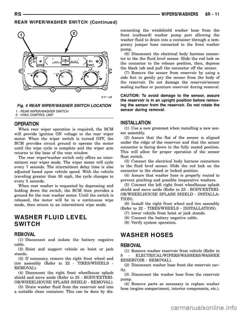
Fig. 4 REAR WIPER/WASHER SWITCH LOCATION
1 - REAR WIPER/WASHER SWITCH
2 - HVAC CONTROL UNIT
RSWIPERS/WASHERS8R-11
REAR WIPER/WASHER SWITCH (Continued)
Page 560 of 2339
NAVIGATION/TELECOMMUNICATION
TABLE OF CONTENTS
page page
NAVIGATION/TELECOMMUNICATION
DESCRIPTION..........................1
OPERATION............................1
DIAGNOSIS AND TESTING
TELECOMMUNICATION.................1HANDS FREE MODULE
REMOVAL.............................3
INSTALLATION..........................3
NAVIGATION/
TELECOMMUNICATION
DESCRIPTION
TELECOMMUNICATIONS
A hands-free cellular system is an available option
on this vehicle. It uses BluetoothŸ technology to pro-
vide wireless communication between the operator's
compatible cellular telephone and the vehicle's
on-board receiver.
The system uses voice recognition technology to
control operation. The incoming voice is broadcast
through the vehicle's radio speakers, automatically
overriding any other audio signals on the speakers
when the hands-free system is in use. A microphone
in the rearview mirror picks up vehicle occupant's
voices. If a call is in progress when the ignition is
switched off, the hands-free system will continue to
operate for up to 45 seconds as part of the Accessory
Relay Delay function. Thereafter, the call can con-
tinue on the hand-held telephone.
The center console front storage compartment
includes a cellular telephone holder, but the system
will communicate with a telephone that is anywhere
within the vehicle. However, covering the hand held
phone or the hands-free phone module with a metal
object may block the signal. The system will recog-
nize up to seven telephones, each of which is given a
spoken identification by the user during the setup
process. The system includes Spanish voice recogni-
tion in addition to English.
Two buttons on the rearview mirror, identified with
ISO icons, control the system: A9phone9button turns
the system on and off; a9voice recognition9(or voice
command) button prompts the hands-free system to
listen for a voice command.
OPERATION
TELECOMMUNICATION
Two buttons on the rearview mirror, identified with
ISO icons, control the system: A9phone9button turns
the system on and off; a9voice recognition9(or voice
command) button prompts the hands-free system to
listen for a voice command. The system includes the
following features:
²Phonebook - Stores telephone numbers for later
recall by name or other verbal identification, called a
voice tag, and memory location.
²Four memory locations - Home, Work, Mobile
and Pager. A maximum of 32 unique names or voice
tags may be stored at the same time, with a different
number in each of the four memory locations.
²Voice tag dialing - Dials the number associated
with a voice tag and memory location.
²Digit dialing - Dials the telephone number by
recognizing the names of the digits as they are spo-
ken.
²Receiving calls - A voice prompt notifies the user
of an incoming call. Pressing the ªphoneº button
answers the call.
²Privacy Mode - Switches the call to the hand-
held telephone and the hands-free system and back
again using the ªvoice recognitionº (or ªvoice com-
mandº) button and a voice command, if desired.
DIAGNOSIS AND TESTING
TELECOMMUNICATION
Any diagnosis of the Telecommunication sys-
tem should begin with the use of the DRB IIIt
diagnostic tool. For information on the use of
the DRB IIIt, refer to the appropriate Diagnos-
tic Service Information.
For complete circuit diagrams, refer to the appro-
priate wiring information.
RSNAVIGATION/TELECOMMUNICATION8T-1
Page 571 of 2339
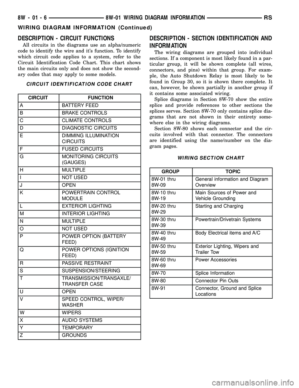
DESCRIPTION - CIRCUIT FUNCTIONS
All circuits in the diagrams use an alpha/numeric
code to identify the wire and it's function. To identify
which circuit code applies to a system, refer to the
Circuit Identification Code Chart. This chart shows
the main circuits only and does not show the second-
ary codes that may apply to some models.
CIRCUIT IDENTIFICATION CODE CHART
CIRCUIT FUNCTION
A BATTERY FEED
B BRAKE CONTROLS
C CLIMATE CONTROLS
D DIAGNOSTIC CIRCUITS
E DIMMING ILLUMINATION
CIRCUITS
F FUSED CIRCUITS
G MONITORING CIRCUITS
(GAUGES)
H MULTIPLE
I NOT USED
J OPEN
K POWERTRAIN CONTROL
MODULE
L EXTERIOR LIGHTING
M INTERIOR LIGHTING
N MULTIPLE
O NOT USED
P POWER OPTION (BATTERY
FEED)
Q POWER OPTIONS (IGNITION
FEED)
R PASSIVE RESTRAINT
S SUSPENSION/STEERING
T TRANSMISSION/TRANSAXLE/
TRANSFER CASE
U OPEN
V SPEED CONTROL, WIPER/
WASHER
W WIPERS
X AUDIO SYSTEMS
Y TEMPORARY
Z GROUNDS
DESCRIPTION - SECTION IDENTIFICATION AND
INFORMATION
The wiring diagrams are grouped into individual
sections. If a component is most likely found in a par-
ticular group, it will be shown complete (all wires,
connectors, and pins) within that group. For exam-
ple, the Auto Shutdown Relay is most likely to be
found in Group 30, so it is shown there complete. It
can, however, be shown partially in another group if
it contains some associated wiring.
Splice diagrams in Section 8W-70 show the entire
splice and provide references to other sections the
splices serves. Section 8W-70 only contains splice dia-
grams that are not shown in their entirety some-
where else in the wiring diagrams.
Section 8W-80 shows each connector and the cir-
cuits involved with that connector. The connectors
are identified using the name/number on the dia-
gram pages.
WIRING SECTION CHART
GROUP TOPIC
8W-01 thru
8W-09General information and Diagram
Overview
8W-10 thru
8W-19Main Sources of Power and
Vehicle Grounding
8W-20 thru
8W-29Starting and Charging
8W-30 thru
8W-39Powertrain/Drivetrain Systems
8W-40 thru
8W-49Body Electrical items and A/C
8W-50 thru
8W-59Exterior Lighting, Wipers and
Trailer Tow
8W-60 thru
8W-69Power Accessories
8W-70 Splice Information
8W-80 Connector Pin Outs
8W-91 Connector, Ground and Splice
Locations
8W - 01 - 6 8W-01 WIRING DIAGRAM INFORMATIONRS
WIRING DIAGRAM INFORMATION (Continued)
Page 1176 of 2339
(5) Connect the negative and positive battery
cables.
(6) Using a scan tool, check for any stored diagnos-
tic trouble codes. Ensure that all vehicle options are
operational.
IOD FUSE
DESCRIPTION
All vehicles are equipped with an Ignition-Off
Draw (IOD) fuse that is removed from its normal
cavity in the Integrated Power Module (IPM) when
the vehicle is shipped from the factory. Dealer per-
sonnel are to remove the IOD fuse from the storage
location and install it into the IPM fuse cavity
marked IOD as part of the preparation procedures
performed just prior to new vehicle delivery.
The IOD fuse is a 20 ampere blade-type mini fuse
and, when removed, it is stored in a fuse cavity adja-
cent to the washer fuse within the IPM.
OPERATION
The term ignition-off draw (IOD) identifies a nor-
mal condition where power is being drained from the
battery with the ignition switch in the Off position.
The IOD fuse feeds the memory and sleep mode func-
tions for some of the electronic modules in the vehicle
as well as various other accessories that require bat-
tery current when the ignition switch is in the Off
position, including the clock. The only reason the
IOD fuse is removed is to reduce the normal IOD of
the vehicle electrical system during new vehicle
transportation and pre-delivery storage to reduce
battery depletion, while still allowing vehicle opera-
tion so that the vehicle can be loaded, unloaded and
moved as needed by both vehicle transportation com-
pany and dealer personnel.
The IOD fuse is removed from the Integrated
Power Module (IPM) fuse cavity when the vehicle is
shipped from the assembly plant. Dealer personnel
must install the IOD fuse when the vehicle is being
prepared for delivery in order to restore full electrical
system operation. Once the vehicle is prepared for
delivery, the IOD function of this fuse becomes trans-
parent and the fuse that has been assigned the IOD
designation becomes only another Fused B(+) circuit
fuse. The IOD fuse serves no useful purpose to the
dealer technician in the service or diagnosis of any
vehicle system or condition, other than the same pur-
pose as that of any other standard circuit protection
device.
The IOD fuse can be used by the vehicle owner as
a convenient means of reducing battery depletion
when a vehicle is to be stored for periods not to
exceed approximately thirty days. However, it mustbe remembered that removing the IOD fuse will not
eliminate IOD, but only reduce this normal condition.
If a vehicle will be stored for more than thirty days,
the battery negative cable should be disconnected to
eliminate normal IOD; and, the battery should be
tested and recharged at regular intervals during the
vehicle storage period to prevent the battery from
becoming discharged or damaged.
POWER OUTLET
DESCRIPTION
Two power outlets are installed in the instrument
panel center lower bezel. Two additional power out-
lets are incorporated into the left rear C-pillar and
the center console (if equipped). The power outlets
bases are secured by a snap fit. A hinged plug flips
closed to conceal and protect the power outlet base
when not in use.
OPERATION
The power outlet base or receptacle shell is con-
nected to ground, and an insulated contact in the
bottom of the shell is connected to battery current.
The power outlet on the instrument panel marked
with a battery receives battery voltage from a fuse in
the Integrated Power Module (IPM) at all times. The
other power outlet on the instrument panel marked
with a key receives battery voltage only when the
key is in the on position.
The power outlet located in the center console
receives battery voltage all the time when positioned
between thefront seatsand key-on voltage when
positioned between therear seats. The power outlet
located on the C-pillar receives battery voltage only
when the key is in the ON position.
DIAGNOSIS AND TESTING
DIAGNOSIS & TESTING - POWER OUTLET
WARNING: ON VEHICLES EQUIPPED WITH AIR-
BAGS, REFER TO RESTRAINTS BEFORE ATTEMPT-
ING ANY STEERING WHEEL, STEERING COLUMN,
SEAT OR INSTRUMENT PANEL COMPONENT DIAG-
NOSIS OR SERVICE. FAILURE TO TAKE THE
PROPER PRECAUTIONS COULD RESULT IN ACCI-
DENTAL AIRBAG DEPLOYMENT AND POSSIBLE
PERSONAL INJURY.
(1) Check the fused B(+) fuse in the Integrated
Power Module (IPM). If OK, go to Step 2. If not OK,
repair the shorted circuit or component as required
and replace the faulty fuse.
RS8W-97 POWER DISTRIBUTION SYSTEM8W-97-3
INTEGRATED POWER MODULE (Continued)
Page 1377 of 2339
INSTALLATION - 3.3/3.8L
(1) Ensure injector holes are clean. Replace
O-rings if damaged.
(2) Lubricate injector O-rings with a drop of clean
engine oil to ease installation.
(3) Put the tip of each injector into their ports.
Push the assembly into place until the injectors are
seated in the ports.
(4) Install the fuel rail mounting bolts. Tighten
bolts to 22 N´m (200 in. lbs.) torque.
(5) Remove covering on lower intake manifold and
clean surface.
(6) Install the Upper Intake Manifold, refer to
Engine/Manifolds/Upper Intake for more information.
(7) Install fuel hose quick connector fitting to chas-
sis tubes.Refer to Fuel Hoses, Clamps and
Quick Connect Fittings in this Section.Push the
fitting onto the chassis tube until it clicks into place.
Pull on the fitting to ensure complete insertion.
(8) Connect negative cable to battery.
(9) Use the DRBIIItscan tool to pressurize the
fuel system. Check for leaks.
FUEL TANK
DESCRIPTION
The fuel tank is constructed of a plastic material.
Its main functions are for fuel storage and for place-
ment of the fuel pump module. The tank is made
from High density Polyethylene (HDPE) material.If
equipped with ORVR (Onboard Refueling Vapor
Recovery) it has been added to the fuel tank to con-
trol refueling vapor emissions.
OPERATION
All models pass a full 360 degree rollover test
without fuel leakage. To accomplish this, fuel and
vapor flow controls are required for all fuel tank con-
nections.
All models are equipped with either one or two
check valves mounted into the top of the fuel tank (or
pump module).
An evaporation control system is connected to the
check valve(s)/control valve(Refer to 25 - EMIS-
SIONS CONTROL/EVAPORATIVE EMISSIONS/
ORVR - OPERATION) to reduce emissions of fuel
vapors into the atmosphere, when the tank is vented
due to vapor expansion in the tank. When fuel evap-
orates from the fuel tank, vapors pass through vent
hoses or tubes to a charcoal canister where they are
temporarily held. When the engine is running, the
vapors are drawn into the intake manifold. In addi-
tion, fuel vapors produced during vehicle refueling
are allowed to pass through the vent hoses/tubes to
the charcoal canister(s) for temporary storage (priorto being drawn into the intake manifold). All models
are equipped with a self-diagnosing system using a
Leak Detection Pump (LDP) or Natural Vacuum
Leak Detection (NVLD). Refer to the Emission Con-
trol System for additional information.
INLET CHECK VALVE
All vehicles have an inlet check valve on the inside
of the fuel tank at the filler inlet
The valve prevents fuel from splashing back on
customer during vehicle refueling. The valve is a
non-serviceable item.
REMOVAL
REMOVAL
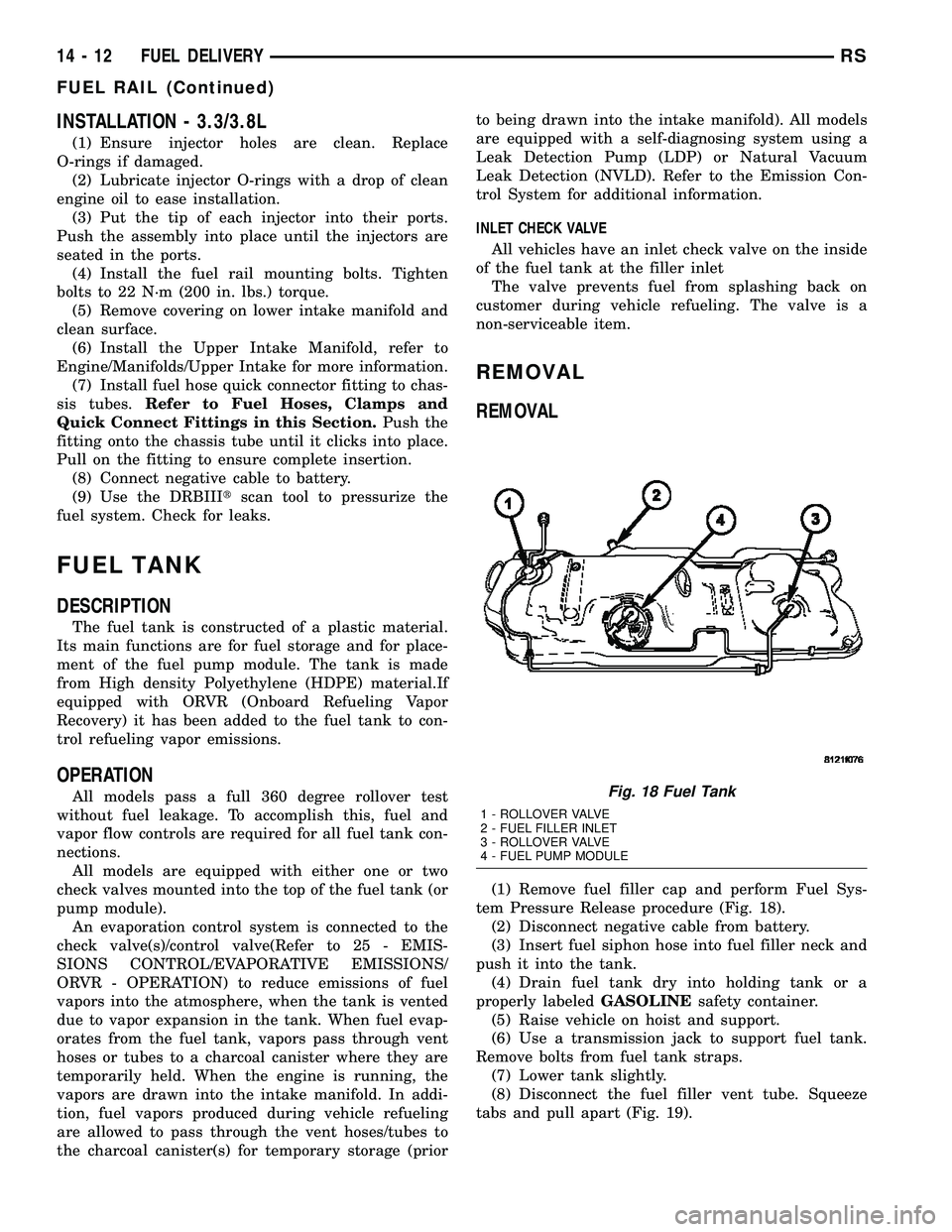
(1) Remove fuel filler cap and perform Fuel Sys-
tem Pressure Release procedure (Fig. 18).
(2) Disconnect negative cable from battery.
(3) Insert fuel siphon hose into fuel filler neck and
push it into the tank.
(4) Drain fuel tank dry into holding tank or a
properly labeledGASOLINEsafety container.
(5) Raise vehicle on hoist and support.
(6) Use a transmission jack to support fuel tank.
Remove bolts from fuel tank straps.
(7) Lower tank slightly.
(8) Disconnect the fuel filler vent tube. Squeeze
tabs and pull apart (Fig. 19).
Fig. 18 Fuel Tank
1 - ROLLOVER VALVE
2 - FUEL FILLER INLET
3 - ROLLOVER VALVE
4 - FUEL PUMP MODULE
14 - 12 FUEL DELIVERYRS
FUEL RAIL (Continued)
Page 1387 of 2339

FUEL INJECTION
OPERATION
OPERATION - INJECTION SYSTEM
All engines used in this section have a sequential
Multi-Port Electronic Fuel Injection system. The MPI
system is computer regulated and provides precise
air/fuel ratios for all driving conditions. The Power-
train Control Module (PCM) operates the fuel injec-
tion system.
The PCM regulates:
²Ignition timing
²Air/fuel ratio
²Emission control devices
²Cooling fan
²Charging system
²Idle speed
²Vehicle speed control
Various sensors provide the inputs necessary for
the PCM to correctly operate these systems. In addi-
tion to the sensors, various switches also provide
inputs to the PCM.
The PCM can adapt its programming to meet
changing operating conditions.
Fuel is injected into the intake port above the
intake valve in precise metered amounts through
electrically operated injectors. The PCM fires the
injectors in a specific sequence. Under most operat-
ing conditions, the PCM maintains an air fuel ratio
of 14.7 parts air to 1 part fuel by constantly adjust-
ing injector pulse width. Injector pulse width is the
length of time the injector is open.
The PCM adjusts injector pulse width by opening
and closing the ground path to the injector. Engine
RPM (speed) and manifold absolute pressure (air
density) are theprimaryinputs that determine
injector pulse width.
OPERATION - MODES OF OPERATION
As input signals to the PCM change, the PCM
adjusts its response to output devices. For example,
the PCM must calculate a different injector pulse
width and ignition timing for idle than it does for
Wide Open Throttle (WOT). There are several differ-
ent modes of operation that determine how the PCM
responds to the various input signals.
There are two different areas of operation, OPEN
LOOP and CLOSED LOOP.
During OPEN LOOP modes the PCM receives
input signals and responds according to preset PCM
programming. Inputs from the upstream and down-
stream heated oxygen sensors are not monitored dur-
ing OPEN LOOP modes, except for heated oxygensensor diagnostics (they are checked for shorted con-
ditions at all times).
During CLOSED LOOP modes the PCM monitors
the inputs from the upstream and downstream
heated oxygen sensors. The upstream heated oxygen
sensor input tells the PCM if the calculated injector
pulse width resulted in the ideal air-fuel ratio of 14.7
to one. By monitoring the exhaust oxygen content
through the upstream heated oxygen sensor, the
PCM can fine tune injector pulse width. Fine tuning
injector pulse width allows the PCM to achieve opti-
mum fuel economy combined with low emissions.
For the PCM to enter CLOSED LOOP operation,
the following must occur:
(1) Engine coolant temperature must be over 35ÉF.
²If the coolant is over 35ÉF the PCM will wait 38
seconds.
²If the coolant is over 50ÉF the PCM will wait 15
seconds.
²If the coolant is over 167ÉF the PCM will wait 3
seconds.
(2) For other temperatures the PCM will interpo-
late the correct waiting time.
(3) O2 sensor must read either greater than 0.745
volts or less than 0.29 volt.
(4) The multi-port fuel injection systems has the
following modes of operation:
²Ignition switch ON (Zero RPM)
²Engine start-up
²Engine warm-up
²Cruise
²Idle
²Acceleration
²Deceleration
²Wide Open Throttle
²Ignition switch OFF
(5) The engine start-up (crank), engine warm-up,
deceleration with fuel shutoff and wide open throttle
modes are OPEN LOOP modes. Under most operat-
ing conditions, the acceleration, deceleration (with
A/C on), idle and cruise modes,with the engine at
operating temperatureare CLOSED LOOP modes.
IGNITION SWITCH ON (ZERO RPM) MODE
When the ignition switch activates the fuel injec-
tion system, the following actions occur:
²The PCM monitors the engine coolant tempera-
ture sensor and throttle position sensor input. The
PCM determines basic fuel injector pulse width from
this input.
²The PCM determines atmospheric air pressure
from the MAP sensor input to modify injector pulse
width.
When the key is in the ON position and the engine
is not running (zero rpm), the Auto Shutdown (ASD)
and fuel pump relays de-energize after approximately
14 - 22 FUEL INJECTIONRS
Page 1388 of 2339

1 second. Therefore, battery voltage is not supplied to
the fuel pump, ignition coil, fuel injectors and heated
oxygen sensors.
ENGINE START-UP MODE
This is an OPEN LOOP mode. If the vehicle is in
park or neutral (automatic transaxles) or the clutch
pedal is depressed (manual transaxles) the ignition
switch energizes the starter relay when the engine is
not running. The following actions occur when the
starter motor is engaged.
²If the PCM receives the camshaft position sensor
and crankshaft position sensor signals, it energizes
the Auto Shutdown (ASD) relay and fuel pump relay.
If the PCM does not receive both signals within
approximately one second, it will not energize the
ASD relay and fuel pump relay. The ASD and fuel
pump relays supply battery voltage to the fuel pump,
fuel injectors, ignition coil, (EGR solenoid and PCV
heater if equipped) and heated oxygen sensors.
²The PCM energizes the injectors (on the 69É
degree falling edge) for a calculated pulse width until
it determines crankshaft position from the camshaft
position sensor and crankshaft position sensor sig-
nals. The PCM determines crankshaft position within
1 engine revolution.
²After determining crankshaft position, the PCM
begins energizing the injectors in sequence. It adjusts
injector pulse width and controls injector synchroni-
zation by turning the individual ground paths to the
injectors On and Off.
²When the engine idles within 64 RPM of its
target RPM, the PCM compares current MAP sensor
value with the atmospheric pressure value received
during the Ignition Switch On (zero RPM) mode.
Once the ASD and fuel pump relays have been
energized, the PCM determines injector pulse width
based on the following:
²MAP
²Engine RPM
²Battery voltage
²Engine coolant temperature
²Inlet/Intake air temperature (IAT)
²Throttle position
²The number of engine revolutions since cranking
was initiated
During Start-up the PCM maintains ignition tim-
ing at 9É BTDC.
ENGINE WARM-UP MODE
This is an OPEN LOOP mode. The following inputs
are received by the PCM:
²Manifold Absolute Pressure (MAP)
²Crankshaft position (engine speed)
²Engine coolant temperature
²Inlet/Intake air temperature (IAT)²Camshaft position
²Knock sensor
²Throttle position
²A/C switch status
²Battery voltage
²Vehicle speed
²Speed control
²O2 sensors
The PCM adjusts injector pulse width and controls
injector synchronization by turning the individual
ground paths to the injectors On and Off.
The PCM adjusts ignition timing and engine idle
speed. Engine idle speed is adjusted through the idle
air control motor.
CRUISE OR IDLE MODE
When the engine is at operating temperature this
is a CLOSED LOOP mode. During cruising or idle
the following inputs are received by the PCM:
²Manifold absolute pressure
²Crankshaft position (engine speed)
²Inlet/Intake air temperature
²Engine coolant temperature
²Camshaft position
²Knock sensor
²Throttle position
²Exhaust gas oxygen content (O2 sensors)
²A/C switch status
²Battery voltage
²Vehicle speed
The PCM adjusts injector pulse width and controls
injector synchronization by turning the individual
ground paths to the injectors On and Off.
The PCM adjusts engine idle speed and ignition
timing. The PCM adjusts the air/fuel ratio according
to the oxygen content in the exhaust gas (measured
by the upstream and downstream heated oxygen sen-
sor).
The PCM monitors for engine misfire. During
active misfire and depending on the severity, the
PCM either continuously illuminates or flashes the
malfunction indicator lamp (Check Engine light on
instrument panel). Also, the PCM stores an engine
misfire DTC in memory, if 2nd trip with fault.
The PCM performs several diagnostic routines.
They include:
²Oxygen sensor monitor
²Downstream heated oxygen sensor diagnostics
during open loop operation (except for shorted)
²Fuel system monitor
²EGR monitor (if equipped)
²Purge system monitor
²Catalyst efficiency monitor
²All inputs monitored for proper voltage range,
rationality.
RSFUEL INJECTION14-23
FUEL INJECTION (Continued)
Page 1389 of 2339

²All monitored components (refer to the Emission
section for On-Board Diagnostics).
The PCM compares the upstream and downstream
heated oxygen sensor inputs to measure catalytic
convertor efficiency. If the catalyst efficiency drops
below the minimum acceptable percentage, the PCM
stores a diagnostic trouble code in memory, after 2
trips.
During certain idle conditions, the PCM may enter
a variable idle speed strategy. During variable idle
speed strategy the PCM adjusts engine speed based
on the following inputs.
²A/C status
²Battery voltage
²Battery temperature or Calculated Battery Tem-
perature
²Engine coolant temperature
²Engine run time
²Inlet/Intake air temperature
²Vehicle mileage
ACCELERATION MODE
This is a CLOSED LOOP mode. The PCM recog-
nizes an abrupt increase in Throttle Position sensor
output voltage or MAP sensor output voltage as a
demand for increased engine output and vehicle
acceleration. The PCM increases injector pulse width
in response to increased fuel demand.
²Wide Open Throttle-open loop
DECELERATION MODE
This is a CLOSED LOOP mode. During decelera-
tion the following inputs are received by the PCM:
²A/C status
²Battery voltage
²Inlet/Intake air temperature
²Engine coolant temperature
²Crankshaft position (engine speed)
²Exhaust gas oxygen content (upstream heated
oxygen sensor)
²Knock sensor
²Manifold absolute pressure
²Throttle position sensor
²IAC motor (solenoid) control changes in response
to MAP sensor feedback
The PCM may receive a closed throttle input from
the Throttle Position Sensor (TPS) when it senses an
abrupt decrease in manifold pressure. This indicates
a hard deceleration (Open Loop). In response, the
PCM may momentarily turn off the injectors. This
helps improve fuel economy, emissions and engine
braking.
WIDE-OPEN-THROTTLE MODE
This is an OPEN LOOP mode. During wide-open-
throttle operation, the following inputs are used by
the PCM:
²Inlet/Intake air temperature
²Engine coolant temperature
²Engine speed
²Knock sensor
²Manifold absolute pressure
²Throttle position
When the PCM senses a wide-open-throttle condi-
tion through the Throttle Position Sensor (TPS) it de-
energizes the A/C compressor clutch relay. This
disables the air conditioning system and disables
EGR (if equipped).
The PCM adjusts injector pulse width to supply a
predetermined amount of additional fuel, based on
MAP and RPM.
IGNITION SWITCH OFF MODE
When the operator turns the ignition switch to the
OFF position, the following occurs:
²All outputs are turned off, unless 02 Heater
Monitor test is being run. Refer to the Emission sec-
tion for On-Board Diagnostics.
²No inputs are monitored except for the heated
oxygen sensors. The PCM monitors the heating ele-
ments in the oxygen sensors and then shuts down.
FUEL CORRECTION or ADAPTIVE MEMORIES
DESCRIPTION
In Open Loop, the PCM changes pulse width with-
out feedback from the O2 Sensors. Once the engine
warms up to approximately 30 to 35É F, the PCM
goes into closed loopShort Term Correctionand
utilizes feedback from the O2 Sensors. Closed loop
Long Term Adaptive Memoryis maintained above
170É to 190É F unless the PCM senses wide open
throttle. At that time the PCM returns to Open Loop
operation.
OPERATION
Short Term
The first fuel correction program that begins func-
tioning is the short term fuel correction. This system
corrects fuel delivery in direct proportion to the read-
ings from the Upstream O2 Sensor.
The PCM monitors the air/fuel ratio by using the
input voltage from the O2 Sensor. When the voltage
reaches its preset high or low limit, the PCM begins
to add or remove fuel until the sensor reaches its
switch point. The short term corrections then begin.
The PCM makes a series of quick changes in the
injector pulse-width until the O2 Sensor reaches its
14 - 24 FUEL INJECTIONRS
FUEL INJECTION (Continued)
Page 1563 of 2339

(15) Install input clutch assembly to the Input
Clutch Pressure Fixture±Tool 8391 (Fig. 233).
(16) Set up dial indicator on the UD clutch pack as
shown in (Fig. 234).
(17) Using moderate pressure, press down and
hold (near indicator) the UD clutch pack with screw-
driver or suitable tool and zero dial indicator (Fig.
235). When releasing pressure on clutch pack, indica-
tor reading should advance 0.005±0.010.
CAUTION: Do not apply more than 30 psi (206 kPa)
to the underdrive clutch pack.
(18) Apply 30 psi (206 kPa) to the underdrive hose
on Tool 8391 and measure UD clutch clearance. Mea-
sure and record UD clutch pack measurement in four
(4) places, 90É apart.
(19) Take average of four measurements and com-
pare with UD clutch pack clearance specification.
Underdrive clutch pack clearance must be 0.94-
1.50 mm (0.037-0.059 in.).
(20) If necessary, select the proper reaction plate
to achieve specifications:
UNDERDRIVE REACTION PLATE THICKNESS
4659939AB 5.837-5.937 mm (0.230-0.234 in.)
4659940AB 6.147-6.248 mm (0.242-0.246 in.)
4659941AB 6.457-6.557 mm (0.254-0.258 in.)
Fig. 233 Input Clutch Assembly on Pressure Fixture
Tool 8391
1 - INPUT CLUTCH ASSEMBLY
2 - INPUT CLUTCH PRESSURE FIXTURE 8391
Fig. 234 Set Up Dial Indicator to Measure UD Clutch
Clearance
1 - DIAL INDICATOR
2 - UNDERDRIVE CLUTCH
Fig. 235 Press Down on UD Clutch Pack and Zero
Dial Indicator
1 - DIAL INDICATOR
2 - UNDERDRIVE CLUTCH
21 - 102 40TE AUTOMATIC TRANSAXLERS
INPUT CLUTCH ASSEMBLY (Continued)