TCM CHRYSLER VOYAGER 2005 Service Manual
[x] Cancel search | Manufacturer: CHRYSLER, Model Year: 2005, Model line: VOYAGER, Model: CHRYSLER VOYAGER 2005Pages: 2339, PDF Size: 59.69 MB
Page 288 of 2339
The BCM utilizes integrated circuitry and informa-
tion carried on the Programmable Communications
Interface (PCI) data bus network along with many
hard wired inputs to monitor many sensor and
switch inputs throughout the vehicle. In response to
those inputs, the internal circuitry and programming
of the BCM allow it to control and integrate many
electronic functions and features of the vehicle
through both hard wired outputs and the transmis-
sion of electronic message outputs to other electronic
modules in the vehicle over the PCI data bus.
OPERATION
The Body Control Module (BCM) supplies vehicle
occupants with visual and audible information and
controls various vehicle functions. To provide and
receive information, the BCM is interfaced to the
vehicle's serial bus communications network, referred
to as the Programmable Communications Interface
(PCI) bus.
This network consists of the;
²Powertrain Control Module (PCM)
²Transmission Control Module (TCM)
²Mechanical Instrument Cluster (MIC)
²Occupant Restraint Controller (ORC)
²Compass/Mini-Trip Computer (CMTC)
²Electronic Vehicle Information Center (EVIC)
²Controller Antilock Brake (CAB)
²HVAC Control Module
²Sliding Door Control Modules (driver and pas-
senger side doors)
²Power Liftgate Module (PLG)
²Audio system equipped with RAZ, RBU, RBK,
and RBB radios.
²Sentry Key Remote Entry Module (SKREEM).
²Side Impact Airbag Control Module (SIACM)²Memory Seat Module (MSM)
²Sentry Key Immobilizer Module (SKIM)
The BCM is operational when battery power is
supplied to the module.
The BCM provides the following features:
²Power Door Locks
²Automatic Door Locks
²Battery Protection - The BCM will automatically
turn off all exterior lamps after 3 minutes, and all
interior lamps after 15 minutes after the ignition is
turned off, if they are not turned off by the driver.
²Chime Control
²Compass/Mini-Trip support.
²Interior Lighting (Courtesy/Reading Lamps)
²BCM Diagnostic Reporting
²Electronic Liftgate Release (with Power Door
Locks)
²Exterior Lighting
²Headlamp Time Delay (with/without Automatic
Headlamps)
²Illuminated Entry
²Fade to Off Interior Lamps - This feature dims
the interior lighting (courtesy lamps) gradually if the
BCM does not receive any new inputs that would
cause the interior lamps to remain on.
²Pulse Width Modulated Instrument Panel Dim-
ming
²Door Lock Inhibit - This feature disables the
door lock functions if the key is in the ignition and
either front door is ajar. Pressing the Remote Keyless
Entry (RKE) lock/unlock button under these condi-
tions result in normal lock/unlock activation.
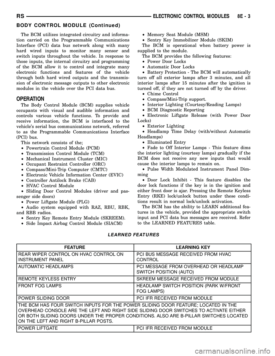
The BCM has the ability to LEARN additional fea-
tures in the vehicle, provided the appropriate switch
input and PCI data bus messages are received. Refer
to the LEARNED FEATURES table.
LEARNED FEATURES
FEATURE LEARNING KEY
REAR WIPER CONTROL ON HVAC CONTROL ON
INSTRUMENT PANELPCI BUS MESSAGE RECEIVED FROM HVAC
CONTROL
AUTOMATIC HEADLAMPS PCI MESSAGE FROM OVERHEAD OR HEADLAMP
SWITCH POSITION (AUTO)
REMOTE KEYLESS ENTRY SKREEM MESSAGE RECEIVED FROM MODULE
FRONT FOG LAMPS HEADLAMP SWITCH POSITION (PARK W/FRONT
FOG LAMPS)
POWER SLIDING DOOR PCI IFR RECEIVED FROM MODULE
THE BCM HAS FOUR SWITCH INPUTS FOR THE POWER SLIDING DOOR FEATURE; LOCATED IN THE
OVERHEAD CONSOLE ARE THE LEFT AND RIGHT SIDE SLIDING DOOR SWITCHES TO ACTIVATE EITHER
OR BOTH SLIDING DOORS UNDER THE PROPER CONDITIONS. ALSO ARE B-PILLAR SWITCHES LOCATED
ON THE LEFT AND RIGHT B-PILLAR POSTS.
POWER LIFTGATE PCI IFR RECEIVED FROM MODULE
RSELECTRONIC CONTROL MODULES8E-3
BODY CONTROL MODULE (Continued)
Page 377 of 2339
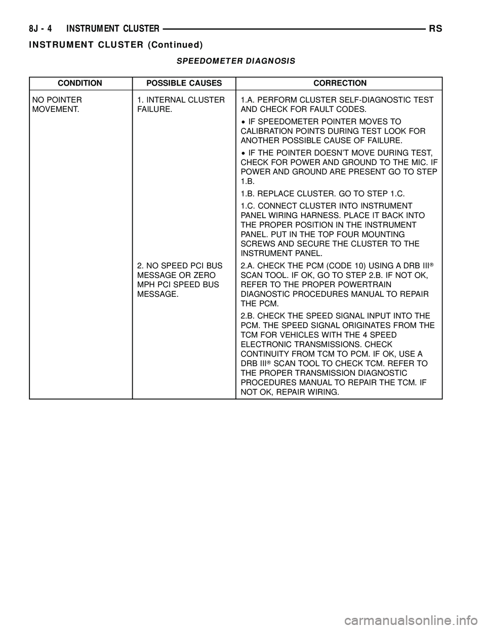
SPEEDOMETER DIAGNOSIS
CONDITION POSSIBLE CAUSES CORRECTION
NO POINTER
MOVEMENT.1. INTERNAL CLUSTER
FAILURE.1.A. PERFORM CLUSTER SELF-DIAGNOSTIC TEST
AND CHECK FOR FAULT CODES.
²IF SPEEDOMETER POINTER MOVES TO
CALIBRATION POINTS DURING TEST LOOK FOR
ANOTHER POSSIBLE CAUSE OF FAILURE.
²IF THE POINTER DOESN'T MOVE DURING TEST,
CHECK FOR POWER AND GROUND TO THE MIC. IF
POWER AND GROUND ARE PRESENT GO TO STEP
1.B.
1.B. REPLACE CLUSTER. GO TO STEP 1.C.
1.C. CONNECT CLUSTER INTO INSTRUMENT
PANEL WIRING HARNESS. PLACE IT BACK INTO
THE PROPER POSITION IN THE INSTRUMENT
PANEL. PUT IN THE TOP FOUR MOUNTING
SCREWS AND SECURE THE CLUSTER TO THE
INSTRUMENT PANEL.
2. NO SPEED PCI BUS
MESSAGE OR ZERO
MPH PCI SPEED BUS
MESSAGE.2.A. CHECK THE PCM (CODE 10) USING A DRB IIIT
SCAN TOOL. IF OK, GO TO STEP 2.B. IF NOT OK,
REFER TO THE PROPER POWERTRAIN
DIAGNOSTIC PROCEDURES MANUAL TO REPAIR
THE PCM.
2.B. CHECK THE SPEED SIGNAL INPUT INTO THE
PCM. THE SPEED SIGNAL ORIGINATES FROM THE
TCM FOR VEHICLES WITH THE 4 SPEED
ELECTRONIC TRANSMISSIONS. CHECK
CONTINUITY FROM TCM TO PCM. IF OK, USE A
DRB IIITSCAN TOOL TO CHECK TCM. REFER TO
THE PROPER TRANSMISSION DIAGNOSTIC
PROCEDURES MANUAL TO REPAIR THE TCM. IF
NOT OK, REPAIR WIRING.
8J - 4 INSTRUMENT CLUSTERRS
INSTRUMENT CLUSTER (Continued)
Page 378 of 2339
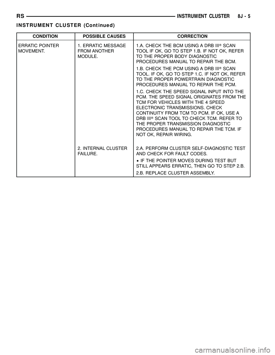
CONDITION POSSIBLE CAUSES CORRECTION
ERRATIC POINTER
MOVEMENT.1. ERRATIC MESSAGE
FROM ANOTHER
MODULE.1.A. CHECK THE BCM USING A DRB IIITSCAN
TOOL IF OK, GO TO STEP 1.B. IF NOT OK, REFER
TO THE PROPER BODY DIAGNOSTIC
PROCEDURES MANUAL TO REPAIR THE BCM.
1.B. CHECK THE PCM USING A DRB IIITSCAN
TOOL. IF OK, GO TO STEP 1.C. IF NOT OK, REFER
TO THE PROPER POWERTRAIN DIAGNOSTIC
PROCEDURES MANUAL TO REPAIR THE PCM.
1.C. CHECK THE SPEED SIGNAL INPUT INTO THE
PCM. THE SPEED SIGNAL ORIGINATES FROM THE
TCM FOR VEHICLES WITH THE 4 SPEED
ELECTRONIC TRANSMISSIONS. CHECK
CONTINUITY FROM TCM TO PCM. IF OK, USE A
DRB IIITSCAN TOOL TO CHECK TCM. REFER TO
THE PROPER TRANSMISSION DIAGNOSTIC
PROCEDURES MANUAL TO REPAIR THE TCM. IF
NOT OK, REPAIR WIRING.
2. INTERNAL CLUSTER
FAILURE.2.A. PERFORM CLUSTER SELF-DIAGNOSTIC TEST
AND CHECK FOR FAULT CODES.
²IF THE POINTER MOVES DURING TEST BUT
STILL APPEARS ERRATIC, THEN GO TO STEP 2.B.
2.B. REPLACE CLUSTER ASSEMBLY.
RSINSTRUMENT CLUSTER8J-5
INSTRUMENT CLUSTER (Continued)
Page 379 of 2339
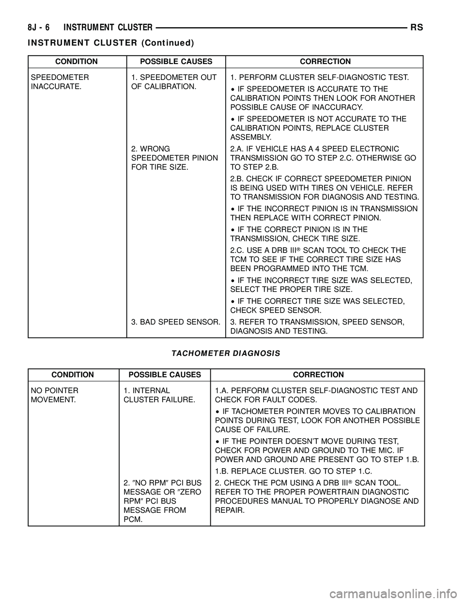
CONDITION POSSIBLE CAUSES CORRECTION
SPEEDOMETER
INACCURATE.1. SPEEDOMETER OUT
OF CALIBRATION.1. PERFORM CLUSTER SELF-DIAGNOSTIC TEST.
²IF SPEEDOMETER IS ACCURATE TO THE
CALIBRATION POINTS THEN LOOK FOR ANOTHER
POSSIBLE CAUSE OF INACCURACY.
²IF SPEEDOMETER IS NOT ACCURATE TO THE
CALIBRATION POINTS, REPLACE CLUSTER
ASSEMBLY.
2. WRONG
SPEEDOMETER PINION
FOR TIRE SIZE.2.A. IF VEHICLE HAS A 4 SPEED ELECTRONIC
TRANSMISSION GO TO STEP 2.C. OTHERWISE GO
TO STEP 2.B.
2.B. CHECK IF CORRECT SPEEDOMETER PINION
IS BEING USED WITH TIRES ON VEHICLE. REFER
TO TRANSMISSION FOR DIAGNOSIS AND TESTING.
²IF THE INCORRECT PINION IS IN TRANSMISSION
THEN REPLACE WITH CORRECT PINION.
²IF THE CORRECT PINION IS IN THE
TRANSMISSION, CHECK TIRE SIZE.
2.C. USE A DRB IIITSCAN TOOL TO CHECK THE
TCM TO SEE IF THE CORRECT TIRE SIZE HAS
BEEN PROGRAMMED INTO THE TCM.
²IF THE INCORRECT TIRE SIZE WAS SELECTED,
SELECT THE PROPER TIRE SIZE.
²IF THE CORRECT TIRE SIZE WAS SELECTED,
CHECK SPEED SENSOR.
3. BAD SPEED SENSOR. 3. REFER TO TRANSMISSION, SPEED SENSOR,
DIAGNOSIS AND TESTING.
TACHOMETER DIAGNOSIS
CONDITION POSSIBLE CAUSES CORRECTION
NO POINTER
MOVEMENT.1. INTERNAL
CLUSTER FAILURE.1.A. PERFORM CLUSTER SELF-DIAGNOSTIC TEST AND
CHECK FOR FAULT CODES.
²IF TACHOMETER POINTER MOVES TO CALIBRATION
POINTS DURING TEST, LOOK FOR ANOTHER POSSIBLE
CAUSE OF FAILURE.
²IF THE POINTER DOESN'T MOVE DURING TEST,
CHECK FOR POWER AND GROUND TO THE MIC. IF
POWER AND GROUND ARE PRESENT GO TO STEP 1.B.
1.B. REPLACE CLUSTER. GO TO STEP 1.C.
2.9NO RPM9PCI BUS
MESSAGE OR9ZERO
RPM9PCI BUS
MESSAGE FROM
PCM.2. CHECK THE PCM USING A DRB IIITSCAN TOOL.
REFER TO THE PROPER POWERTRAIN DIAGNOSTIC
PROCEDURES MANUAL TO PROPERLY DIAGNOSE AND
REPAIR.
8J - 6 INSTRUMENT CLUSTERRS
INSTRUMENT CLUSTER (Continued)
Page 383 of 2339
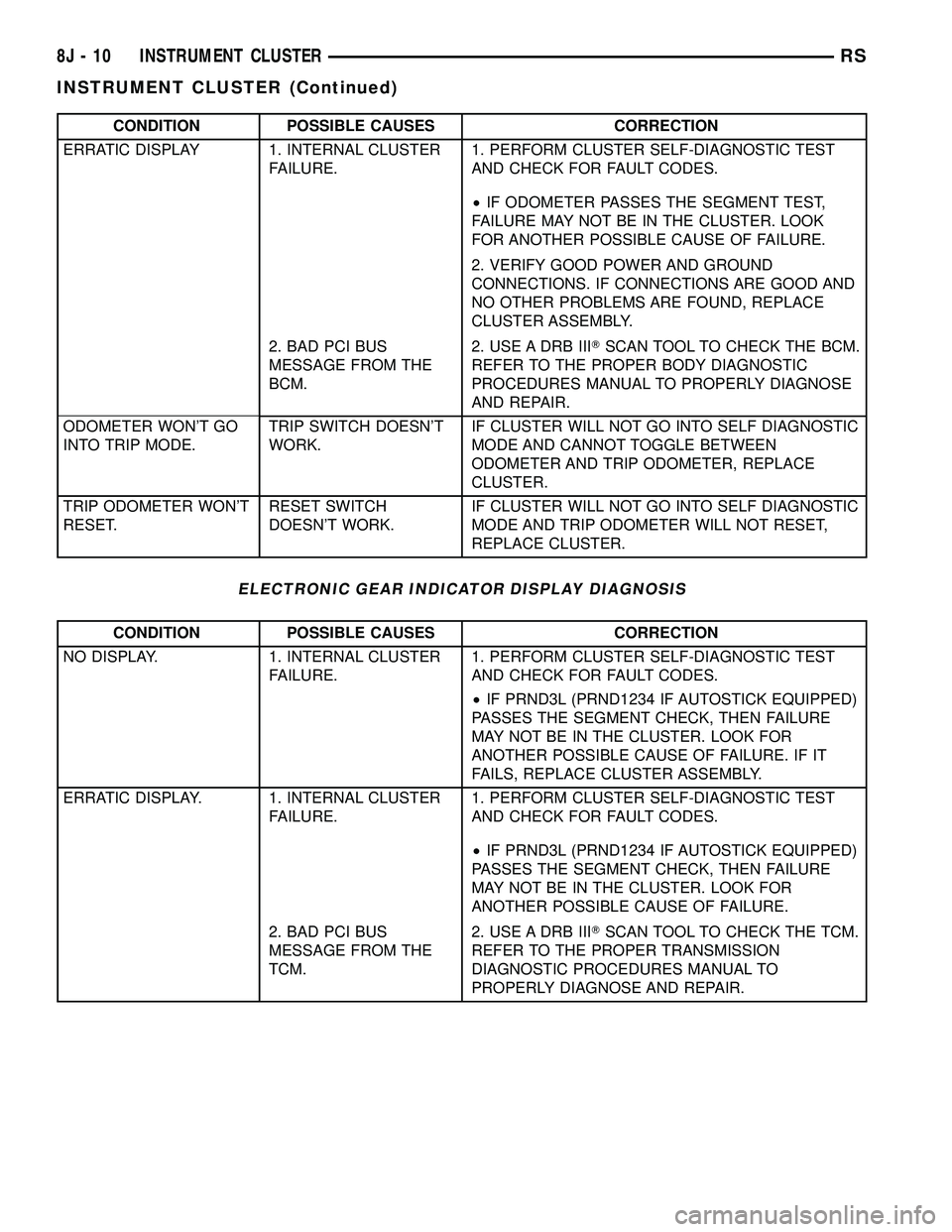
CONDITION POSSIBLE CAUSES CORRECTION
ERRATIC DISPLAY 1. INTERNAL CLUSTER
FAILURE.1. PERFORM CLUSTER SELF-DIAGNOSTIC TEST
AND CHECK FOR FAULT CODES.
²IF ODOMETER PASSES THE SEGMENT TEST,
FAILURE MAY NOT BE IN THE CLUSTER. LOOK
FOR ANOTHER POSSIBLE CAUSE OF FAILURE.
2. VERIFY GOOD POWER AND GROUND
CONNECTIONS. IF CONNECTIONS ARE GOOD AND
NO OTHER PROBLEMS ARE FOUND, REPLACE
CLUSTER ASSEMBLY.
2. BAD PCI BUS
MESSAGE FROM THE
BCM.2. USE A DRB IIITSCAN TOOL TO CHECK THE BCM.
REFER TO THE PROPER BODY DIAGNOSTIC
PROCEDURES MANUAL TO PROPERLY DIAGNOSE
AND REPAIR.
ODOMETER WON'T GO
INTO TRIP MODE.TRIP SWITCH DOESN'T
WORK.IF CLUSTER WILL NOT GO INTO SELF DIAGNOSTIC
MODE AND CANNOT TOGGLE BETWEEN
ODOMETER AND TRIP ODOMETER, REPLACE
CLUSTER.
TRIP ODOMETER WON'T
RESET.RESET SWITCH
DOESN'T WORK.IF CLUSTER WILL NOT GO INTO SELF DIAGNOSTIC
MODE AND TRIP ODOMETER WILL NOT RESET,
REPLACE CLUSTER.
ELECTRONIC GEAR INDICATOR DISPLAY DIAGNOSIS
CONDITION POSSIBLE CAUSES CORRECTION
NO DISPLAY. 1. INTERNAL CLUSTER
FAILURE.1. PERFORM CLUSTER SELF-DIAGNOSTIC TEST
AND CHECK FOR FAULT CODES.
²IF PRND3L (PRND1234 IF AUTOSTICK EQUIPPED)
PASSES THE SEGMENT CHECK, THEN FAILURE
MAY NOT BE IN THE CLUSTER. LOOK FOR
ANOTHER POSSIBLE CAUSE OF FAILURE. IF IT
FAILS, REPLACE CLUSTER ASSEMBLY.
ERRATIC DISPLAY. 1. INTERNAL CLUSTER
FAILURE.1. PERFORM CLUSTER SELF-DIAGNOSTIC TEST
AND CHECK FOR FAULT CODES.
²IF PRND3L (PRND1234 IF AUTOSTICK EQUIPPED)
PASSES THE SEGMENT CHECK, THEN FAILURE
MAY NOT BE IN THE CLUSTER. LOOK FOR
ANOTHER POSSIBLE CAUSE OF FAILURE.
2. BAD PCI BUS
MESSAGE FROM THE
TCM.2. USE A DRB IIITSCAN TOOL TO CHECK THE TCM.
REFER TO THE PROPER TRANSMISSION
DIAGNOSTIC PROCEDURES MANUAL TO
PROPERLY DIAGNOSE AND REPAIR.
8J - 10 INSTRUMENT CLUSTERRS
INSTRUMENT CLUSTER (Continued)
Page 384 of 2339
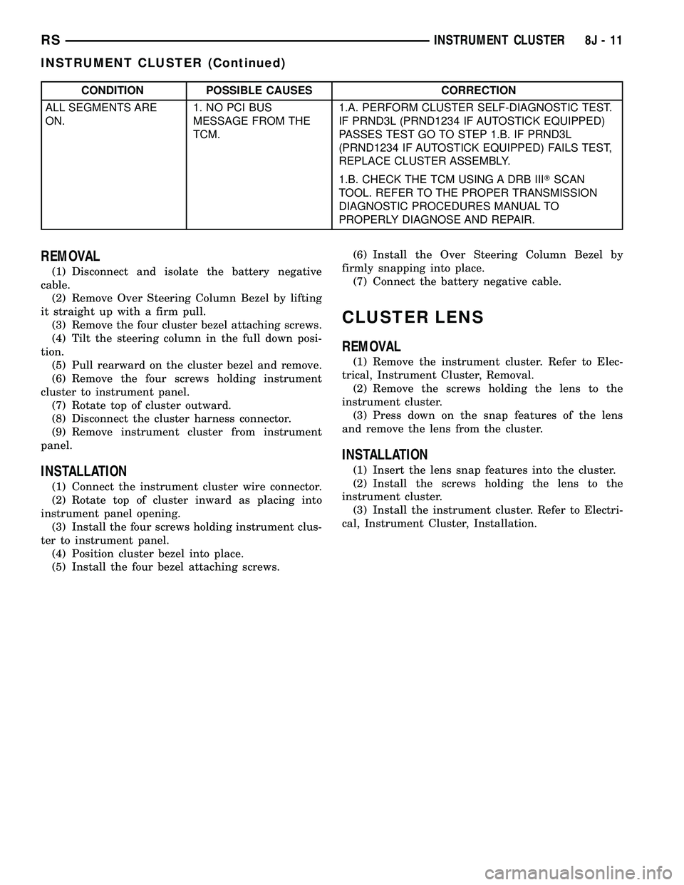
CONDITION POSSIBLE CAUSES CORRECTION
ALL SEGMENTS ARE
ON.1. NO PCI BUS
MESSAGE FROM THE
TCM.1.A. PERFORM CLUSTER SELF-DIAGNOSTIC TEST.
IF PRND3L (PRND1234 IF AUTOSTICK EQUIPPED)
PASSES TEST GO TO STEP 1.B. IF PRND3L
(PRND1234 IF AUTOSTICK EQUIPPED) FAILS TEST,
REPLACE CLUSTER ASSEMBLY.
1.B. CHECK THE TCM USING A DRB IIITSCAN
TOOL. REFER TO THE PROPER TRANSMISSION
DIAGNOSTIC PROCEDURES MANUAL TO
PROPERLY DIAGNOSE AND REPAIR.
REMOVAL
(1) Disconnect and isolate the battery negative
cable.
(2) Remove Over Steering Column Bezel by lifting
it straight up with a firm pull.
(3) Remove the four cluster bezel attaching screws.
(4) Tilt the steering column in the full down posi-
tion.
(5) Pull rearward on the cluster bezel and remove.
(6) Remove the four screws holding instrument
cluster to instrument panel.
(7) Rotate top of cluster outward.
(8) Disconnect the cluster harness connector.
(9) Remove instrument cluster from instrument
panel.
INSTALLATION
(1) Connect the instrument cluster wire connector.
(2) Rotate top of cluster inward as placing into
instrument panel opening.
(3) Install the four screws holding instrument clus-
ter to instrument panel.
(4) Position cluster bezel into place.
(5) Install the four bezel attaching screws.(6) Install the Over Steering Column Bezel by
firmly snapping into place.
(7) Connect the battery negative cable.
CLUSTER LENS
REMOVAL
(1) Remove the instrument cluster. Refer to Elec-
trical, Instrument Cluster, Removal.
(2) Remove the screws holding the lens to the
instrument cluster.
(3) Press down on the snap features of the lens
and remove the lens from the cluster.
INSTALLATION
(1) Insert the lens snap features into the cluster.
(2) Install the screws holding the lens to the
instrument cluster.
(3) Install the instrument cluster. Refer to Electri-
cal, Instrument Cluster, Installation.
RSINSTRUMENT CLUSTER8J-11
INSTRUMENT CLUSTER (Continued)
Page 455 of 2339
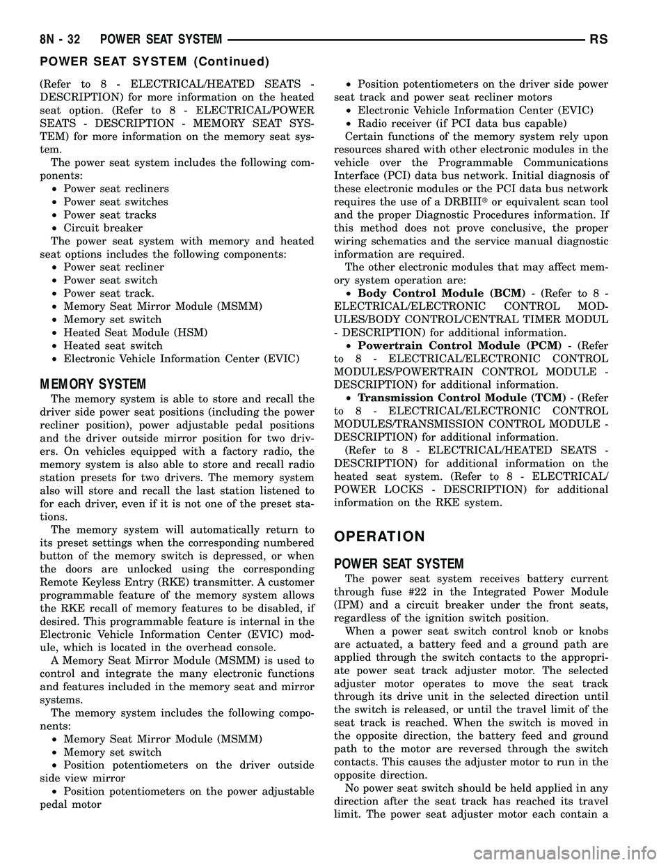
(Refer to 8 - ELECTRICAL/HEATED SEATS -
DESCRIPTION) for more information on the heated
seat option. (Refer to 8 - ELECTRICAL/POWER
SEATS - DESCRIPTION - MEMORY SEAT SYS-
TEM) for more information on the memory seat sys-
tem.
The power seat system includes the following com-
ponents:
²Power seat recliners
²Power seat switches
²Power seat tracks
²Circuit breaker
The power seat system with memory and heated
seat options includes the following components:
²Power seat recliner
²Power seat switch
²Power seat track.
²Memory Seat Mirror Module (MSMM)
²Memory set switch
²Heated Seat Module (HSM)
²Heated seat switch
²Electronic Vehicle Information Center (EVIC)
MEMORY SYSTEM
The memory system is able to store and recall the
driver side power seat positions (including the power
recliner position), power adjustable pedal positions
and the driver outside mirror position for two driv-
ers. On vehicles equipped with a factory radio, the
memory system is also able to store and recall radio
station presets for two drivers. The memory system
also will store and recall the last station listened to
for each driver, even if it is not one of the preset sta-
tions.
The memory system will automatically return to
its preset settings when the corresponding numbered
button of the memory switch is depressed, or when
the doors are unlocked using the corresponding
Remote Keyless Entry (RKE) transmitter. A customer
programmable feature of the memory system allows
the RKE recall of memory features to be disabled, if
desired. This programmable feature is internal in the
Electronic Vehicle Information Center (EVIC) mod-
ule, which is located in the overhead console.
A Memory Seat Mirror Module (MSMM) is used to
control and integrate the many electronic functions
and features included in the memory seat and mirror
systems.
The memory system includes the following compo-
nents:
²Memory Seat Mirror Module (MSMM)
²Memory set switch
²Position potentiometers on the driver outside
side view mirror
²Position potentiometers on the power adjustable
pedal motor²Position potentiometers on the driver side power
seat track and power seat recliner motors
²Electronic Vehicle Information Center (EVIC)
²Radio receiver (if PCI data bus capable)
Certain functions of the memory system rely upon
resources shared with other electronic modules in the
vehicle over the Programmable Communications
Interface (PCI) data bus network. Initial diagnosis of
these electronic modules or the PCI data bus network
requires the use of a DRBIIItor equivalent scan tool
and the proper Diagnostic Procedures information. If
this method does not prove conclusive, the proper
wiring schematics and the service manual diagnostic
information are required.
The other electronic modules that may affect mem-
ory system operation are:
²Body Control Module (BCM)- (Refer to 8 -
ELECTRICAL/ELECTRONIC CONTROL MOD-
ULES/BODY CONTROL/CENTRAL TIMER MODUL
- DESCRIPTION) for additional information.
²Powertrain Control Module (PCM)- (Refer
to 8 - ELECTRICAL/ELECTRONIC CONTROL
MODULES/POWERTRAIN CONTROL MODULE -
DESCRIPTION) for additional information.
²Transmission Control Module (TCM)- (Refer
to 8 - ELECTRICAL/ELECTRONIC CONTROL
MODULES/TRANSMISSION CONTROL MODULE -
DESCRIPTION) for additional information.
(Refer to 8 - ELECTRICAL/HEATED SEATS -
DESCRIPTION) for additional information on the
heated seat system. (Refer to 8 - ELECTRICAL/
POWER LOCKS - DESCRIPTION) for additional
information on the RKE system.
OPERATION
POWER SEAT SYSTEM
The power seat system receives battery current
through fuse #22 in the Integrated Power Module
(IPM) and a circuit breaker under the front seats,
regardless of the ignition switch position.
When a power seat switch control knob or knobs
are actuated, a battery feed and a ground path are
applied through the switch contacts to the appropri-
ate power seat track adjuster motor. The selected
adjuster motor operates to move the seat track
through its drive unit in the selected direction until
the switch is released, or until the travel limit of the
seat track is reached. When the switch is moved in
the opposite direction, the battery feed and ground
path to the motor are reversed through the switch
contacts. This causes the adjuster motor to run in the
opposite direction.
No power seat switch should be held applied in any
direction after the seat track has reached its travel
limit. The power seat adjuster motor each contain a
8N - 32 POWER SEAT SYSTEMRS
POWER SEAT SYSTEM (Continued)
Page 533 of 2339
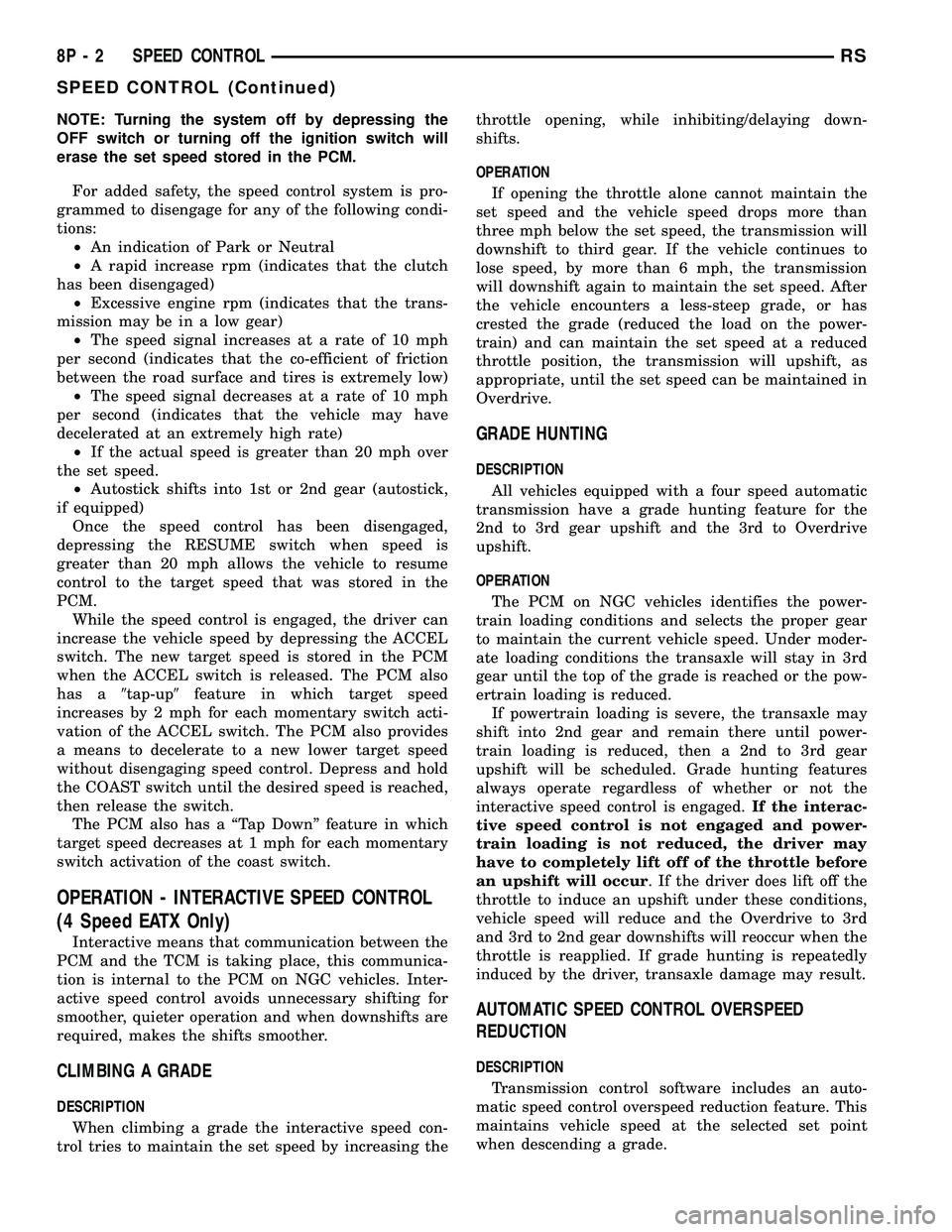
NOTE: Turning the system off by depressing the
OFF switch or turning off the ignition switch will
erase the set speed stored in the PCM.
For added safety, the speed control system is pro-
grammed to disengage for any of the following condi-
tions:
²An indication of Park or Neutral
²A rapid increase rpm (indicates that the clutch
has been disengaged)
²Excessive engine rpm (indicates that the trans-
mission may be in a low gear)
²The speed signal increases at a rate of 10 mph
per second (indicates that the co-efficient of friction
between the road surface and tires is extremely low)
²The speed signal decreases at a rate of 10 mph
per second (indicates that the vehicle may have
decelerated at an extremely high rate)
²If the actual speed is greater than 20 mph over
the set speed.
²Autostick shifts into 1st or 2nd gear (autostick,
if equipped)
Once the speed control has been disengaged,
depressing the RESUME switch when speed is
greater than 20 mph allows the vehicle to resume
control to the target speed that was stored in the
PCM.
While the speed control is engaged, the driver can
increase the vehicle speed by depressing the ACCEL
switch. The new target speed is stored in the PCM
when the ACCEL switch is released. The PCM also
has a9tap-up9feature in which target speed
increases by 2 mph for each momentary switch acti-
vation of the ACCEL switch. The PCM also provides
a means to decelerate to a new lower target speed
without disengaging speed control. Depress and hold
the COAST switch until the desired speed is reached,
then release the switch.
The PCM also has a ªTap Downº feature in which
target speed decreases at 1 mph for each momentary
switch activation of the coast switch.
OPERATION - INTERACTIVE SPEED CONTROL
(4 Speed EATX Only)
Interactive means that communication between the
PCM and the TCM is taking place, this communica-
tion is internal to the PCM on NGC vehicles. Inter-
active speed control avoids unnecessary shifting for
smoother, quieter operation and when downshifts are
required, makes the shifts smoother.
CLIMBING A GRADE
DESCRIPTION
When climbing a grade the interactive speed con-
trol tries to maintain the set speed by increasing thethrottle opening, while inhibiting/delaying down-
shifts.
OPERATION
If opening the throttle alone cannot maintain the
set speed and the vehicle speed drops more than
three mph below the set speed, the transmission will
downshift to third gear. If the vehicle continues to
lose speed, by more than 6 mph, the transmission
will downshift again to maintain the set speed. After
the vehicle encounters a less-steep grade, or has
crested the grade (reduced the load on the power-
train) and can maintain the set speed at a reduced
throttle position, the transmission will upshift, as
appropriate, until the set speed can be maintained in
Overdrive.
GRADE HUNTING
DESCRIPTION
All vehicles equipped with a four speed automatic
transmission have a grade hunting feature for the
2nd to 3rd gear upshift and the 3rd to Overdrive
upshift.
OPERATION
The PCM on NGC vehicles identifies the power-
train loading conditions and selects the proper gear
to maintain the current vehicle speed. Under moder-
ate loading conditions the transaxle will stay in 3rd
gear until the top of the grade is reached or the pow-
ertrain loading is reduced.
If powertrain loading is severe, the transaxle may
shift into 2nd gear and remain there until power-
train loading is reduced, then a 2nd to 3rd gear
upshift will be scheduled. Grade hunting features
always operate regardless of whether or not the
interactive speed control is engaged.If the interac-
tive speed control is not engaged and power-
train loading is not reduced, the driver may
have to completely lift off of the throttle before
an upshift will occur. If the driver does lift off the
throttle to induce an upshift under these conditions,
vehicle speed will reduce and the Overdrive to 3rd
and 3rd to 2nd gear downshifts will reoccur when the
throttle is reapplied. If grade hunting is repeatedly
induced by the driver, transaxle damage may result.
AUTOMATIC SPEED CONTROL OVERSPEED
REDUCTION
DESCRIPTION
Transmission control software includes an auto-
matic speed control overspeed reduction feature. This
maintains vehicle speed at the selected set point
when descending a grade.
8P - 2 SPEED CONTROLRS
SPEED CONTROL (Continued)
Page 1026 of 2339
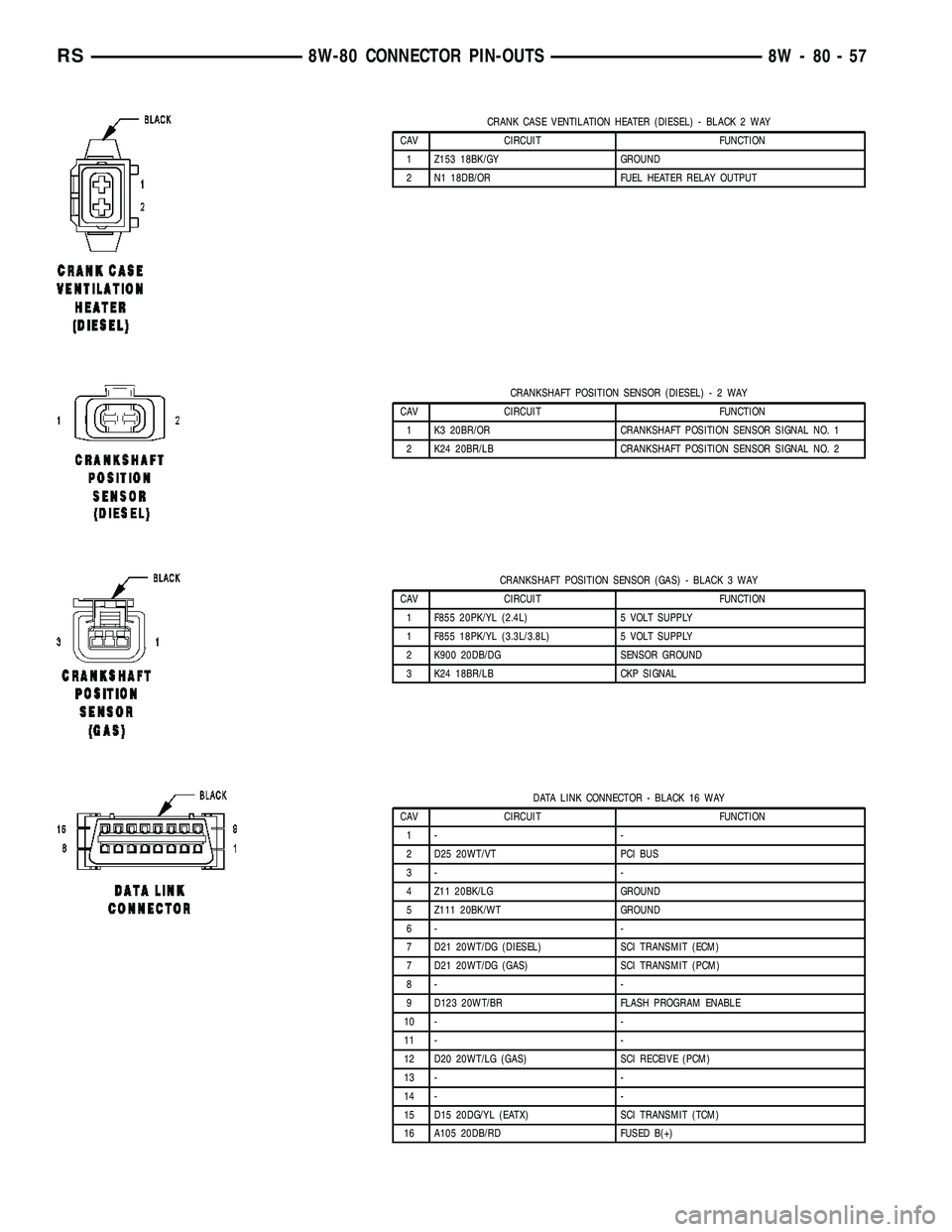
CRANK CASE VENTILATION HEATER (DIESEL) - BLACK 2 WAY
CAV CIRCUIT FUNCTION
1 Z153 18BK/GY GROUND
2 N1 18DB/OR FUEL HEATER RELAY OUTPUT
CRANKSHAFT POSITION SENSOR (DIESEL)-2WAY
CAV CIRCUIT FUNCTION
1 K3 20BR/OR CRANKSHAFT POSITION SENSOR SIGNAL NO. 1
2 K24 20BR/LB CRANKSHAFT POSITION SENSOR SIGNAL NO. 2
CRANKSHAFT POSITION SENSOR (GAS) - BLACK 3 WAY
CAV CIRCUIT FUNCTION
1 F855 20PK/YL (2.4L) 5 VOLT SUPPLY
1 F855 18PK/YL (3.3L/3.8L) 5 VOLT SUPPLY
2 K900 20DB/DG SENSOR GROUND
3 K24 18BR/LB CKP SIGNAL
DATA LINK CONNECTOR - BLACK 16 WAY
CAV CIRCUIT FUNCTION
1- -
2 D25 20WT/VT PCI BUS
3- -
4 Z11 20BK/LG GROUND
5 Z111 20BK/WT GROUND
6- -
7 D21 20WT/DG (DIESEL) SCI TRANSMIT (ECM)
7 D21 20WT/DG (GAS) SCI TRANSMIT (PCM)
8- -
9 D123 20WT/BR FLASH PROGRAM ENABLE
10 - -
11 - -
12 D20 20WT/LG (GAS) SCI RECEIVE (PCM)
13 - -
14 - -
15 D15 20DG/YL (EATX) SCI TRANSMIT (TCM)
16 A105 20DB/RD FUSED B(+)
RS8W-80 CONNECTOR PIN-OUTS8W-80-57
Page 1085 of 2339
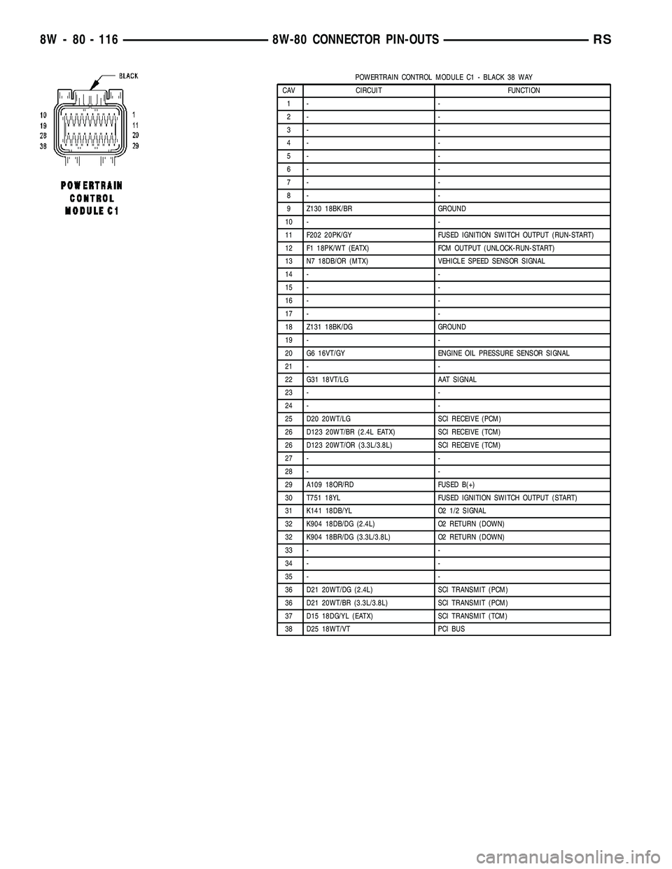
POWERTRAIN CONTROL MODULE C1 - BLACK 38 WAY
CAV CIRCUIT FUNCTION
1- -
2- -
3- -
4- -
5- -
6- -
7- -
8- -
9 Z130 18BK/BR GROUND
10 - -
11 F202 20PK/GY FUSED IGNITION SWITCH OUTPUT (RUN-START)
12 F1 18PK/WT (EATX) FCM OUTPUT (UNLOCK-RUN-START)
13 N7 18DB/OR (MTX) VEHICLE SPEED SENSOR SIGNAL
14 - -
15 - -
16 - -
17 - -
18 Z131 18BK/DG GROUND
19 - -
20 G6 16VT/GY ENGINE OIL PRESSURE SENSOR SIGNAL
21 - -
22 G31 18VT/LG AAT SIGNAL
23 - -
24 - -
25 D20 20WT/LG SCI RECEIVE (PCM)
26 D123 20WT/BR (2.4L EATX) SCI RECEIVE (TCM)
26 D123 20WT/OR (3.3L/3.8L) SCI RECEIVE (TCM)
27 - -
28 - -
29 A109 18OR/RD FUSED B(+)
30 T751 18YL FUSED IGNITION SWITCH OUTPUT (START)
31 K141 18DB/YL O2 1/2 SIGNAL
32 K904 18DB/DG (2.4L) O2 RETURN (DOWN)
32 K904 18BR/DG (3.3L/3.8L) O2 RETURN (DOWN)
33 - -
34 - -
35 - -
36 D21 20WT/DG (2.4L) SCI TRANSMIT (PCM)
36 D21 20WT/BR (3.3L/3.8L) SCI TRANSMIT (PCM)
37 D15 18DG/YL (EATX) SCI TRANSMIT (TCM)
38 D25 18WT/VT PCI BUS
8W - 80 - 116 8W-80 CONNECTOR PIN-OUTSRS