spare wheel CITROEN BERLINGO VAN 2021 User Guide
[x] Cancel search | Manufacturer: CITROEN, Model Year: 2021, Model line: BERLINGO VAN, Model: CITROEN BERLINGO VAN 2021Pages: 324, PDF Size: 9.41 MB
Page 173 of 324
171
Driving
6Interruption by the driver:
– taking over control of the steering.
–
activating the direction indicator lamps on the
opposite side to that of the manoeuvre.
–
unfastening the driver's seat belt.
–
switching off the ignition.
Interruption by the system:
–
vehicle exceeding the speed limit of
5
mph (7 km/h) during parking space entry
manoeuvres, or 3
mph (5 km/h) during parking
space exit manoeuvres.
–
activation of anti-slip regulation on a slippery
road.
–
opening of a door or the boot.
–
engine stall.
–
system malfunction.
–
after 10 manoeuvres to enter or exit a parallel
parking space and after 7 manoeuvres to enter a
parking bay
.
Interrupting the manoeuvre automatically
deactivates the function.
The manoeuvre symbol is displayed in red,
accompanied by the " Manoeuvre cancelled"
message on the touch screen.
A message prompts the driver to take back
control of the vehicle.
The function is deactivated after a few seconds; this indicator lamp goes off and
the function returns to the initial display.
End of the parking space entry or exit
manoeuvre
The vehicle stops as soon as the manoeuvre is
completed.
The manoeuvre symbol is displayed in red,
accompanied by the message " Manoeuvre
completed" on the touch screen.
When the function is deactivated, this
indicator lamp goes off, accompanied by
an audible signal.
When entering a parking space, the driver may
be required to complete the manoeuvre.
Operating limits
– The system may suggest an inappropriate
parking space (parking prohibited, work in
progress with damaged road surface, location
alongside a ditch, etc.).
–
The system may indicate that a space has
been found but will not offer it because of a fixed
obstacle on the opposite side of the manoeuvre,
which would not allow the vehicle to follow a
trajectory required for parking.
–
The system may indicate that a space has
been found but the manoeuvre will not be
triggered, because the width of the lane is
insufficient.
–
The system is not designed for performing the
parking manoeuvre on a sharp bend.
–
The system does not detect spaces that
are much larger than the vehicle itself or that
are delimited by obstacles that are too low
(pavements, studs, etc.) or too thin (trees, posts,
wire fences, etc.).
–
If the boot is heavily loaded, the tilt of the
vehicle towards the rear may interfere with the
distance measurements.
Do not use the function under the
following exterior conditions:
–
Alongside a soft shoulder (e.g. ditch) or
quay or on the edge of a drop.
–
When the road surface is slippery (e.g. ice).
If any of the following malfunctions
occurs, do not use the system:
–
If a tyre is under-inflated.
–
If one of the bumpers is damaged.
–
If one of the cameras is faulty
.
If the vehicle has undergone any of the
following modifications, do not use the
function:
–
When carrying an object extending beyond
the dimensions of the vehicle (ladder on the
roof bars, bicycle carrier on the tailgate, etc.).
–
With a non-approved towball in place.
–
With snow chains fitted.
–
When driving on a small-diameter or
"space-saver" type spare wheel.
–
When the wheels fitted are a different size
from the original ones.
–
After modifying one or both bumpers
(added protection).
Page 190 of 324
188
Practical information
Load reduction mode
This system manages the use of certain
functions according to the level of charge
remaining in the battery.
When the vehicle is being driven, the load
reduction function temporarily deactivates certain
functions, such as the air conditioning and the
heated rear screen.
The deactivated functions are reactivated
automatically as soon as conditions permit.
Snow chains
In wintry conditions, snow chains improve
traction as well as the behaviour of the vehicle
when braking.
Snow chains must be fitted only to the
front wheels. They must never be fitted to
"space-saver" type spare wheels.
Observe the legislation in force in your
country relating to the use of snow
chains and maximum authorised speeds.
Use only the chains designed to be fitted to the
type of wheel fitted to your vehicle:
Original tyre size Link size: (mm) 195/65 R15 9
205/60 R16
205/55 R17
215/65 R16
215/60 R17 Cannot be fitted with
chains
You can also use snow socks.
For more information, contact a CITROËN dealer
or a qualified workshop.
Installation tips
► To fit the snow chains during a journey, stop
the vehicle on a flat surface at the side of the
road.
►
Apply the parking brake and position any
wheel chocks under the wheels to prevent
movement of the vehicle.
►
Fit the snow chains following the instructions
provided by the manufacturer
.
►
Move off gently and drive for a few moments,
without exceeding 31
mph (50 km/h).
►
Stop the vehicle and check that the snow
chains are correctly tightened.
It is strongly recommended that you
practise fitting the snow chains on a level
and dry surface before setting off.
Avoid driving with snow chains on roads that have been cleared of snow to avoid
damaging the vehicle's tyres and the road
surface. If the vehicle is fitted with alloy
wheels, check that no part of the chain or its
fixings is in contact with the wheel rim.
Very cold climate screen
(Depending on country of sale)
This removable device prevents the
accumulation of snow around the radiator
cooling fan.
Page 199 of 324
197
Practical information
7brake must be adjusted, even between two
services.
This system must be checked by a CITROËN
dealer or a qualified workshop.
Electric parking brake
This system does not require any routine servicing. However, in the event of a
problem, do not hesitate to have the system
checked by a CITROËN dealer or a qualified
workshop.
For more information on the Electric
parking brake, refer to the
corresponding section.
Wheels and tyres
The inflation pressure of all tyres, including the spare wheel, must be
checked on "cold” tyres.
The pressures indicated on the tyre pressure
label are valid for "cold" tyres. If you have driven
for more than 10 minutes or more than 6 miles
(10 kilometres) at over 31 mph (50
km/h), add
0.3 bar (30 kPa) to the values indicated on the
label.
Under-inflation increases energy
consumption. Non-compliant tyre
pressures cause tyres to wear prematurely
and have an adverse effect on the vehicle's
road holding - risk of accident! Driving with worn or damaged tyres reduces the
braking and road holding performance of the
vehicle. Regularly check the condition of the
tyres (tread and sidewalls) and rims as well as
the presence of the valve caps.
When the wear indicators no longer appear set
back from the tread, the depth of the grooves is
less than 1.6 mm; replace the tyres as soon as
possible.
Using different size wheels and tyres from those
specified can affect the lifetime of tyres, wheel
rotation, ground clearance, the speedometer
reading and have an adverse effect on road
holding.
Fitting different tyres on the front and rear axles
can cause the ESC to mistime.
Always mark the direction of rotation on the tyres
that will be stored when fitting winter or summer
tyres. Store them in a cool, dry place and away
from direct exposure to the sun's rays.
Winter or 4-seasons tyres can be
identified by this symbol on their
sidewalls.
AdBlue® (BlueHDi)
To respect the environment and ensure compliance with the Euro 6 standard, without
adversely affecting the performance or fuel
consumption of its Diesel engines, CITROËN
has taken the decision to equip its vehicles with
a system that combines SCR (Selective Catalytic
Reduction) with a Diesel Particle Filter (DPF) for
the treatment of exhaust gases.
SCR system
Using a liquid called AdBlue® that contains
urea, a catalytic converter turns up to 85% of
the nitrogen oxides (NOx) into nitrogen and
water, which are harmless to health and the
environment.
The AdBlue® is contained in a special
tank holding about 17 litres.
Its capacity allows a driving range of
approximately 3,000
miles (5,000 km) (which
may vary considerably depending on your
driving style and the vehicle). An alert system
is automatically triggered when the remaining
range reaches 1,500 miles (2,400
km), i.e. once
the reserve level has been reached.
Several alerts are triggered successively during
the remaining 1,500 miles (2,400
km) until the
tank is empty and the vehicle is immobilised.
For more information on the Warning
and indicator lamps and the associated
alerts, or the Indicators, please refer to the
corresponding sections.
Once the AdBlue® tank is empty, a device
required by law prevents the engine from
being restarted.
If the SCR system is faulty, the level of
emissions from the vehicle will no longer meet
Page 204 of 324
202
In the event of a breakdown
Running out of fuel
(Diesel)
With Diesel engines, the fuel system must be
primed if you run out of fuel.
Before starting to prime the system, it is
essential to put at least 5 litres of Diesel into the
fuel tank.
For more information on Refuelling and
on Misfuel prevention (Diesel), refer to
the corresponding section.
For non-BlueHDi versions, the fuel system
components are located in the engine
compartment; this may be under a removable
cover.
For more information on the Engine
compartment, in particular the location
of these components under the bonnet, refer
to the corresponding section.
With 1.6 BlueHDi (Euro 6.1)
► Switch on the ignition (without starting the
engine).
►
W
ait around 6 seconds and switch off the
ignition.
►
Repeat the operation 10
times.
►
Operate the starter motor to start the engine.
If the engine does not start at the first attempt,
do not keep trying, but restart the procedure.
With 1.5 BlueHDi (Euro 6.2/6.3)
► Switch on the ignition (without starting the
engine).
►
W
ait around 1 minute and switch off the
ignition.
►
Operate the starter motor to start the engine.
If the engine does not start at the first attempt,
do not keep trying, but restart the procedure.
Non-BlueHDi engines
► Open the bonnet and then, if necessary ,
unclip the cover to access the priming pump.
► Operate the priming pump repeatedly
until resistance is felt (resistance may be
felt at the first press).
►
Operate the starter motor to start the engine
(if the engine does not start at the first attempt,
wait around 15 seconds before trying again).
►
If the engine does not start after a few
attempts, operate the priming pump again, then
the starter motor
.
►
Put the cover back in place and clip it in, then
close the bonnet.
Tool kit
► For easier access, move the seat(s) forward.
Accessing the tools
Vehicle with electric motor
With temporary puncture repair kit
The tools are located in the passenger footwell. With spare wheel
The tools are located under the right-hand front
seat.
To access the tools:
–
With non-adjustable front seat, lift the seat
cushion by placing your hand between the
cushion and the backrest.
–
With adjustable front seat, move the seat
forward as far as possible.
The jack is located in the passenger footwell.
Vehicle with Petrol or Diesel engine
With temporary puncture repair kit
The kit is located under the right-hand front seat.
With spare wheel
The jack is located under the right-hand front
seat.
The tools are located under the left-hand front
seat.
List of tools
1. Chock to immobilise the vehicle
2. Removable towing eye
Page 205 of 324
203
In the event of a breakdown
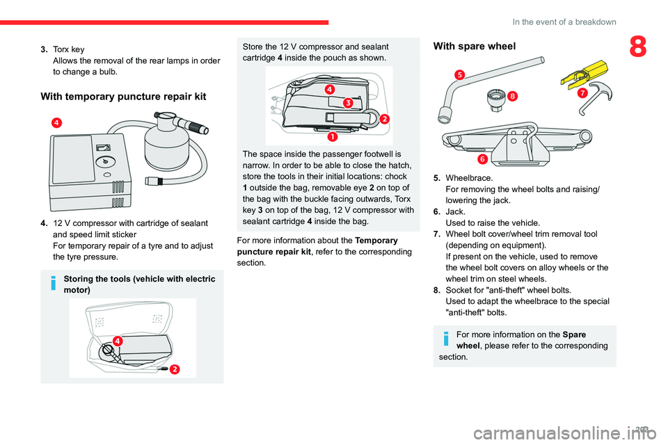
83.Torx key
Allows the removal of the rear lamps in order
to change a bulb.
With temporary puncture repair kit
4.12 V compressor with cartridge of sealant
and speed limit sticker
For temporary repair of a tyre and to adjust
the tyre pressure.
Storing the tools (vehicle with electric
motor)
Store the 12 V compressor and sealant
cartridge 4 inside the pouch as shown.
The space inside the passenger footwell is
narrow. In order to be able to close the hatch,
store the tools in their initial locations: chock
1 outside the bag, removable eye
2
on top of
the bag with the buckle facing outwards, Torx
key 3 on top of the bag, 12
V compressor with
sealant cartridge 4 inside the bag.
For more information about the Temporary
puncture repair kit, refer to the corresponding
section.
With spare wheel
5. Wheelbrace.
For removing the wheel bolts and raising/
lowering the jack.
6. Jack.
Used to raise the vehicle.
7. Wheel bolt cover/wheel trim removal tool
(depending on equipment).
If present on the vehicle, used to remove
the wheel bolt covers on alloy wheels or the
wheel trim on steel wheels.
8. Socket for "anti-theft" wheel bolts.
Used to adapt the wheelbrace to the special
"anti-theft" bolts.
For more information on the Spare
wheel, please refer to the corresponding
section.
Page 208 of 324
206
In the event of a breakdown
Should the pressure of one or more tyres
be adjusted, it is necessary to reinitialise
the under-inflation detection system.
For more information on Tyre under-inflation
detection, refer to the corresponding section.
Spare wheel
Scan the QR Code on page 3 to view
explanatory videos.
For more information on the Tool kit,
refer to the corresponding section.
►
Park the vehicle without obstructing traffic
and apply the parking brake.
►
Follow the safety instructions (hazard
warning lamps, warning triangle, wearing high
visibility jacket, etc.) according to the legislation
in force in the country in which you are driving.
►
Switch the ignition off.
Accessing the spare wheel
► Access to the spare wheel is from the rear .
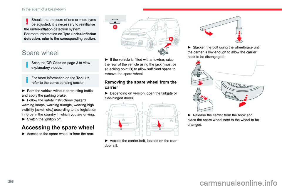
► If the vehicle is fitted with a towbar, raise
the rear of the vehicle using the jack (must be
at jacking point B) to allow sufficient space to
remove the spare wheel.
Removing the spare wheel from the
carrier
► Depending on version, open the tailgate or
side-hinged doors.
► Access the carrier bolt, located on the rear
door sill.
► Slacken the bolt using the wheelbrace until
the carrier is low enough to allow the carrier
hook to be disengaged.
► Release the carrier from the hook and
place the spare wheel next to the wheel to be
changed.
Page 209 of 324
207
In the event of a breakdown
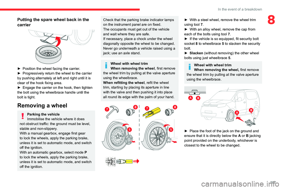
8Putting the spare wheel back in the
carrier
► Position the wheel facing the carrier.
► Progressively return the wheel to the carrier
by pushing alternately at left and right until it is
clear of the hook fixing area.
►
Engage the carrier on the hook, then tighten
the bolt using the wheelbrace handle until the
bolt is tight.
Removing a wheel
Parking the vehicle
Immobilise the vehicle where it does
not obstruct traffic: the ground must be level,
stable and non-slippery.
With a manual gearbox, engage first gear
to lock the wheels, apply the parking brake,
unless it is set to automatic mode, and switch
off the ignition.
With an automatic gearbox, select mode
P
to lock the wheels, apply the parking brake,
unless it is set to automatic mode, and switch
off the ignition.
Check that the parking brake indicator lamps
on the instrument panel are on fixed.
The occupants must get out of the vehicle
and wait where they are safe.
If necessary, place a chock under the wheel
diagonally opposite the wheel to be changed.
Never go underneath a vehicle raised using a
jack; use an axle stand.
Wheel with wheel trim
When removing the wheel , first remove
the wheel trim by pulling at the valve aperture
using the wheelbrace.
When refitting the wheel , refit the wheel
trim, starting by placing its aperture in line
with the valve and then pushing it into place
all round its edge with the palm of your hand.
► With a steel wheel, remove the wheel trim
using tool 7
.
►
With an alloy wheel, remove the cap from
each of the bolts using tool 7
.
►
If the vehicle is so equipped, fit security bolt
socket
8 to wheelbrace 5 to slacken the security
bolt.
►
Slacken
(without removing) the other wheel
bolts using just wheelbrace 5.
Wheel with wheel trim
When removing the wheel, first remove
the wheel trim by pulling at the valve aperture
using the wheelbrace.
► Place the foot of the jack on the ground and
ensure that it is directly below the A
or B jacking
point provided on the underbody, whichever is
closest to the wheel to be changed.
Page 210 of 324
208
In the event of a breakdown
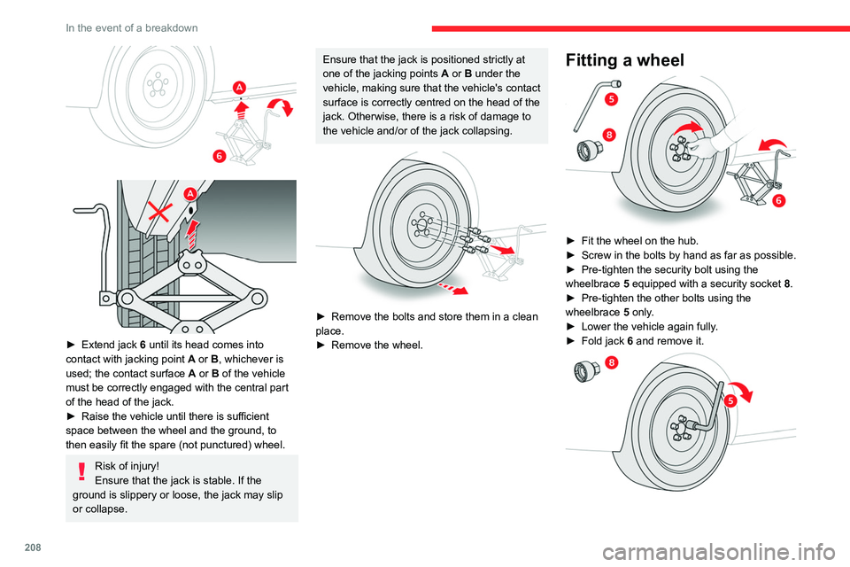
► Extend jack 6 until its head comes into
contact with jacking point A or B, whichever is
used; the contact surface A or B of the vehicle
must be correctly engaged with the central part
of the head of the jack.
►
Raise the vehicle until there is sufficient
space between the wheel and the ground, to
then easily fit the spare (not punctured) wheel.
Risk of injury!
Ensure that the jack is stable. If the
ground is slippery or loose, the jack may slip
or collapse.
Ensure that the jack is positioned strictly at
one of the jacking points A or B under the
vehicle, making sure that the vehicle's contact
surface is correctly centred on the head of the
jack. Otherwise, there is a risk of damage to
the vehicle and/or of the jack collapsing.
► Remove the bolts and store them in a clean
place.
►
Remove the wheel.
Fitting a wheel
► Fit the wheel on the hub.
► Screw in the bolts by hand as far as possible.
►
Pre-tighten the security bolt using the
wheelbrace
5
equipped with a security socket
8
.
►
Pre-tighten the other bolts using the
wheelbrace
5
only.
►
Lower the vehicle again fully
.
►
Fold jack
6 and remove it.
Page 211 of 324
209
In the event of a breakdown
8► If your vehicle is so equipped, tighten the
security bolt using the wheelbrace 5 equipped
with a security socket
8.
►
T
ighten the other bolts using the
wheelbrace
5
only.
►
Store the tools.
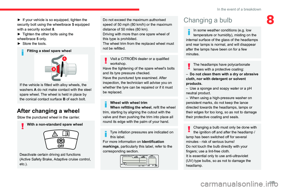
Fitting a steel spare wheel
If the vehicle is fitted with alloy wheels, the
washers A do not make contact with the steel
spare wheel. The wheel is held in place by
the conical contact surface B of each bolt.
After changing a wheel
Stow the punctured wheel in the carrier.
With a non-standard spare wheel
Deactivate certain driving aid functions
(Active Safety Brake, Adaptive cruise control,
etc.).
Do not exceed the maximum authorised
speed of 50 mph (80
km/h) or the maximum
distance of 50 miles (80 km).
Driving with more than one spare wheel of
this type is prohibited.
The wheel trim from the replaced wheel must
not be refitted.
Visit a CITROËN dealer or a qualified
workshop.
Have the tightening of the spare wheel's bolts
and its tyre pressure checked.
Have the punctured tyre examined. After
inspection, the technician will advise you on
whether the tyre can be repaired or if it must
be replaced.
Wheel with wheel trim
When refitting the wheel, refit the wheel
trim, starting by aligning the cutout with the
valve and then pushing the trim into place all
round its edge with the palm of your hand.
Tyre inflation pressures are indicated on this label.
For more information on Identification
markings, particularly this label, refer to the
corresponding section.
Changing a bulb
In some weather conditions (e.g. low
temperature or humidity), misting on the
internal surface of the glass of the headlamps
and rear lamps is normal, and will disappear
after the lamps have been on for a few
minutes.
The headlamps have polycarbonate lenses with a protective coating:
–
Do not clean them with a dry or abrasive
cloth, nor with detergent or solvent
products.
–
Use a sponge and soapy water or a pH
neutral product.
–
When using a high-pressure washer on
persistent marks, do not keep the lance
directed towards the headlamps, lamps or
their edges for too long, so as not to damage
their protective coating and seals.
Changing a bulb must only be done with
the ignition off and after the headlamp /
lamp has been switched off for several
minutes - risk of serious burns!
Do not touch the bulb directly with your
fingers; use a lint-free cloth.
It is essential only to use anti-ultraviolet
(UV) type bulbs, so as not to damage the
headlamp.
Page 238 of 324
236
Technical data
Identification markings
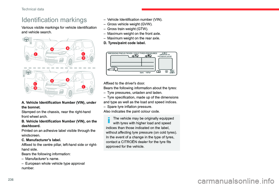
Various visible markings for vehicle identification
and vehicle search.
A. Vehicle Identification Number (VIN), under
the bonnet.
Stamped on the chassis, near the right-hand
front wheel arch.
B. Vehicle Identification Number (VIN), on the
dashboard.
Printed on an adhesive label visible through the
windscreen.
C. Manufacturer's label.
Affixed to the centre pillar, left-hand side or right-
hand side.
Bears the following information:
–
Manufacturer
’s name.
–
European whole vehicle type approval
number
.
– Vehicle Identification number (VIN).
– Gross vehicle weight (GVW).
–
Gross train weight (GTW).
–
Maximum weight on the front axle.
–
Maximum weight on the rear axle.
D. T
yres/paint code label.
Affixed to the driver's door.
Bears the following information about the tyres:
–
T
yre pressures, unladen and laden.
–
T
yre specification, made up of the dimensions
and type as well as the load and speed indices.
–
Spare tyre inflation pressure.
Also indicates the paint colour code.
The vehicle may be originally equipped with tyres with higher load and speed
indices than those indicated on the label,
without affecting tyre pressure (on cold tyres).
In the event of a change in the type of tyres,
contact a CITROËN dealer for the tyre fits
approved for the vehicle.