sensor Citroen C5 2000 (DC/DE) / 1.G User Guide
[x] Cancel search | Manufacturer: CITROEN, Model Year: 2000, Model line: C5, Model: Citroen C5 2000 (DC/DE) / 1.GPages: 259, PDF Size: 2.29 MB
Page 126 of 259

Downloaded from www.Manualslib.com manuals search engine 123
INJECTION
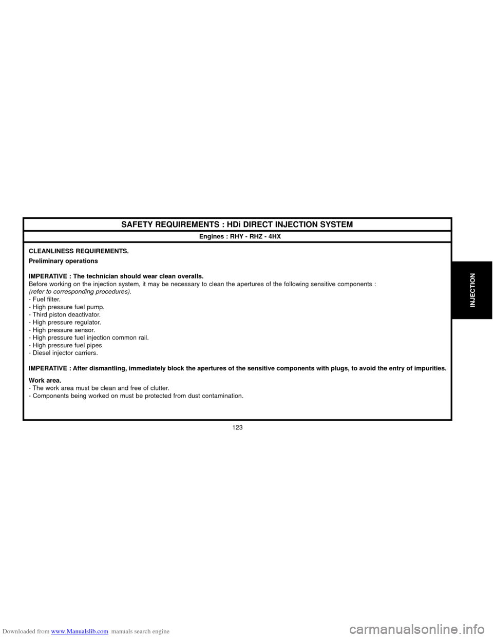
SAFETY REQUIREMENTS : HDi DIRECT INJECTION SYSTEM
Engines : RHY - RHZ - 4HX
CLEANLINESS REQUIREMENTS.
Preliminary operations
IMPERATIVE : The technician should wear clean overalls.
Before working on the injection system, it may be necessary to clean the apertures of the following sensitive components :
(refer to corresponding procedures).
- Fuel filter.
- High pressure fuel pump.
- Third piston deactivator.
- High pressure regulator.
- High pressure sensor.
- High pressure fuel injection common rail.
- High pressure fuel pipes
- Diesel injector carriers.
IMPERATIVE : After dismantling, immediately block the apertures of the sensitive components with plugs, to avoid the entry of impurities.
Work area.
- The work area must be clean and free of clutter.
- Components being worked on must be protected from dust contamination.
Page 130 of 259

Downloaded from www.Manualslib.com manuals search engine 127
INJECTION
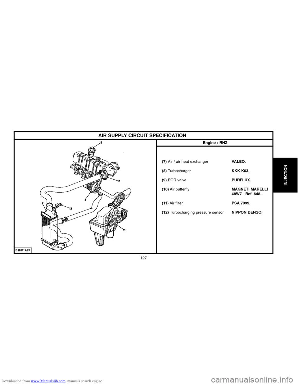
(7) Air / air heat exchanger VALEO.
(8) Turbocharger KKK K03.
(9)EGR valvePURFLUX.
(10)Air butterflyMAGNETI MARELLI
48W7 Ref. 648.
(11)Air filter PSA 7899.
(12) Turbocharging pressure sensorNIPPON DENSO.
AIR SUPPLY CIRCUIT SPECIFICATION
Engine : RHZ
B1HP1A7P
Page 140 of 259
![Citroen C5 2000 (DC/DE) / 1.G User Guide Downloaded from www.Manualslib.com manuals search engine CHECKS : TURBO PRESSURE
Engine : 4HX
TOOL
[1]Pressure gauge for checking pressure7073-T.A.
[2] Extension cable for taking pressure8607-T.A
[3]U Citroen C5 2000 (DC/DE) / 1.G User Guide Downloaded from www.Manualslib.com manuals search engine CHECKS : TURBO PRESSURE
Engine : 4HX
TOOL
[1]Pressure gauge for checking pressure7073-T.A.
[2] Extension cable for taking pressure8607-T.A
[3]U](/img/9/4134/w960_4134-139.png)
Downloaded from www.Manualslib.com manuals search engine CHECKS : TURBO PRESSURE
Engine : 4HX
TOOL
[1]Pressure gauge for checking pressure7073-T.A.
[2] Extension cable for taking pressure8607-T.A
[3]Union and hose for taking pressure8607-T.B.
[4] Adaptor for taking pressure8607-T.C.
[5]Unions and hoses for taking pressure4088-T
Checks.
ESSENTIAL : Respect the safety and cleanliness requirements specific to
high pressure diesel injection (HDi) engines.
Preliminary operations.
Carry out the following operations:
Remove the screw (1).
Disconnect the tube (2).
Move aside the pressure sensor (3).
Preparation of tools : in position on the vehicle.
Fit as follows :
Remove the hose(a)of tool [5], screw in its place the tool [3], remove the hose (b)of tool [5],
screw the hose (b)of tool [5]on the pressure gauge[1], screw the adaptor [4]onto the tool [5]
Connect the tube(2) of the pressure sensor(3) on the tool [4], tighten the tube(2) with a
Serflex type collar.
B1BP28DCE5AP1SUC
137
INJECTION
Page 141 of 259

Downloaded from www.Manualslib.com manuals search engine 138
INJECTION
B1BP28ECC5FPOBLC
CHECKS : TURBO PRESSURE
Engine : 4HX
Preparation of tools : in position on the vehicle (continued).
Screw the tool [3] on the take-off of the turbo air radiator at «c».
Place the pressure gauge on the cup holder at «d».
Connect the extension [2]on the hose «b»and tool [5].
ESSENTIAL : Observe the following checking requirements.
- Start the engine.
- Engage first gear and start the vehicle.
- Engage the gears up to third gear.
- Decelerate to1500 rpm.
Accelerate gradually : the pressures should be the following :
1,1 ± 0,05 b at 2000 rpm
1,2 ± 0,05 b at 3000 rpm.
Return the vehicle to normal.
Remove the tools [1],[2], [3], [4]and [5].
Reposition the pressure sensor (3).
Couple the tube(2).
Refit and tighten the screw (1).
Page 142 of 259

Downloaded from www.Manualslib.com manuals search engine FEATURES OF MULTIPOINT INJECTION SYSTEM
Summary
(1) Air pump
(2) Power steering pressure sensor
(3) Engine management ECU
(4) Canister purge electrovalve
(5)Butterfly housing
(6)Idle regulation stepper motor
(7) Inlet air temperature sensor
(8)Inlet housing heater element
(9)Butterfly potentiometer
(10)Automatic gearbox (Option)
(11)Built-in systems interface
(12) Transponder
(13)Diagnostic connector
(14) Ignition injection test warning lamp
(15)Battery
(16)Immobiliser unit
(17) Air conditioning
(18) Instrument panel
(19)Fuel tank
(20)Fuel pump, gauge and filter assembly(21)Canister reservoir
(22) Downstream oxygen sensor
(23)Upstream oxygen sensor
(24)Air inlet valve
(25)EGR electrovalve
(26)Camshaft position sensor
(27) Ignition coil
(28)Sparking plug
(29) Injector supply rail
(30)Injectors
(31) Air inlet pressure sensor
(32) Engine coolant temperature sensor
(33) Engine speed sensor
(34)Cooling fan unit
(35) Knock sensor
B1HP1C5P
139
INJECTION
Page 143 of 259

Downloaded from www.Manualslib.com manuals search engine 140
INJECTION
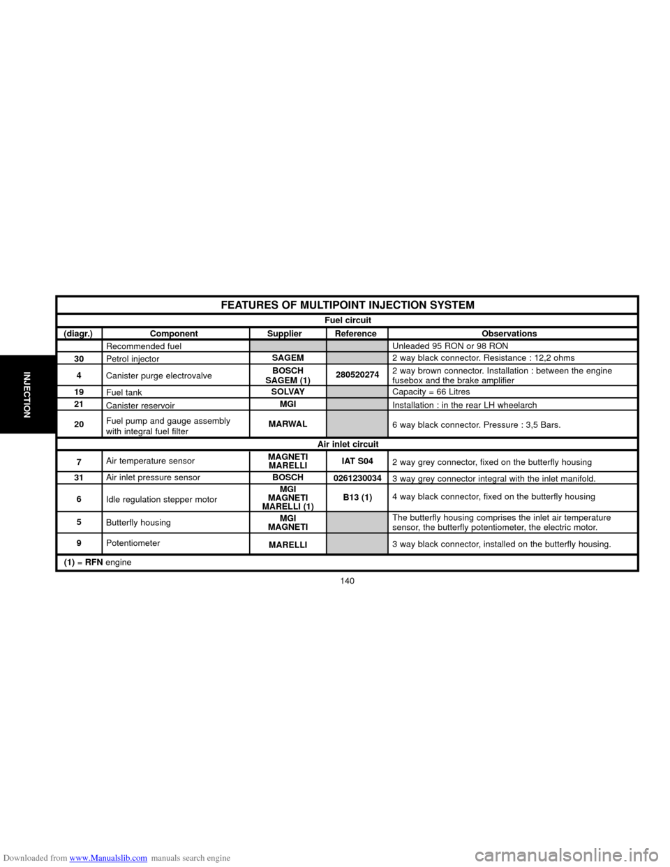
FEATURES OF MULTIPOINT INJECTION SYSTEM
Fuel circuit
Air inlet circuit
(diagr.) Component Supplier Reference Observations
30
4
19
21
20
7
31
6
5
9Recommended fuel
Petrol injector
Canister purge electrovalve
Fuel tank
Canister reservoir
Fuel pump and gauge assembly
with integral fuel filter
Air temperature sensor
Air inlet pressure sensor
Idle regulation stepper motor
Butterfly housing
PotentiometerSAGEM
BOSCH
SAGEM (1)
SOLVAY
MGI
MARWAL
MAGNETI
MARELLI
BOSCH
MGI
MAGNETI
MARELLI (1)
MGI
MAGNETI
MARELLI280520274
IAT S04
0261230034
B13 (1)Unleaded 95 RON or 98 RON
2 way black connector. Resistance : 12,2 ohms
2 way brown connector. Installation : between the engine
fusebox and the brake amplifier
Capacity = 66 Litres
Installation : in the rear LH wheelarch
6 way black connector. Pressure : 3,5 Bars.
2 way grey connector, fixed on the butterfly housing
3 way grey connector integral with the inlet manifold.
4 way black connector, fixed on the butterfly housing
The butterfly housing comprises the inlet air temperature
sensor, the butterfly potentiometer, the electric motor.
3 way black connector, installed on the butterfly housing.
(1) = RFNengine
Page 144 of 259

Downloaded from www.Manualslib.com manuals search engine 141
INJECTION
FEATURES OF MULTIPOINT INJECTION SYSTEM
Electrical circuit
(diagr.) Component Supplier Reference Observations
3
26
35
32
33
2
28
27Engine management ECU
with «FRIC»
Camshaft position sensor
Knock sensor
Engine coolant temperature sensor
Engine speed sensor
Power steering pressure sensor
Sparking plug
Ignition coilSAGEM
MAGNETI
MARELLIS2000
MM 48.P2
(1)
144323
F 207 326
257 603 2A
14 43 32
402 244 03
14 43 27
280 291
RFN52HZ
FR8ME
BBC2.2NDE
2 526 118 ELECTRIFIL
SIEMENS
SAGEM (1)
ELECTRIFIL
DAV
ELECTRIFIL
BITRON
(1)= EngineRFN
Ignition circuit
SAGEM
BOSCH
SAGEM
«Flash» eprom (reprogrammable eprom), sequential injection,
112 way connector.
3 way grey connector, fixed on the cylinder head
2 way black connector, fixed on the front part of the engine
block, tightening torque 2 ± 0.5 m.daN.
2 way green connector, fixed on the coolant outlet housing,
tightening torque 1.8 ± 0.1 m.daN.
2 way black connector, fixed on the clutch casing.
2 way blue connector, fixed on the power steering high pressure
pump outlet tube, tightening torque 2 ± 0.2 m.daN.
Electrode gap = 1mm.
Tightening torque 2.5 ± 0.2 m.daN.
4 way black connector.
Page 145 of 259

Downloaded from www.Manualslib.com manuals search engine 142
INJECTION
FEATURES OF MULTIPOINT INJECTION SYSTEM
Exhaust system
(diagr.) Component Supplier Reference Observations
23
22
1
2EGR electrovalve
Upstream oxygen sensor
Downstream oxygen sensor
Air pump
Air inlet valveDELPHI
NGK
BOSCH (1)
NGK
BOSCH (1)
SAGEM
SAGEM97097 A
OZA 495-PG2
OZA 341-PG7
2 590 004
2 580 0345 way black connector, installed on the cylinder head.
4 way blue connector, length of wire : 555 mm,
Tighten to 4.5 ± 0.4 m.daN.
6 way black connector, length of wire : 1500 mm,
Tighten to 4.5 ± 0.4 m.daN.
2 way black connector, located under the battery.
Installed on the cylinder head.
(1) = EngineRFN
Page 146 of 259

Downloaded from www.Manualslib.com manuals search engine FEATURES OF MULTIPOINT INJECTION SYSTEM
Summary
1)Accelerator pedal position sensor
(2)Denox catalyser downstream oxygen sensor
(3)Denox catalyser
(4)Downstream exhaust gas temperature sensor
(5)3-function precatalyser
(6)Precatalyser upstream oxygen sensor
(7) Upstream exhaust gas temperature sensor
(8)Petrol pressure regulator
(9)Petrol high pressure pump
(10)Knock sensor
(11) EGR electrovalve
(12)Canister purge electrovalve
(13)Motorised butterfly housing
(14)Canister reservoir
(15)Fuel pump and tank assembly
(16) Fuel tank
(17)Inlet air temperature sensor
(18) Inlet air pressure sensor(19)Engine coolant temperature sensor
(20) Sparking plug
(21) Ignition coil block
(22) High pressure injector
(23) Engine oil temperature sensor
(24)Engine speed sensor
(25)Inlet camshaft dephaser electrovalve
(26) Camshaft position sensor
(27)Petrol high pressure sensor
(28) Power steering pressure sensor
(29) Aircon fluid pressure sensor
(30)Cooling fan unit
(31)ABS block
(32)Clutch pedal sensor
(33)Brake pedal sensor
(34)Air conditioning ECU
(35) Engine management ECU
(36)Built-in systems interface BSI
(37)Rev counter
(38) Coded immobiliser
(39)Vehicle cruise control
(40) Diagnostic connector
B1HP1C6P
143
INJECTION
Page 147 of 259

Downloaded from www.Manualslib.com manuals search engine 144
INJECTION
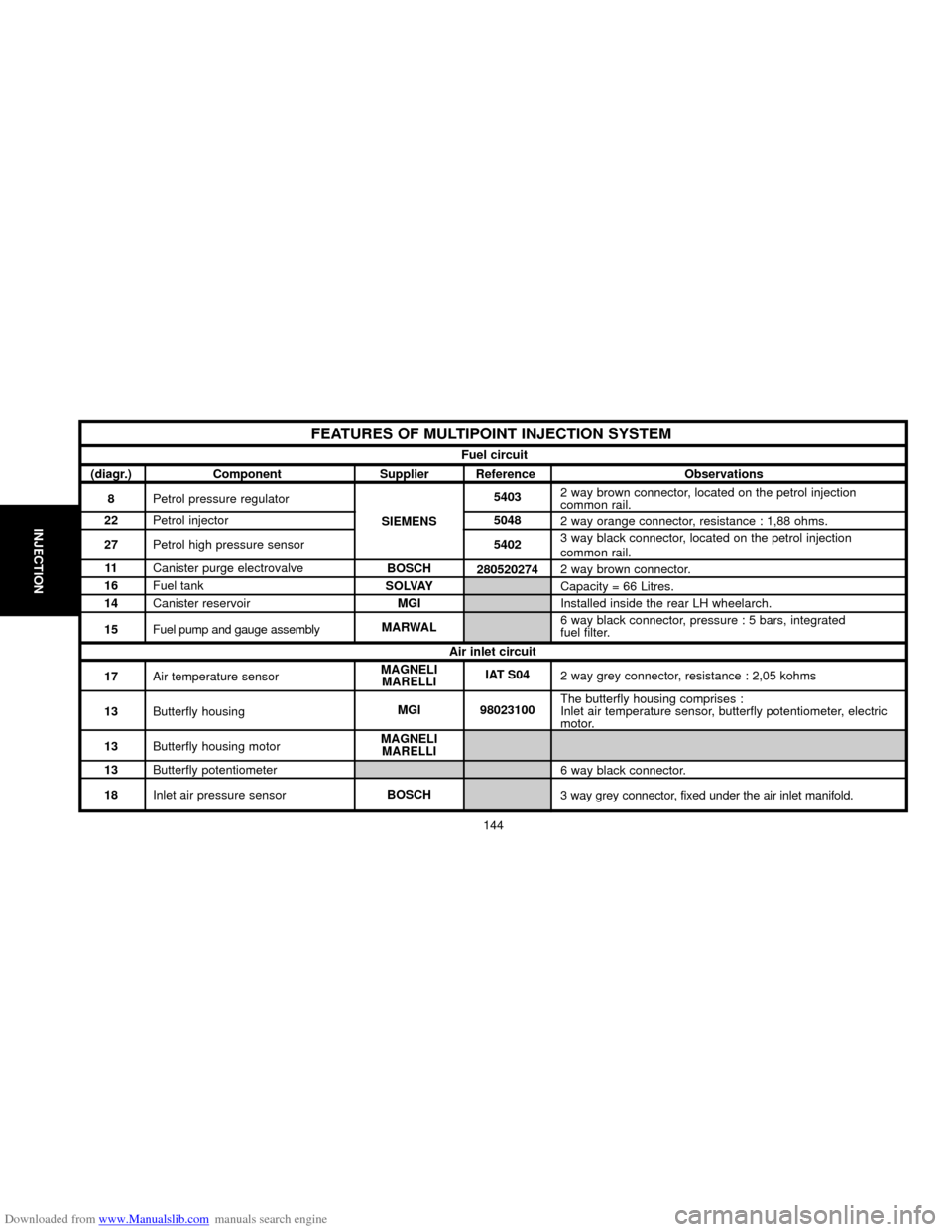
FEATURES OF MULTIPOINT INJECTION SYSTEM
Fuel circuit
(diagr.) Component Supplier Reference Observations
8Petrol pressure regulator
22Petrol injector
27Petrol high pressure sensor
11Canister purge electrovalve
16Fuel tank
14Canister reservoir
15Fuel pump and gauge assembly
17Air temperature sensor
13Butterfly housing
13Butterfly housing motor
13Butterfly potentiometer
18Inlet air pressure sensor2 way brown connector, located on the petrol injection
common rail.
2 way orange connector, resistance : 1,88 ohms.
3 way black connector, located on the petrol injection
common rail.
2 way brown connector.
Capacity = 66 Litres.
Installed inside the rear LH wheelarch.
6 way black connector, pressure : 5 bars, integrated
fuel filter.
2 way grey connector, resistance : 2,05 kohms
The butterfly housing comprises :
Inlet air temperature sensor, butterfly potentiometer, electric
motor.
6 way black connector.
3 way grey connector, fixed under the air inlet manifold. SIEMENS5403
5048
5402
280520274
IAT S04
98023100 BOSCH
SOLVAY
MGI
MARWAL
MAGNELI
MARELLI
MGI
MAGNELI
MARELLI
BOSCHAir inlet circuit